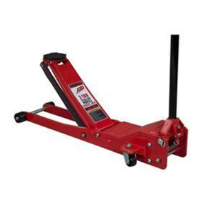
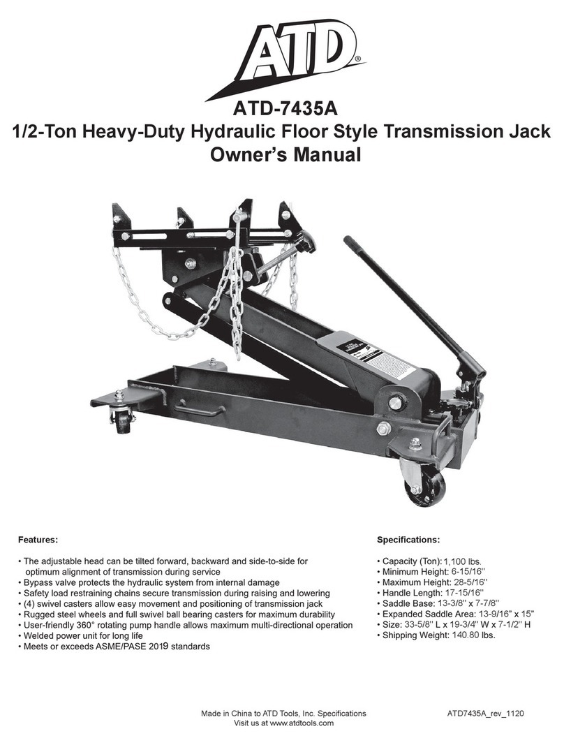
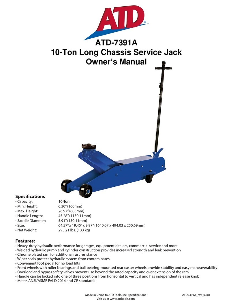
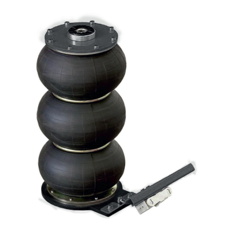
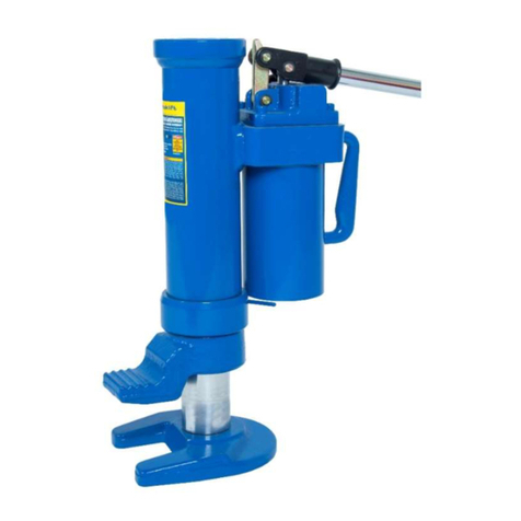
ATD Tools ATD-7433A User manual
Other ATD Tools Jack manuals
ATD Tools
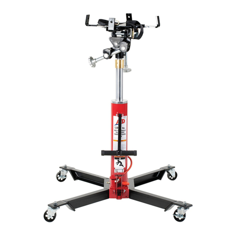
ATD Tools Atd-7430 Instructions for use
ATD Tools
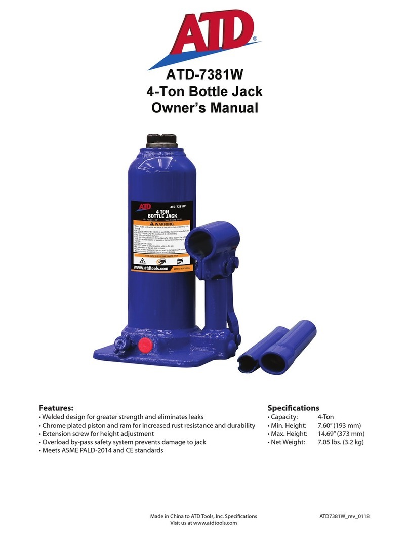
ATD Tools ATD-7381W User manual
ATD Tools
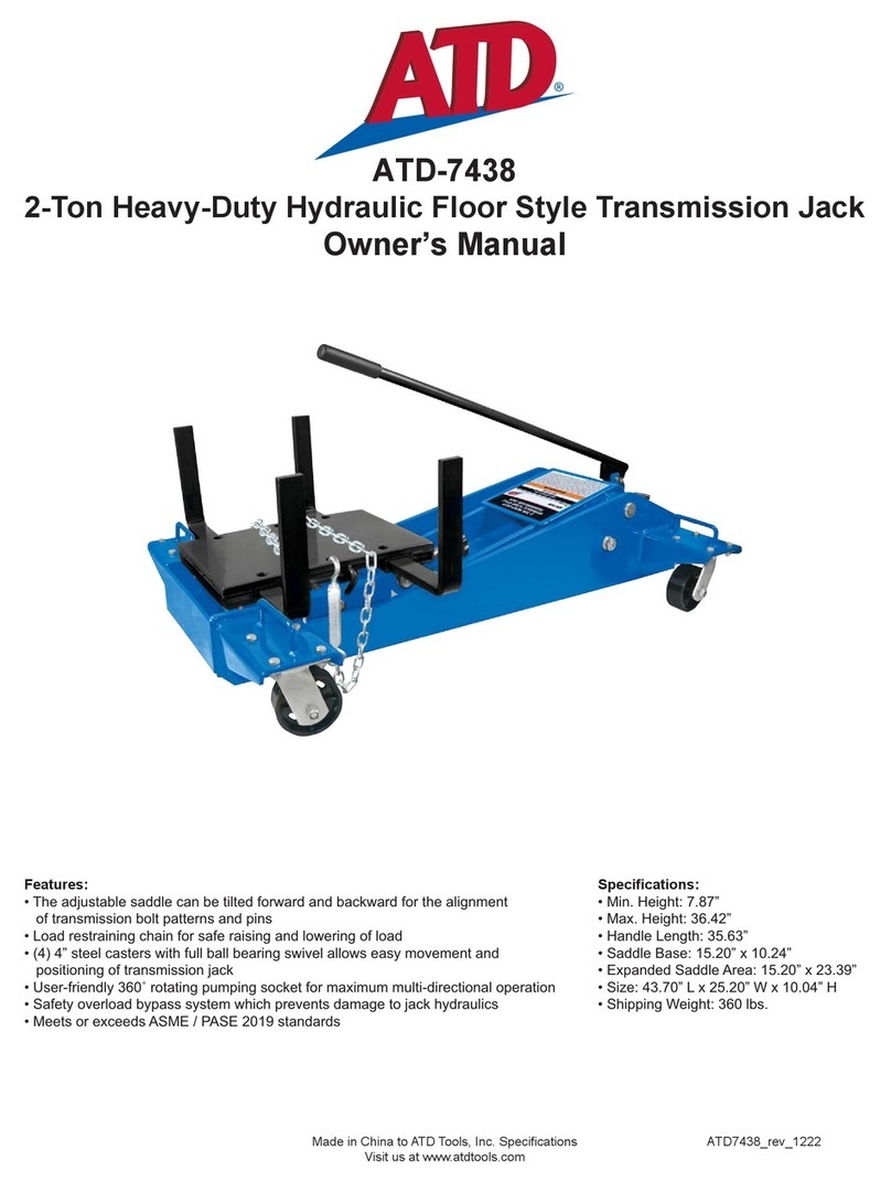
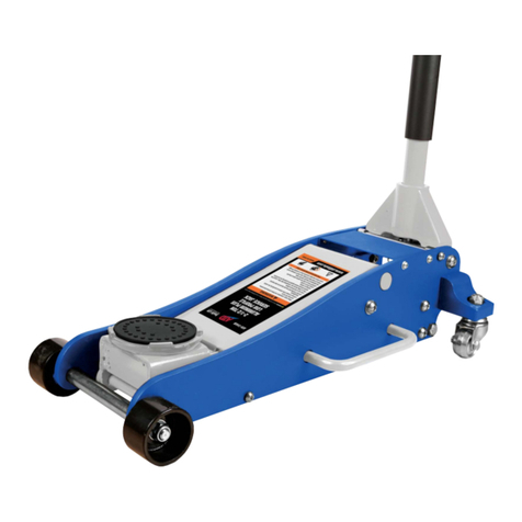
ATD Tools ATD-7438 User manual
ATD Tools
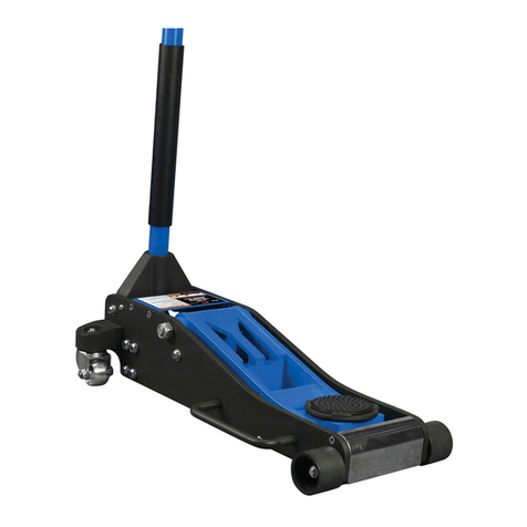
ATD Tools 7345B User manual
ATD Tools
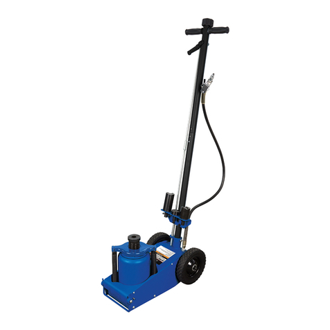
ATD Tools ATD-7343A User manual
ATD Tools
ATD Tools ATD-7328 User manual

ATD Tools
ATD Tools ATD-7304A User manual
ATD Tools
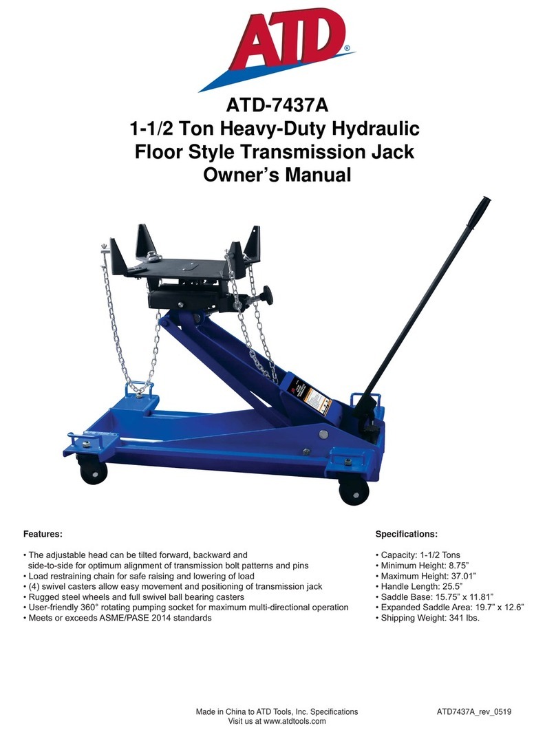
ATD Tools ATD-7437A User manual
ATD Tools
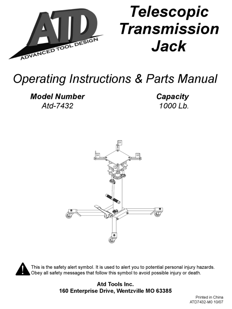
ATD Tools Atd-7432 Instructions for use
ATD Tools
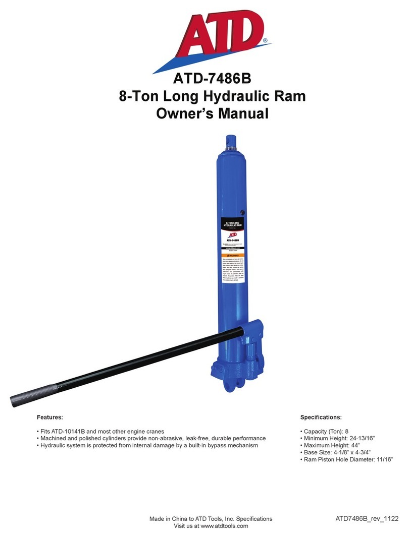
ATD Tools ATD-7486B User manual
ATD Tools
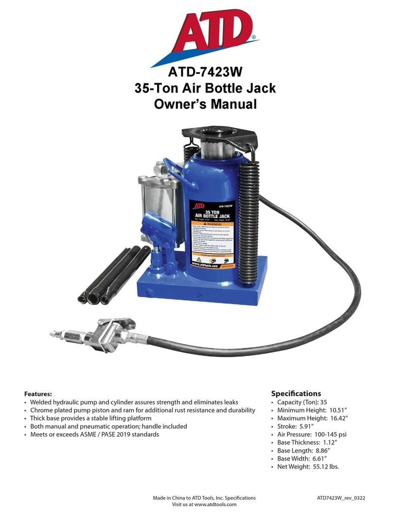
ATD Tools ATD-7423W User manual
ATD Tools
ATD Tools ATD-7344B User manual
ATD Tools
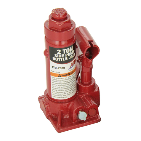
ATD Tools 7380 Instructions for use
ATD Tools
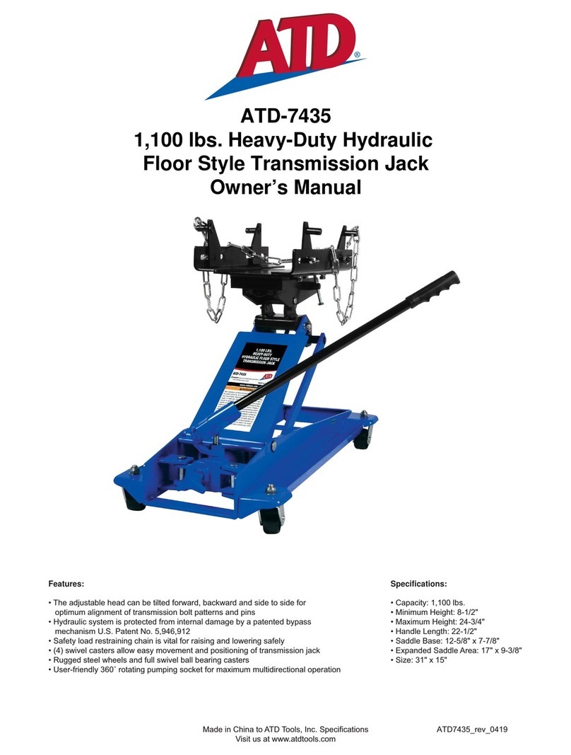
ATD Tools 7435 User manual
ATD Tools
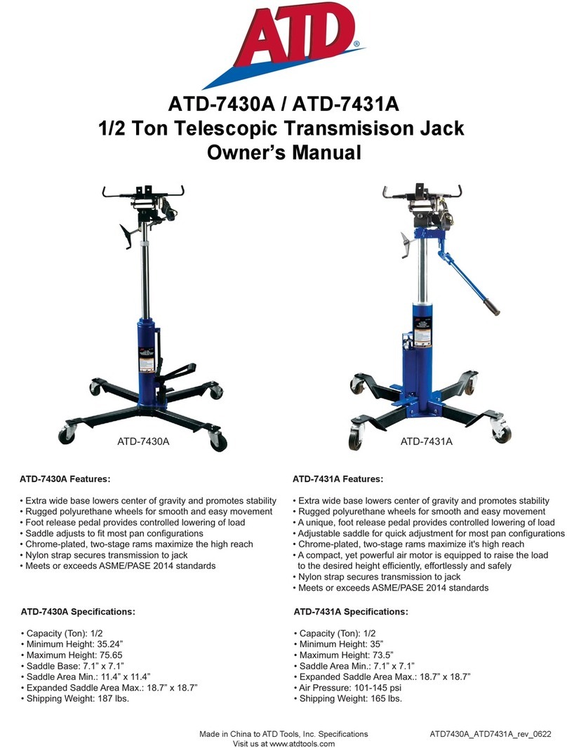
ATD Tools 7430A User manual
ATD Tools
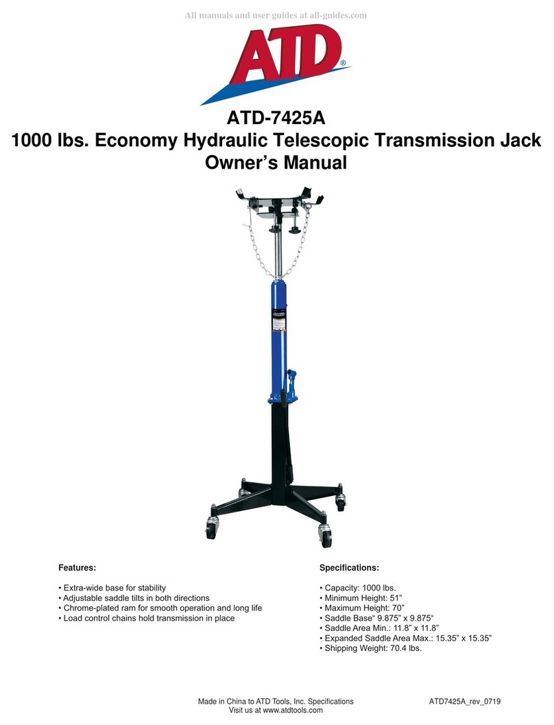
ATD Tools 7425A User manual
ATD Tools
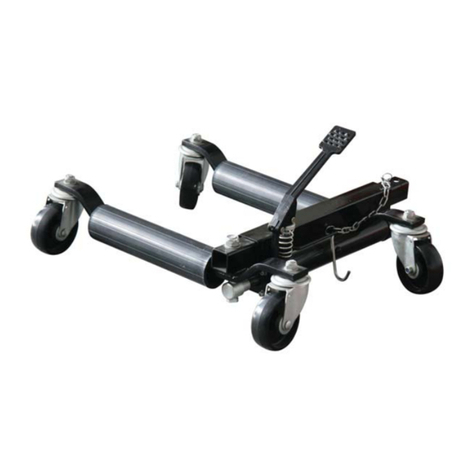
ATD Tools ATD-7465 User manual
ATD Tools
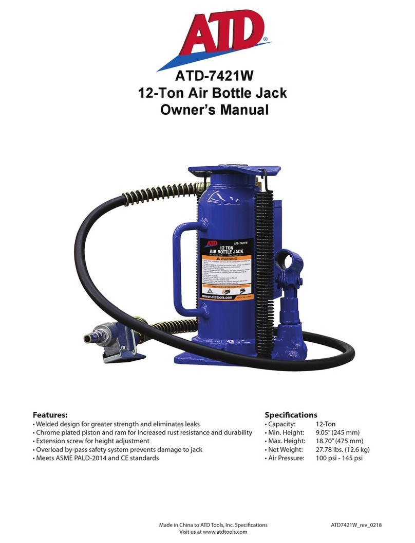
ATD Tools ATD-7421W User manual

ATD Tools
ATD Tools 7434A User manual
ATD Tools
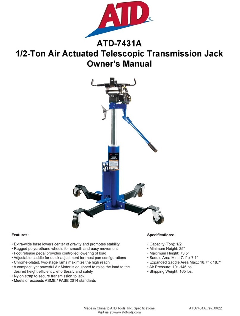
ATD Tools ATD-7431A User manual
Popular Jack manuals by other brands
Jegs
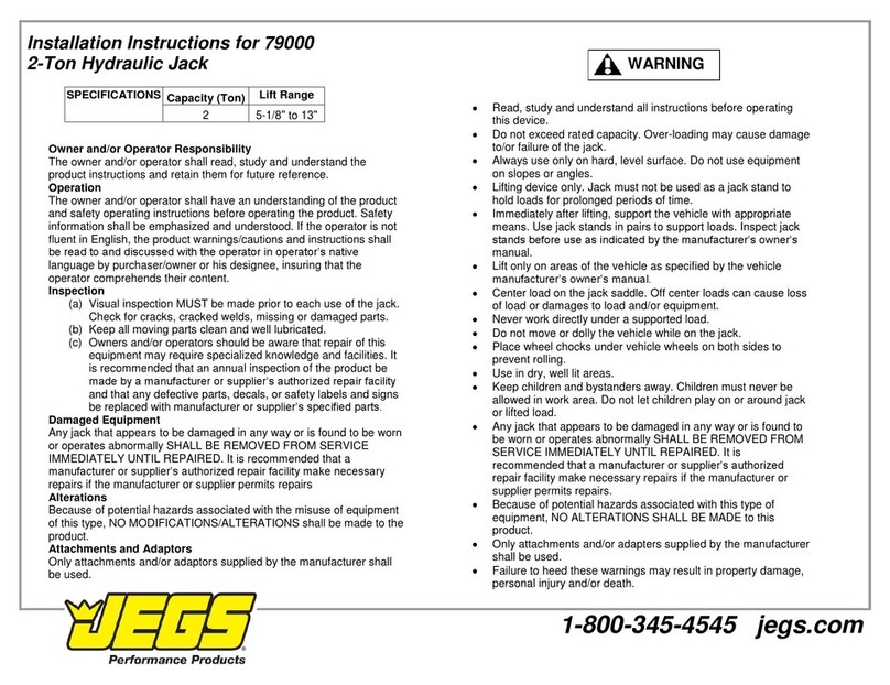
Jegs 79000 installation instructions
Esco
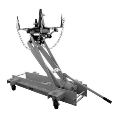
Esco YELLOW JACKIT 10812 operation instruction

Omega Lift Equipment
Omega Lift Equipment 23301C Operating instructions & parts manual
KNOVA
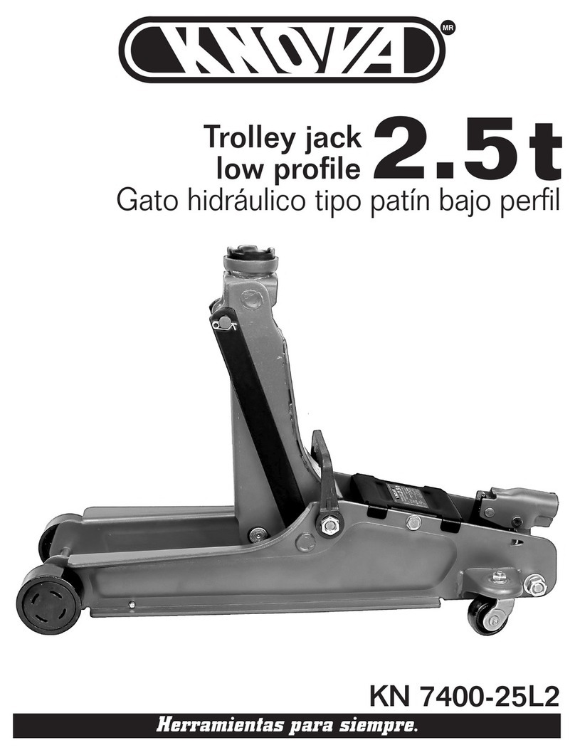
KNOVA KN 7400-25L2 manual

Pro-Lift
Pro-Lift PL1002 operating instructions
Cattini Oleopneumatica
Cattini Oleopneumatica YAK 1810X Operating and maintenance manual
Cattini Oleopneumatica
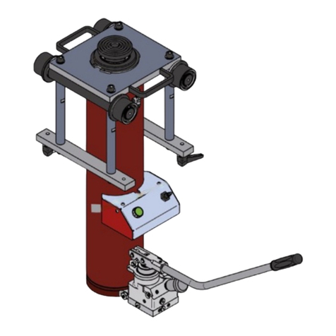
Cattini Oleopneumatica YAK 1820CX Operating and maintenance manual
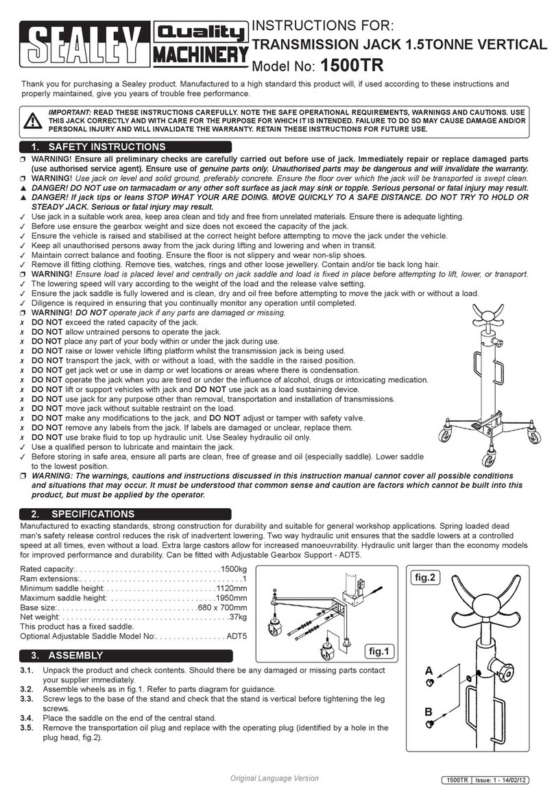
Sealey
Sealey Quality Machinery 1500TR instructions

Norco
Norco 72212 Setup, operating, maintenance instructions
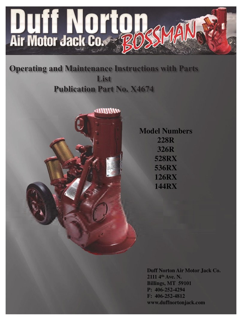
Duff-Norton
Duff-Norton 228-R Operating and Maintenance Instructions with Parts
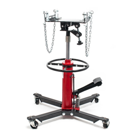
WilTec
WilTec 62420 Operation manual
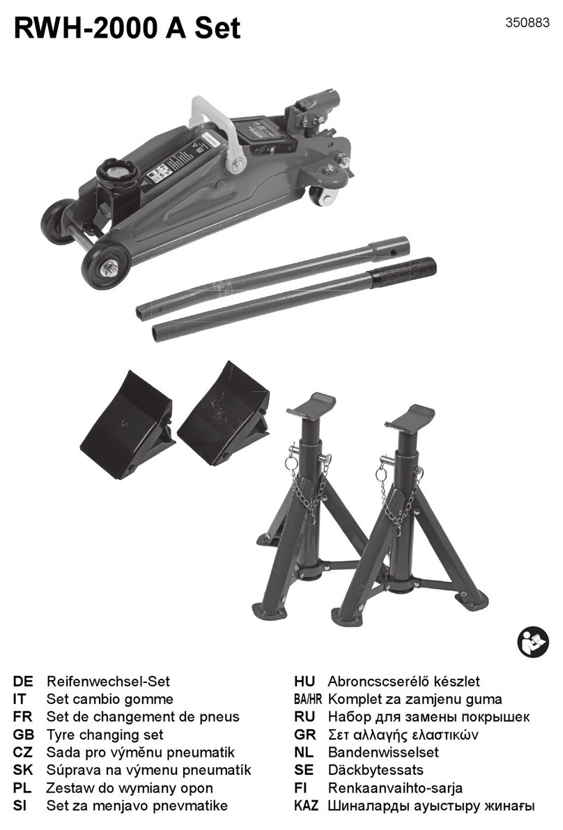
Emil Lux
Emil Lux RWH-2000 A manual


