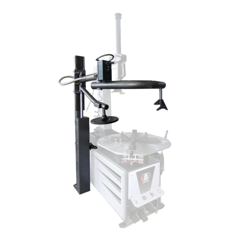
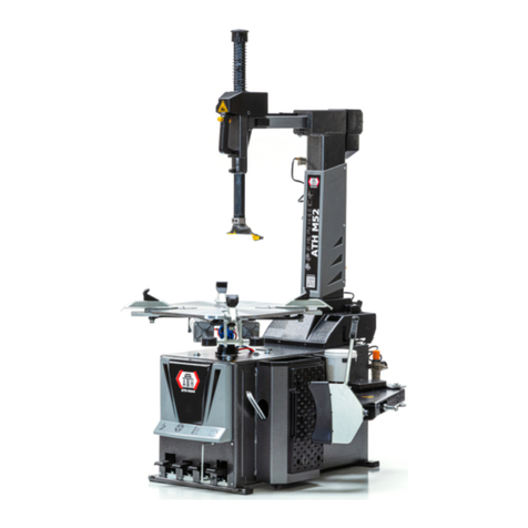
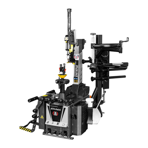
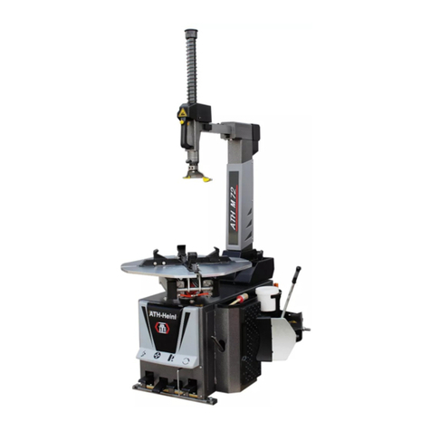
ATH-Heinl ATH M72Z User manual

OPERATING INSTRUCTIONS
ATH M72Z

® Copyright ATH-Heinl GmbH & Co. KG, 2019, All rights reserved / Misprints and technical changes reserved / As of: 2019-03
Manufacturer ATH-Heinl GmbH & CO.KG
- 2 -
Contents
1.0 INTRODUCTION ................................................................................................................... - 3 -
1.1 General Information ........................................................................................................... - 3 -
1.2 Description ........................................................................................................................ - 4 -
1.3 Operation.......................................................................................................................... - 7 -
1.4 Technical Data ................................................................................................................ - 19 -
1.5 Scale Drawing ................................................................................................................. - 20 -
2.0 INSTALLATION ................................................................................................................... - 21 -
2.1 Transport & Storage Conditions ........................................................................................ - 21 -
2.2 Unpacking the machine .................................................................................................... - 21 -
2.3 Delivery Contents ............................................................................................................ - 22 -
2.4 Location .......................................................................................................................... - 23 -
2.5 Fixing ............................................................................................................................. - 24 -
2.6 Electrical Connection ........................................................................................................ - 24 -
2.7 Pneumatic Connection ...................................................................................................... - 24 -
2.8 Hydraulic Connection ....................................................................................................... - 25 -
2.9 Assembly ........................................................................................................................ - 25 -
2.10 Completion of Work ...................................................................................................... - 26 -
3.0 OPERATION ....................................................................................................................... - 27 -
3.1 Operating Instructions ..................................................................................................... - 27 -
3.2 Basic Information ............................................................................................................ - 28 -
4.0 MAINTENANCE ................................................................................................................... - 29 -
4.1 Consumables for installation, maintenance and servicing..................................................... - 29 -
4.2 Safety Regulations for Oil ................................................................................................. - 30 -
4.3 Notes ............................................................................................................................. - 31 -
4.4 Maintenance or Service Plan ............................................................................................. - 31 -
4.5 Troubleshooting / Error Display and Solutions .................................................................... - 32 -
4.6 Maintenance and Service Instructions ................................................................................ - 33 -
4.7 Disposal .......................................................................................................................... - 36 -
5.0 EG-/EU-KONFORMITÄTSERKLÄRUNG / EC-/EU-DECLARATION OF CONFORMITY...................... - 37 -
6.0 APPENDIX .......................................................................................................................... - 38 -
6.1 Pneumatic circuit diagram ................................................................................................ - 38 -
6.2 Electric circuit diagram ..................................................................................................... - 39 -
6.3 Hydraulic circuit diagram .................................................................................................. - 40 -
7.0 WARRANTY CARD ............................................................................................................... - 41 -
7.1 Scope of the Product Warranty ......................................................................................... - 42 -
8.0 INSPECTION LOG ............................................................................................................... - 43 -
8.1 Installation and Handover Log .......................................................................................... - 44 -
8.2 Inspection Plan ................................................................................................................ - 45 -
8.3 Visual inspection (authorised expert) ................................................................................. - 46 -
9.0 SPARE PART BOOK ............................................................................................................. - 50 -
10.0 NOTES ............................................................................................................................... - 81 -
® Copyright ATH-Heinl GmbH & Co. KG, 2019, All rights reserved / Misprints and technical changes reserved / As of: 2019-03
Manufacturer ATH-Heinl GmbH & CO.KG
- 3 -
1.0 INTRODUCTION
1.1 General Information
THESE INSTRUCTIONS ARE AN INTEGRAL PART OF THE MACHINE.
THEY MUST BE READ AND UNDERSTOOD BY THE USER.
NO LIABILITY IS ASSUMED FOR ANY DAMAGES CAUSED BY FAILURE TO
FOLLOW THESE INSTRUCTIONS OR THE VALID SECURITY PROVISIONS.
WARNING: Follow the instructions to prevent injury or damage.
TIP: Provides more information on functionality and tips for using the device efficiently.
Appropriate protective clothing must be worn for all work on the described system.

® Copyright ATH-Heinl GmbH & Co. KG, 2019, All rights reserved / Misprints and technical changes reserved / As of: 2019-03
Manufacturer ATH-Heinl GmbH & CO.KG
- 4 -
1.2 Description
1 Handle with air valve To lock/unlock the horizontal & vertical movement of the assembly
head
2
Hexagonal bar
For vertical adjustment of the assembly head
3 Square bar For horizontal adjustment of the assembly head
4 Assembly head For assembling/disassembling tyres
5 Assembly tower Can be swivelled backwards
6 Rotary plate For rotating the wheel
7
Expansion shaft
For clamping the wheel
8
Grease containers
To store
the tyre grease
9 Bead breaker To remove the tyre from the wheel rim
10
Housing
11
Foot pedal control
12
Tyre inflator
To inflate the tyre
13
Compressed air maintenance
unit
A1
Hold
-
down roller
To press down the upper tyre bead
A2
Bead
breaker roller
To press down the lower tyre bead
A3
Second hold-down roller To press down the tyre bead at a second position
A4
Bead pusher To press down the tyre bead at a third position
A5
Assist-arm control For lifting and lowering the assist-arms
1
9
8
6
5
4
3
2
7
13
12
11
10
A1
A2
A3
A4
A5

® Copyright ATH-Heinl GmbH & Co. KG, 2019, All rights reserved / Misprints and technical changes reserved / As of: 2019-03
Manufacturer ATH-Heinl GmbH & CO.KG
- 5 -
1
Press the pedal down so that the rotary plate moves clockwise.
2nd sentence deleted
Pull the pedal upwards to move the rotary plate anticlockwise.
2
Press the pedal to work with the bead breaker blade. When you
release it again, the bead breaker blade will return to the
starting position.
3
Press the pedal to swing the assembly tower backwards.
Press it again to swing the assembly tower forwards again.
1
2
3

® Copyright ATH-Heinl GmbH & Co. KG, 2019, All rights reserved / Misprints and technical changes reserved / As of: 2019-03
Manufacturer ATH-Heinl GmbH & CO.KG
- 6 -
When you press the button (1), both the hexagonal (2) and the
square (3) bars are held in the position that has been set.
These can be unlocked again by pulling the button and released
to adjust the assembly head (4).
Operating the assist
-
arm
A5.1 Control lever for the upwards and downwards movement of
the assembly roller and bead pusher.
3
2
1
4
A5.1

® Copyright ATH-Heinl GmbH & Co. KG, 2019, All rights reserved / Misprints and technical changes reserved / As of: 2019-03
Manufacturer ATH-Heinl GmbH & CO.KG
- 7 -
1.3 Operation
1.3.1 Determining the wheel rim cut
On some wheel rims, the nut in the middle of the wheel rim is
very flat or there is no nut.
This type of wheel rim is not authorised for sale in some
countries.
On some wheel rims, the nut in the middle of the wheel rim is
very deep, meaning that, for assembly or disassembly, the tyre
has to be pushed in very deep. This increases the risk of
damaging the tyre.
Some wheels have a tyre pressure control system. This system
may not be damaged on assembly or disassembly.

® Copyright ATH-Heinl GmbH & Co. KG, 2019, All rights reserved / Misprints and technical changes reserved / As of: 2019-03
Manufacturer ATH-Heinl GmbH & CO.KG
- 8 -
1.3.2 Tyre bead breaker
Preparation
Check the following points before using the device:
- Check oil level, water level and air pressure on the maintenance unit
- Check whether the power supply is connected properly.
Unscrew the valve insert on the wheel valve and let out all the air.
Turn and/or tension the clamping plate into a position which does
not allow any components (cylinder, pneumatic fittings, etc.) to be
touched by the tyre.
Turn the wheel rim so that you can first apply the bead breaker to
the outer side of the wheel rim.
Place the depressurised wheel to the side, on the special rubber
pad on the machine housing.
You can place the bead breaker blade on the outside of the tyre
using the control lever. In order to complete the assembly without
any damage, the blade must be positioned around 1 cm from the
edge of the rim flange.
Press the gear change pedal for the bead breaker until the tyre has
come off the wheel rim and then release the pedal IMMEDIATELY.
Continue to turn the wheel and repeat the bead breaking process
until the tyre has come away from the wheel rim all the way
round.
In order to make it easier to then disassemble the tyre and/or to
proceed more gently on the tyre and the wheel rim, it is advisable
to cover the parts of the tyre and wheel rim that are being
released with a standard assembly paste each time you insert the
bead breaker blade.
Only used approved products!
Repeat the procedure for the second wheel side.

® Copyright ATH-Heinl GmbH & Co. KG, 2019, All rights reserved / Misprints and technical changes reserved / As of: 2019-03
Manufacturer ATH-Heinl GmbH & CO.KG
- 9 -
1.3.3 Clamping the wheels
Preparation
Check the following points before you mount the wheel:
- Dirt and old balancing weights must be removed from the wheel
- Check the total weight of the wheel
The way in which the tyre will be lifted and handled is determined when the wheel is
placed on the clamping plate.
If the weight is less than 25 kg, lifting can be carried out by one person.
If the weight exceeds 25 kg, lifting must be carried out by two persons or by a wheel lift.
If the weight exceeds 50 kg, lifting must be carried out by a wheel lift.
- Select the appropriate configuration
Adap
ter for standard rims
Adapter for rims with a concave centre hole

® Copyright ATH-Heinl GmbH & Co. KG, 2019, All rights reserved / Misprints and technical changes reserved / As of: 2019-03
Manufacturer ATH-Heinl GmbH & CO.KG
- 10 -
For “reverse” rims
For light truck rims

® Copyright ATH-Heinl GmbH & Co. KG, 2019, All rights reserved / Misprints and technical changes reserved / As of: 2019-03
Manufacturer ATH-Heinl GmbH & CO.KG
- 11 -
For rims with no inner hole
For rims made from thin material

® Copyright ATH-Heinl GmbH & Co. KG, 2019, All rights reserved / Misprints and technical changes reserved / As of: 2019-03
Manufacturer ATH-Heinl GmbH & CO.KG
- 12 -
Clamping
Remove the locking device from the assembly head.
Move the assembly head into position as high and as far back as
possible and lock it again.
Now swivel the assembly tower backwards.
Wheel rims with asymmetric drop-centres should be positioned so
that the narrow bead seat is facing up.
In order to prevent damage to alloy wheels when clamping, it is
recommended to only clamp these using the cone and plastic
protectors.
Position the wheel rim on the clamping plate.
The mounting finger on the clamping plate must be
inserted into one of the rim holes.
Pick up the expansion shaft including the clamping nut, cone and, if
necessary, the spacer adapter.
Pull the upper handle and guide the complete clamping unit through
the centre hole on the rim and into the hexagon socket on the
rotary plate. Release the upper handle.
Guide the cone to the rim by actuating the quick-action lever.
Secure the wheel by turning the complete quick-action chuck with
the foldable handles.

® Copyright ATH-Heinl GmbH & Co. KG, 2019, All rights reserved / Misprints and technical changes reserved / As of: 2019-03
Manufacturer ATH-Heinl GmbH & CO.KG
- 13 -
1.3.4 Setting up the assembly head
If you are predominantly processing large wheels up to 24” or small 8” wheels, it is
advisable to adapt the assembly head settings to the wheel rim diameter.
The settings for the assembly head are set out in more detail in the MAINTENANCE
subsection.
Tip and/or swivel the assembly head into the working position
and release the locking device in order to bring the assembly
head up to the rim flange by hand and put it on. In order to do
so, the guide roller (3) and/or the plastic contact strip (for light
metal wheel rims) may touch the respective wheel rim contour.
When locking the assembly head, this automatically moves away
from the wheel rim in height and distance.
The settings for the automatic distance are set out in the
“Maintenance and service work” chapter.
In order to prevent light metal wheel rims from being damaged
during assembly, it is advisable to only assemble these using a
plastic protector and/or a plastic assembly head.

® Copyright ATH-Heinl GmbH & Co. KG, 2019, All rights reserved / Misprints and technical changes reserved / As of: 2019-03
Manufacturer ATH-Heinl GmbH & CO.KG
- 14 -
1.3.5 Disassembling a tyre
In principle, the guidelines of the German Rubber Industry Trade Association
(Wirtschaftsverband der deutschen Kautschukindustrie) should be observed when
disassembling tyres.
Turn and/or set the stretched wheel so that the wheel valve is
approx. 10 cm in front of the assembly head
Press the tyre bead down against the opposite side of the
assembly head.
Then lever the tyre over the assembly head using the assembly
iron. During levering, the tyre moves into the drop-centre of the
wheel rim and facilitates simple and damage-free assembly.
In order to make it easier to lift the bead and to protect the
wheel, position the bead pusher opposite the assembly head.
Press the bead in 3, 6 and 12 o’clock position up to the first
wheel rim depression, ensuring that the tyre is not compressed
whilst doing so.
Press down the gear change pedal for the rotational motion of
the clamping plate so the rotational motion starts clockwise.
Whilst doing so, continue to hold the assembly iron on the bar of
the assembly head by pressing the iron against the assembly
head.
As soon as approx. 1/3 of the tyre bead has passed the rim
flange, there should be enough room to remove the assembly
iron.
Continue with the rotational motion until the whole tyre is above
the rim flange.
When working with tubular tyres, the tube should now be
removed from the tyre.

® Copyright ATH-Heinl GmbH & Co. KG, 2019, All rights reserved / Misprints and technical changes reserved / As of: 2019-03
Manufacturer ATH-Heinl GmbH & CO.KG
- 15 -
In order to lever the lower tyre bead, lift the tyre until it is at the
same height as the drop-centre of the wheel rim.
Then, position the assembly iron between the tyre and the
assembly head and lift the tyre directly under the assembly head.
Now lever the tyre bead over the wheel rim and commence the
rotational motion in the same way as for the upper bead.
After disassembly, press down on the gear change pedal to move
the assembly tower so it swivels back.
Then remove the tyre.
1.3.6 Assembling a tyre
In principle, the guidelines of the German Rubber Industry Trade Association
(Wirtschaftsverband der deutschen Kautschukindustrie) should be observed when
assembling tyres.
The tyre valve should be changed before assembly.
Clamp and/or set the wheel rim so that the wheel valve is
approximately 180 degrees over the assembly head.
Cover the tyre and the wheel rim in a sufficient amount of assembly
paste.

® Copyright ATH-Heinl GmbH & Co. KG, 2019, All rights reserved / Misprints and technical changes reserved / As of: 2019-03
Manufacturer ATH-Heinl GmbH & CO.KG
- 16 -
Check whether the assembly head is in the correct position for the
wheel rim. If necessary, set it up as described in the subsection
“Setting up the assembly head”.
Now place the tyre on the wheel rim at an angle so that the
assembly head does not touch any parts of the tyre when
swivelling.
Swivel the assembly tower by pressing the corresponding pedal.
Position the tyre so that the tyre bead is under the nose, but still on
the guideway of the assembly head.
When doing so, ensure that the tyre is opposite the assembly head
in the wheel rim depression.
Start the rotational movement of the clamping plate.
During the assembly process, ensure that the bead run is correct.
Failing to ensure this can cause serious damage to the tyre.
When working with tubular tyres, the tube must be positioned
correctly in the tyre. Ensure that it is positioned in the tyre such that
it will not be damaged during the remainder of the assembly
process.

® Copyright ATH-Heinl GmbH & Co. KG, 2019, All rights reserved / Misprints and technical changes reserved / As of: 2019-03
Manufacturer ATH-Heinl GmbH & CO.KG
- 17 -
When assembling the second bead, follow the exact same
procedure as for the first bead.
You must also ensure that the tyre is positioned correctly in relation
to the assembly head.
Start the rotational movement of the clamping plate.
During the assembly process, ensure that the bead run is correct.
Failing to ensure this can cause serious damage to the tyre.
In order to complete the process, release the wheel rim clamp to
remove the wheel.

® Copyright ATH-Heinl GmbH & Co. KG, 2019, All rights reserved / Misprints and technical changes reserved / As of: 2019-03
Manufacturer ATH-Heinl GmbH & CO.KG
- 18 -
1.3.7 Inflating tyres
The maximum tyre pressure may not exceed 3.5 bar.
All parts of the body should be kept away from the tyre.
During operation the noise level can reach 85 dB (A), so the operator should take
appropriate protective measures.
Ensure that the tyre has been fully lubricated.
Start the inflation process.
If the air volume of the tyre inflator is not sufficient to push the tyre
over the wheel rim, you can increase the air volume by removing the
inner valve. This must be replaced quickly afterwards.
Ensure that the tyre has been inflated to the correct pressure.
Consult the manufacturer’s specifications to establish this.
If the tyre pressure is too low, this can lead to increased wear and
decrease the service life of the tyre. The inside of the tyre can also
be damaged.
The tyre pressure must be checked once a week.
Only check the tyre pressure at normal tyre temperatures (i.e. the
vehicle has not been driven for more than an hour and not more
than 2-3 km)

® Copyright ATH-Heinl GmbH & Co. KG, 2019, All rights reserved / Misprints and technical changes reserved / As of: 2019-03
Manufacturer ATH-Heinl GmbH & CO.KG
- 19 -
1.4 Technical Data
Max. rim centre hole diameter (z) 45 - 130 mm
Rim diameter (B) 12 - 27 inches
Max. rim width (A)
approx. 4
-
13 inches
[depending on offset (ET)]
Max. entry diameter (B + tyre) 1050 mm
Max. working range of bead breaker 83 - 350 mm
Max. force of bead breaker 2500 kg
Rotary plate torque
1100 Nm
Rotary plate speed
6 / 12 rpm
Power supply 380 / 50 – 16 V/Hz - A
(220 / 50 – 16 V/Hz - A)
Drive power
0.75 kW
Motor
speed
1400 / 2800 rpm
Working pressure 8 - 10 bar
(0.8 - 1.0 Mpa)
Noise emission < 70 dB
Net weight
345 kg
Gross weight 390 kg
Definition of wheel rim
A = wheel rim width (without “f” flange)
B = wheel rim diameter (without “f” flange)
f = flange
h = hump
t = drop-centre
z = centre ring
ET = offset
1 = rim centre
2 = contact surface
1 inch = 2.54 centimetres

® Copyright ATH-Heinl GmbH & Co. KG, 2019, All rights reserved / Misprints and technical changes reserved / As of: 2019-03
Manufacturer ATH-Heinl GmbH & CO.KG
- 20 -
1.5 Scale Drawing
1120
-
1740 mm
1770
-
2170 mm
1050
-
1550 mm
Table of contents
Other ATH-Heinl Tyre Changer manuals

ATH-Heinl
ATH-Heinl 7226 User manual

ATH-Heinl
ATH-Heinl M72 User manual

ATH-Heinl
ATH-Heinl M126 User manual

ATH-Heinl
ATH-Heinl A31 User manual

ATH-Heinl
ATH-Heinl ATH M32 User manual

ATH-Heinl
ATH-Heinl M72 User manual

ATH-Heinl
ATH-Heinl M156 User manual

ATH-Heinl
ATH-Heinl M72Z Plus User manual

ATH-Heinl
ATH-Heinl M32 User manual
Popular Tyre Changer manuals by other brands

HENNESSY INDUSTRIES
HENNESSY INDUSTRIES Coats Rim Clamp RC150EX operating instructions

Cormach
Cormach CM SUPER 27 Use and maintenance manual

M&B Engineering
M&B Engineering TC 325 Original instructions

Cormach
Cormach SUPER VIGOR 2450 Use and maintenance manual

Ravaglioli
Ravaglioli RAV GTB-16N E-Z Operation

John Bean
John Bean QUADRIGA 1000 Operator's manual