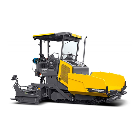
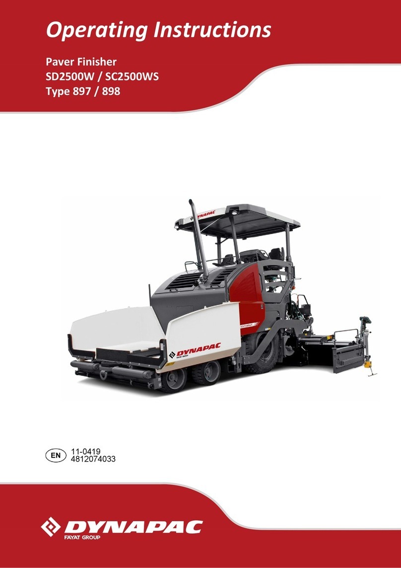
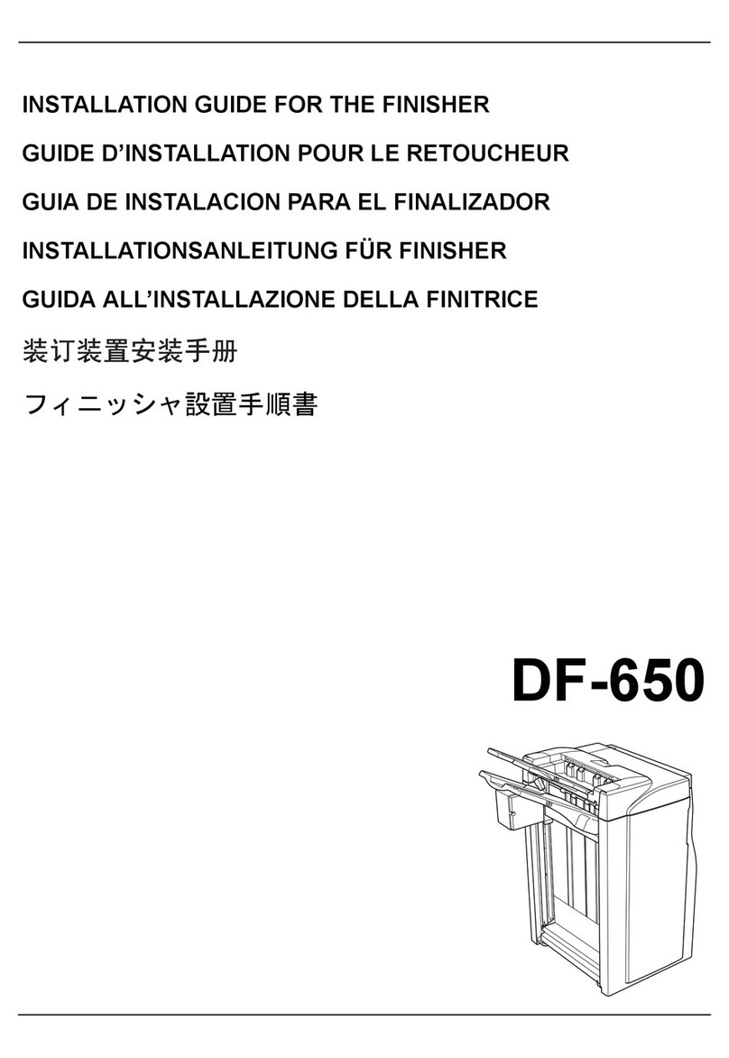
Atlas Copco SD2550C User manual

OPERATION & MAINTENANCE
Paver Finisher
Dynapac
SD2550C / SD2550CS
Typ 894 / 895
Keep for later use in document compartment
4812008809 (A5)
03-0513
Valid for:
_________________ - _________________
_________________ - _________________

www.atlascopco.com

1
Table of contents
V Preface ..................................................................................... 1
1 General safety instructions ........................................................................ 2
1.1 Laws, guidelines, accident prevention regulations ..................................... 2
1.2 Safety signs, signal words ......................................................................... 3
"Danger"! ............................................................................................... 3
"Warning" ! ............................................................................................. 3
"Caution" ! .............................................................................................. 3
"Note" ! ................................................................................................... 3
1.3 Other supplementary information ............................................................... 3
1.4 Warnings .................................................................................................... 4
1.5 Prohibitive symbols .................................................................................... 6
1.6 Protective equipment ................................................................................. 7
1.7 Environmental protection ........................................................................... 8
1.8 Fire prevention ........................................................................................... 8
1.9 Additional information ................................................................................ 9
2 CE identification and Declaration of Conformity ...................................... 10
3 Guarantee conditions ............................................................................... 10
4 Residual risks ........................................................................................... 11
5 Sensibly predictable incorrect usage ....................................................... 12
A Correct use and application ................................................... 1
B Vehicle description ................................................................. 1
1 Application ................................................................................................. 1
2 Description of assemblies and functions .................................................... 2
2.1 Vehicle ....................................................................................................... 3
Construction ........................................................................................... 3
3 Danger zones ............................................................................................. 7
4 Safety devices ............................................................................................ 8
5 Technical data, standard configuration .................................................... 10
5.1 Dimensions (all dimensions in mm) ......................................................... 10
5.2 Allowed angle of rise and slope ............................................................... 11
5.3 Permissible approach angle ..................................................................... 11
5.4 Weights SD2550C (all weights in t) ......................................................... 12
5.5 Weights SD2550CS (all weights in t) ....................................................... 12
5.6 Performance data SD2550C .................................................................... 13
5.7 Performance data SD2550CS ................................................................. 14
5.8 Travel drive/traction unit ........................................................................... 15
5.9 Engine SD2550C ..................................................................................... 15
5.10 Engine SD2550C >/= s/n GG001804 ....................................................... 15
5.11 Engine SD2550CS ................................................................................... 15
5.12 Hydraulic system ...................................................................................... 16
5.13 Material compartment (hopper) ................................................................ 17
5.14 Material transfer ....................................................................................... 17
5.15 Material distribution SD2550C ................................................................. 17

2
5.16 Material distribution SD2550CS ...............................................................17
5.17 Screed lifting device .................................................................................18
5.18 Electrical system ......................................................................................18
5.19 Permissible temperature ranges ..............................................................18
6 Location of instruction labels and identification plates .............................19
6.1 Warning signs ...........................................................................................22
6.2 Information signs ......................................................................................25
6.3 CE marking ...............................................................................................27
6.4 Instructive symbols, prohibitive symbols, warning symbols .....................28
6.5 Danger symbols .......................................................................................29
6.6 Further warnings and operating instructions ............................................30
6.7 Identification label for the paver finisher (41) ........................................32
7 EN standards ............................................................................................33
7.1 Continuous sound pressure SD2550C, Cummins QSB 6.7-C260 ...........33
7.2 Operating conditions during measurement ..............................................33
7.3 Measuring point configuration ..................................................................33
7.4 Continuous sound pressure SD2550CS, Cummins QSB 6.7-C260 .........34
7.5 Operating conditions during measurement ..............................................34
7.6 Measuring point configuration ..................................................................34
7.7 Vibration acting on the entire body ...........................................................35
7.8 Vibrations acting on hands and arms .......................................................35
7.9 Electromagnetic compatibility (EMC) .......................................................35
C11 Transportation .........................................................................1
1 Safety regulations for transportation ..........................................................1
2 Transportation on low-bed trailers ..............................................................2
2.1 Preparations ...............................................................................................2
3 Securing the load .......................................................................................4
3.1 Prepare the low-bed trailer .........................................................................4
3.2 Driving onto the low-bed trailer ...................................................................5
3.3 Lashing equipment .....................................................................................6
3.4 Loading .......................................................................................................7
3.5 Preparing the machine ...............................................................................8
4 Securing the load .......................................................................................9
4.1 Securing at the sides ..................................................................................9
4.2 Securing at the front ...................................................................................9
4.3 Securing at the rear - screed with side board ...........................................10
4.4 Securing at the rear - screed without side board ......................................11
Step 1: fasten lashing straps ................................................................11
Step 2: fasten lashing chains ...............................................................11
5 Control panel transport safeguard: ..........................................................12
5.1 After transportation ...................................................................................13
Protective roof (o) .................................................................................14
6 Transportation ..........................................................................................16
6.1 Preparations .............................................................................................16
6.2 Driving mode ............................................................................................18
7 Loading by crane ......................................................................................19
8 Towing ......................................................................................................22
9 Safely parking the vehicle ........................................................................24

3
9.1 Lifting the vehicle with hydraulic lifts, lifting points ................................... 25
D11 Operation ................................................................................. 1
1 Safety regulations ...................................................................................... 1
2 Controls ...................................................................................................... 3
2.1 Operating panel ......................................................................................... 3
2.2 Special functions ...................................................................................... 50
Reversible conveyor ............................................................................ 50
3 Remote control ......................................................................................... 53
D21 Operation ................................................................................. 1
1 Operation of the input and display terminal ............................................... 1
Button layout on the display ................................................................... 1
Command symbols ................................................................................ 2
1.1 Menu operation .......................................................................................... 3
Main menu ............................................................................................ 5
Displays: ................................................................................................ 5
Active / inactive display function .......................................................... 9
"Engine speed" menu .......................................................................... 10
Set-up menu Engine speed ................................................................. 10
Measured value display Drive engine .................................................. 11
"Paving parameters" menu .................................................................. 12
Set-up menu Paving parameters ......................................................... 12
Paving parameters Save ..................................................................... 13
Paving parameters Load ...................................................................... 13
Actual value display Auger, conveyor, tamper, vibration(o) ................ 14
Set-up menu Screed heater ................................................................. 14
Menu Paving area / automatic steering unit ........................................ 15
Menu "Machine settings memory" ....................................................... 16
Set-up menu - "Delayed screed start" ................................................. 16
Menu "Camera display" ....................................................................... 17
"Camera 2" display .............................................................................. 17
Menu "Front wheel drive" (o) ............................................................... 18
Menu - "Error memory" ........................................................................ 19
Display "Machine error messages" ...................................................... 19
Display "Engine error messages" ........................................................ 20
Menu "System information &basic settings" ........................................ 21
Menu "Service" .................................................................................... 22
Set-up menu "Levelling" ...................................................................... 23
Set-up menu "Screed type" ................................................................. 23
Set-up menu "Terminal settings" ........................................................ 24
System menu - "Basic settings" display ............................................... 24
2 Terminal error messages ......................................................................... 25
2.1 Drive engine error codes .......................................................................... 26
2.2 Error codes .............................................................................................. 28
3 Menu structure of the setting and display menus .................................... 35

4
D30 Operation .................................................................................1
1 Operating elements on the paver finisher ..................................................1
1.1 Control elements on the operator's control station .....................................1
Protective roof (o) ...................................................................................2
Ladder ....................................................................................................4
Storage space ........................................................................................4
Control platform, moveable (o) ...............................................................5
Control platform lock (o) .........................................................................6
Operating panel ......................................................................................7
Protective cabin (o) ................................................................................8
Windscreen wiper ...................................................................................9
.Emergency actuation control platform, movable .................................10
Seat console ........................................................................................11
Driver's seat, type I .............................................................................12
Driver's seat, type II ............................................................................13
Fuse box ..............................................................................................14
Batteries ...............................................................................................15
Main battery switch ..............................................................................15
Hopper transport safeguard .................................................................16
Screed lock, mechanical (o) .................................................................16
Screed lock, hydraulic (o) .....................................................................17
Paving thickness indicator ...................................................................18
Auger lighting (o) ..................................................................................19
Engine compartment lighting (o) ..........................................................19
LED working light (o) ............................................................................20
500 watt spotlight (o) ............................................................................21
Camera (o) ...........................................................................................21
Auger height adjustment ratchet (o) .....................................................22
Auger height indicators .......................................................................22
Sensor rod / sensor rod extension ......................................................23
Manual separator fluid spray (o) ..........................................................25
Separator fluid spraying system (o) .....................................................26
Conveyor limit switches - PLC version .................................................27
Conveyor limit switches - conventional version ....................................28
Ultrasonic auger limit switches (left and right) - PLC version ...............29
Ultrasonic auger limit switches (left and right) - conventional version ..30
24 volt / 12 volt sockets (o) ..................................................................31
Pressure control valve for screed charging/relieving ...........................32
Pressure control valve for paving stop with relieving ...........................32
Manometer for screed charging/relieving .............................................32
Central lubrication system (o) ..............................................................33
Lane clearer (o) ....................................................................................34
Screed eccentric adjustment ................................................................35
Push roller crossbar, adjustable ...........................................................36
Push roller crossbar, hydraulically extendable (o) ...............................37
Push roller damping, hydraulic (o) .......................................................37
Fire extinguisher (o) .............................................................................38
First-aid kit (o) ......................................................................................38
Rotary beacon (o) ................................................................................39

5
Fuelling pump (o) ................................................................................. 40
Illuminated balloon (o) ......................................................................... 41
Installation and operation ..................................................................... 42
Maintenance ........................................................................................ 43
Replacing the lamp .............................................................................. 43
D41 Operation ................................................................................. 1
1 Preparing for operation .............................................................................. 1
Required devices and aids .................................................................... 1
Before starting work (in the morning or when starting paving) .............. 3
Check list for the vehicle operator ......................................................... 3
1.1 Starting the paver finisher .......................................................................... 6
Before starting the paver finisher ........................................................... 6
"Normal" starting .................................................................................... 6
External starting (starting aid) ................................................................ 8
After starting ........................................................................................ 11
Observe indicator lamps ...................................................................... 13
Engine coolant temperature check (79) ............................................... 13
Battery charge indicator (83) ............................................................... 13
Oil pressure indicator lamp for the diesel engine (86) ......................... 13
Oil pressure indicator lamp for the travel drive (87) ............................. 15
1.2 Preparation for transportation .................................................................. 17
Driving and stopping the paver finisher ............................................... 19
1.3 Preparations for paving ............................................................................ 20
Separator fluid ..................................................................................... 20
Screed heater system .......................................................................... 20
Direction marks .................................................................................... 21
Loading/conveying material ................................................................. 23
1.4 Starting for paving .................................................................................... 25
1.5 Checks during paving .............................................................................. 26
Paver function ...................................................................................... 26
Quality of the layer ............................................................................... 26
1.6 Paving with "screed control at paving stop" and "screed
charging/relieving" .................................................................................... 27
General ................................................................................................ 27
Screed charging/relieving .................................................................... 29
Screed control with paver finisher stop / in paving operation
(screed stop / paving stop / floating paving) ........................................ 29
Adjusting the pressure ......................................................................... 33
Setting pressure for screed control with paving stop + relieving: ........ 33
1.7 Interrupting/terminating operation ............................................................ 35
During breaks (e.g. the material supply truck is late) ........................... 35
During longer breaks(e.g. lunch break) ............................................... 35
When work is finished .......................................................................... 37
2 Malfunctions ............................................................................................. 38
2.1 Problems during paving ........................................................................... 38
2.2 Malfunctions on the paver finisher or screed ........................................... 40

6
E11 Set-up and modification .........................................................1
1 Special notes on safety ..............................................................................1
2 Distribution auger .......................................................................................2
2.1 Height adjustment ......................................................................................2
Grain sizes up to 16 mm ........................................................................2
Grain sizes > 16 mm ..............................................................................2
2.2 Mechanical adjustment with ratchet (o) ......................................................3
2.3 Hydraulic adjustment (o) ............................................................................3
2.4 Height adjustment for large working widths / with brace ............................4
3 Auger extension .........................................................................................6
3.1 Mounting extension parts ...........................................................................7
Mounting the material shaft and auger extension ..................................7
Mounting the outer auger bearing ..........................................................8
Mounting the auger end bearing ............................................................9
3.2 Auger extension chart ..............................................................................10
Auger upgrading, working width 3.14 m ...............................................12
Auger upgrading, working width 3.78 m ...............................................12
Auger upgrading, working width 4.42 m ...............................................12
Auger upgrading, working width 5.06 m ...............................................13
Auger upgrading, working width 5.70 m ...............................................13
Auger upgrading, working width 6.34 m ...............................................14
Auger upgrading, working width 6.98 m ...............................................15
Auger upgrading, working width 7.62 m ...............................................16
Auger upgrading, working width 8.26 m ...............................................17
Auger upgrading, working width 8.90 m ...............................................18
Auger upgrading, working width 9.54 m ...............................................19
Auger upgrading, working width 10.18 m .............................................20
Auger upgrading, working width 10.82 m .............................................21
Auger upgrading, working width 11.46 m .............................................22
Auger upgrading, working width 12.10 m .............................................23
Auger upgrading, working width 12.74 m .............................................24
3.3 Mounting the auger brace ........................................................................25
3.4 Aligning the auger ....................................................................................27
3.5 Material shaft, hinged ...............................................................................29
3.6 Hopper scraper .........................................................................................30
3.7 Crossbeam guide .....................................................................................31
4 Offsetting the screed ................................................................................32
5 Levelling ...................................................................................................33
5.1 Slope controller ........................................................................................33
5.2 Mounting the sensor arm ..........................................................................34
5.3 Mounting the grade control system ..........................................................34
5.4 Setting up the sensor arm ........................................................................35
5.5 Big ski 9 m, big ski 13 m ..........................................................................36
Mounting the big ski bracket on the crossbeam ...................................38
Mounting the swivel arms .....................................................................39
Mounting the centre element ................................................................40
Extending the big ski ............................................................................41
Mounting the sensor bracket ................................................................42
Mounting and aligning the sensors ......................................................43
7
Mounting the distributor box ................................................................ 44
Connection diagram ............................................................................. 45
5.6 Levelling shoe 6m, 9m ............................................................................ 46
6 Automatic steering unit ............................................................................ 48
6.1 Mounting the automatic steering unit on the paver finisher ..................... 49
Mounting and aligning the sensor ........................................................ 50
Connecting the sensor ......................................................................... 50
Automatic steering unit operating instructions ..................................... 51
7 Emergency stop during feeder operation ................................................. 52
8 Limit switch .............................................................................................. 53
8.1 Auger limit switches (left and right) - mounting the PLC version ............. 53
9 Special accessories ................................................................................. 54
9.1 Material bucket ......................................................................................... 54
Application ........................................................................................... 54
Description of assemblies and functions ............................................. 55
Technical data ..................................................................................... 56
Dimensions, bucket MH2500 - (short version) ..................................... 56
Dimensions, bucket MH2550 - (long version) ...................................... 57
Weights ............................................................................................... 58
Volume ................................................................................................. 58
10 Identification points .................................................................................. 59
10.1 Information signs ...................................................................................... 60
10.2 Warning signs .......................................................................................... 60
10.3 Further warnings and operating instructions ............................................ 60
10.4 Instructive symbols, prohibitive symbols, warning symbols ..................... 61
Load securing - bucket ........................................................................ 62
Prepare the low loader ......................................................................... 62
Lashing equipment .............................................................................. 63
Lashing ................................................................................................ 64
Loading with the crane - MH2500 ........................................................ 66
Loading with the crane - MH2550 ........................................................ 67
Lash the bucket in the paver ................................................................ 69
Operation ............................................................................................. 71
Operation with a feeder with slewing belt ............................................ 72
Preparations for paving ........................................................................ 72
Separator fluid ..................................................................................... 72
Cleaning the bucket ............................................................................. 73
11 Screed ...................................................................................................... 74
12 Electrical connections .............................................................................. 74
12.1 Machine operation without remote control / side board ........................... 75
F10 Maintenance ............................................................................ 1
1 Notes regarding safety ............................................................................... 1
F22 Maintenance review ................................................................ 1
1 Maintenance review ................................................................................... 1

8
F31 Maintenance - conveyor .........................................................1
1 Maintenance - conveyor .............................................................................1
1.1 Maintenance intervals ................................................................................3
1.2 Points of maintenance ................................................................................4
Chain tension, conveyor (1) ...................................................................4
Conveyor drive - drive chains (2) ...........................................................6
Conveyor deflectors / conveyor plates (3) ..............................................7
F40 Maintenance - auger assembly .............................................. 1
1 Maintenance - auger assembly ..................................................................1
1.1 Maintenance intervals ................................................................................3
1.2 Points of maintenance ................................................................................5
Outer auger bearing (1) ..........................................................................5
Auger planetary gear (2) ........................................................................6
Drive chains of the augers (3) ................................................................7
Auger box (4) .........................................................................................8
Seals and sealing rings (5) .....................................................................9
Gearbox bolts Check tightening (6) ......................................................10
Mounting screws - Outer auger bearing Check tightening (7) ..............11
Auger blade (8) ....................................................................................12
F50 Maintenance - engine assembly Tier 3 (o) ............................ 1
1 Maintenance - engine assembly .................................................................1
1.1 Maintenance intervals ................................................................................3
1.2 Points of maintenance ................................................................................6
Engine fuel tank (1) ...............................................................................6
Engine lube oil system (2) .....................................................................7
Engine fuel system (3) ........................................................................10
Engine air filter (4) ................................................................................12
Engine cooling system (5) ....................................................................14
Engine drive belt (6) .............................................................................16
F60 Maintenance - hydraulic system ............................................1
1 Maintenance - hydraulic system .................................................................1
1.1 Maintenance intervals ................................................................................3
1.2 Points of maintenance ................................................................................5
Hydraulic oil tank (1) ..............................................................................5
Suction/return flow hydraulic filter (2) .....................................................7
Bleeding the filter ...................................................................................8
Ventilation filter .......................................................................................8
High-pressure filter (3) ...........................................................................9
Pump distribution gear (4) ....................................................................10
Bleeder ................................................................................................11
Hydraulic hoses (5) ..............................................................................12
Marking hydraulic hoses / storage period, period of use ......................14
Auxiliary flow filter (6) ...........................................................................15

9
F74 Maintenance – drive units ...................................................... 1
1 Maintenance – drive units .......................................................................... 1
1.1 Maintenance intervals ................................................................................ 3
1.2 Points of maintenance ............................................................................... 6
Chain tension (1) ................................................................................... 6
Bottom plates (2) ................................................................................... 9
Rollers (3) ............................................................................................ 10
Planetary gear (4) ................................................................................ 11
Screw connections ............................................................................... 13
F81 Maintenance - electrical system ............................................ 1
1 Maintenance - electrical system ................................................................. 1
1.1 Maintenance intervals ................................................................................ 3
1.2 Points of maintenance ............................................................................... 4
Batteries (1) ........................................................................................... 4
Recharging the batteries ........................................................................ 5
Alternator (2) .......................................................................................... 6
Insulation faults ...................................................................................... 7
Cleaning the generator .......................................................................... 8
Electrical fuses / relays (3) ..................................................................... 9
Fuses in terminal box (B) .................................................................... 10
Relays in terminal box (C) .................................................................. 12
Relays in the engine compartment (E) ................................................ 14
F90 Maintenance - lubricating points ........................................... 1
1 Maintenance - lubricating points ................................................................ 1
1.1 Maintenance intervals ................................................................................ 2
1.2 Points of maintenance ............................................................................... 3
Central lubrication system (1) ................................................................ 3
Bearing points (2) .................................................................................. 7
F100 Tests, stopping ....................................................................... 1
1 Tests, checks, cleaning, stopping .............................................................. 1
1.1 Maintenance intervals ................................................................................ 2
2 General visual inspection ........................................................................... 3
3 Check that the bolts and nuts fit firmly ....................................................... 3
4 Inspection by an expert .............................................................................. 4
5 Cleaning ..................................................................................................... 5
5.1 Cleaning the hopper ................................................................................... 6
5.2 Cleaning the conveyor and auger .............................................................. 6
6 Preserving the paver finisher ..................................................................... 7
6.1 Shutdowns for up to 6 months ................................................................... 7
6.2 Shutdowns lasting from 6 months to 1 year ............................................... 7
6.3 Recommissioning the machine .................................................................. 7
7 Environmental protection, disposal ............................................................ 8
7.1 Environmental protection ........................................................................... 8

10
7.2 Disposal ......................................................................................................8
8 Bolts - torques ............................................................................................9
8.1 Standard metric threads - strength class 8.8 / 10.9 / 12.9 ..........................9
8.2 Fine metric threads - strength class 8.8 / 10.9 / 12.9 ...............................10
F110 Lubricants and operating substances .................................. 1
1 Lubricants and operating substances .........................................................1
1.1 Capacities ...................................................................................................3
2 Lubricant specifications ..............................................................................4
2.1 Engine ........................................................................................................4
2.2 Cooling system ...........................................................................................4
2.3 Hydraulic system ........................................................................................4
2.4 Pump distribution gear ...............................................................................4
2.5 Drive unit planetary gear ............................................................................5
2.6 Auger drive planetary gear .........................................................................5
2.7 Auger box ..................................................................................................5
2.8 Grease .......................................................................................................5
2.9 Hydraulic oil ................................................................................................6

V 1
VPreface
Translation of the original operating instructions.
If the vehicle is to be operated safely, the information provided in these operating in-
structions will be required. The information is provided in a concise, clearly structured
form. The individual chapters are arranged in alphabetical order. and every chapter
starts with page 1. The individual pages are identified by the chapter letter and the
page number.
Example: Page B 2 is the second page of chapter B.
These operating instructions cover various vehicle options. Make sure that during op-
eration and maintenance work the description appropriate to the vehicle option is
used.
In the interest of continued development, the manufacturer reserves the right to make
changes to the vehicle (which will not, however, change the essential features of the
type of vehicle described) without updating the present operating instructions at the
same time.
Dynapac GmbH
Wardenburg
Ammerländer Strasse 93
D-26203 Wardenburg / Germany
Telephone: +49 / (0)4407 / 972-0
Fax: +49 / (0)4407 / 972-228
www.dynapac.com

V 2
1 General safety instructions
1.1 Laws, guidelines, accident prevention regulations
AThe locally applicable laws, guidelines and accident prevention regulations must al-
ways be observed, even if these are not expressly named here.
The user himself/herself is responsible for compliance with the resulting regulations
and measures!
AThe following warnings, prohibitive symbols and instructive symbols indicate dangers
for persons, the vehicle and the environment due to residual risks when operating the
vehicle.
AFailure to observe this information, prohibitions and instructions can result in life-
threatening injuries!
AThe "Guidelines for the Correct Use and Application of Paver Finishers" compiled by
Dynapac must also be observed!

V 3
1.2 Safety signs, signal words
In the safety instructions, the signal words "Danger", "Warning", "Caution", "Note" are
positioned in the coloured title block. They follow a certain hierarchy; in combination
with the warning symbol, they indicate the severity of the danger or the type of note.
"Danger"!
Danger of personal injury.
Indication of an immediately threatening danger that result in fatal or severe injuries
unless the corresponding actions are taken.
"Warning" !
Indication of a possible danger that can result in fatal or se-
vere injuries unless the corresponding actions are taken.
"Caution" !
Indication of a possible danger that result in moderate or mi-
nor injuries unless the corresponding actions are taken.
"Note" !
Indication of a possible drawback unless the corresponding
actions are taken, e.g. unwanted conditions or consequences can occur.
1.3 Other supplementary information
Other information and important explanations are identified by the following picto-
grams:
fPrecedes safety instructions that must be observed in order to prevent danger to per-
sonnel.
mPrecedes notes that must be observed to prevent damage to equipment.
APrecedes general notes and explanations.
DANGER
WARNING
CAUTION
NOTE

V 4
1.4 Warnings
Warning on a dangerous area or hazard!
Failure to observe the warnings can result in life-threatening inju-
ries!
Warning on danger of being pulled in!
mIn this working area/on this element there is a danger of being pulled
in by rotating or conveying elements!
Only carry out activities with elements switched off!
Warning on dangerous electrical voltage!
mAll maintenance and repair work on the screed's electrical system
must always be carried out by an electrician!
Warning on suspended loads!
mNever stand under suspended loads!
Warning on danger of crushing!
mThere is a danger of crushing when certain components are operat-
ed, or certain functions or vehicle movements are carried out.
Always make sure that there are no persons within the endangered
areas!
Warning on hand injuries!
Warning on hot surfaces or hot liquids!

V 5
Warning on danger of falling!
Warning on dangers posed by batteries!
Warning on hazardous or irritating substances!
Warning on substances which constitute a fire hazard!
Warning on gas bottles!

V 6
1.5 Prohibitive symbols
Opening/walking on/reaching in/carrying out/setting up are prohibit-
ed during operation or while the drive engine is running!
Do not start engine/drive!
Maintenance and repair work may only be carried out with the diesel
engine shut down!
Spraying with water is prohibited!
Extinguishing with water is prohibited!
Unauthorised maintenance is prohibited!
Only qualified experts may conduct maintenance!
AConsult the Dynapac Service Department
Fire!, naked flames and smoking are prohibited!
Do not switch!

V 7
1.6 Protective equipment
ALocally applicable regulations may require the wearing of various safety equipment!
Always observe these regulations!
Wear safety goggles to protect your eyes!
Wear suitable head protection!
Wear suitable hearing protection to protect your hearing!
Wear suitable safety gloves to protect your hands!
Wear safety shoes to protect your feet!
Always wear close-fitting work clothing!
Wear a warning vest to be seen in time to avoid accidents!
Wear respiratory equipment if breathing air is contaminated!

V 8
1.7 Environmental protection
AThe locally applicable laws, guidelines and accident prevention regulations for the
proper recycling and disposal of waste must always be observed, even if these are
not expressly named here.
Water-endangering substances like:
- Lubricants (oil, grease)
- Hydraulic oil
-Dieselfuel
- Coolant
- Cleaning liquids
must not get into the soil or sewer system during cleaning, maintenance and repair
work!
Substances must be caught, stored, transported and brought to pro-
fessional disposal sites in suitable containers!
Environmentally hazardous substance!
1.8 Fire prevention
ALocally applicable regulations may require suitable extinguishing agents to be carried
on the vehicle!
Always observe these regulations!
Fire extinguisher!
(optional equipment)
Other manuals for SD2550C
1
This manual suits for next models
1
Table of contents
Other Atlas Copco Finisher manuals

Atlas Copco
Atlas Copco Dynapac SD2500WS Manual

Atlas Copco
Atlas Copco Dynapac F1000W T4i Troubleshooting guide

Atlas Copco
Atlas Copco Dynapac F1800W Troubleshooting guide

Atlas Copco
Atlas Copco Dynapac F1800C Troubleshooting guide

Atlas Copco
Atlas Copco DYNAPAC Svedala Demag DF 115 C Troubleshooting guide