Atlas Copco CLG 10 Maintenance and service guide

Safety and operating instructions
Lubricators
© 2015 Construction Tools PC AB | No. 9800 1172 01a | 2015-04-10
Original instructions
CLG 10, 10 US, 30, 30 US


Contents
Introduction........................................................................5
About the Safety and operating instructions..........................................5
Safety instructions.................................................................6
Safety signal words..............................................................6
Personal precautions and qualifications...........................................6
Personal protective equipment...................................................6
Drugs, alcohol or medication....................................................6
Installation, precautions..........................................................6
Operation, precautions...........................................................6
Maintenance, precautions........................................................7
Storage, precautions.............................................................7
Overview...........................................................................8
Design and function.............................................................8
Main parts.......................................................................8
Labels..........................................................................8
Safety label...................................................................9
Installation.........................................................................9
Hoses and connections..........................................................9
Lubrication......................................................................9
Oil adjustment.................................................................9
Operation..........................................................................9
Operating.......................................................................9
Fillingthelubricatorwithoil......................................................9
Maintenance......................................................................10
Every day......................................................................10
Periodic maintenance...........................................................10
Assembly instruction...........................................................10
Troubleshooting...................................................................10
Storage...........................................................................11
Disposal..........................................................................11
Technical data.....................................................................12
Machine data...................................................................12
3© 2015 Construction Tools PC AB | No. 9800 1172 01a | 2015-04-10
Original instructions
ContentsCLG 10, 10 US, 30, 30 US


Introduction
Thank you for choosing a product from Atlas Copco. Since 1873, we have been
committed to finding new and better ways of fulfilling our customers' needs.
Through the years, we have developed innovative and ergonomic product
designs that have helped customers improve and rationalize their daily work.
Atlas Copco has a strong global sales and service network, consisting of
customer centers and distributors worldwide. Our experts are highly trained
professionals with extensive product knowledge and application experience.
In all corners of the world, we can offer product support and expertise to ensure
that our customers can work at maximum efficiency at all times.
For more information please visit: www.atlascopco.com
Construction Tools PC AB
Box 703
391 27 Kalmar
Sweden
About the Safety and operating
instructions
The aim of the instructions is to provide you with knowledge of how to use the
machine in an efficient, safe way. The instructions also give you advice and
tell you how to perform regular maintenance on the machine.
Before using the machine for the first time you must read these instructions
carefully and understand all of them.
5© 2015 Construction Tools PC AB | No. 9800 1172 01a | 2015-04-10
Original instructions
Safety and operating instructionsCLG 10, 10 US, 30, 30 US

Safety instructions
To reduce the risk of serious injury or death to
yourself or others, read and understand the Safety
and operating instruction before installing, operating,
repairing, maintaining, or changing accessories on
the machine.
Post this Safety and operating instruction at work
locations, provide copies to employees, and make
sure that everyone reads the Safety and operating
instruction before operating or servicing the machine.
For professional use only.
In addition, the operator or the operator's employer
must assess the specific risks that may be present
as a result of each use of the machine.
Safety signal words
The safety signal words Danger, Warning and
Caution have the following meanings:
Indicates a hazardous situation
which, if not avoided, will result
in death or serious injury.
DANGER
Indicates a hazardous situation
which, if not avoided, could
result in death or serious injury.
WARNING
Indicates a hazardous situation
which, if not avoided, could
result in minor or moderate
injury.
CAUTION
Personal precautions and
qualifications
Only qualified and trained persons may operate or
maintain the machine. They must be physically able
to handle the bulk, weight, and power of the tool.
Always use your common sense and good
judgement.
Personal protective equipment
Always use approved protective equipment.
Operators and all other persons in the working area
must wear protective equipment, including at a
minimum:
●Impact resistant eye protection with side protection
●Protective gloves
Drugs, alcohol or medication
WARNING Drugs, alcohol or medication
Drugs, alcohol or medication may impair your
judgment and powers of concentration. Poor
reactions and incorrect assessments can lead to
severe accidents or death.
►Never use the machine when you are tired or
under the influence of drugs, alcohol or
medication.
►No person who is under the influence of drugs,
alcohol or medication may operate the machine.
Installation, precautions
DANGER Whipping air hose
A compressed air hose that comes loose can lash
around and cause personal injury or death. To reduce
this risk:
►Check that the compressed air hose and the
connections are not damaged, replace if
necessary.
►Check that all compressed air connections are
properly attached.
►Never carry a pneumatic machine by the air hose.
►Never attempt to disconnect a compressed air
hose that is pressurized. First switch off the
compressed air at the compressor and then bleed
the machine by activating the start and stop
device.
►Do not use quick disconnect couplings at tool inlet.
Use hardened steel (or material with comparable
shock resistance) threaded hose fittings.
►Whenever universal twist couplings (claw
couplings) are used, we recommend that lock pins
are installed and whipcheck safety cables are used
to safeguard against possible hose to tool and
hose to hose connection failure.
►Never point a compressed air hose at yourself or
anyone else. To avoid the risk of getting injured,
never use compressed air to blow for example
dust, dirt etc. from your clothes.
Operation, precautions
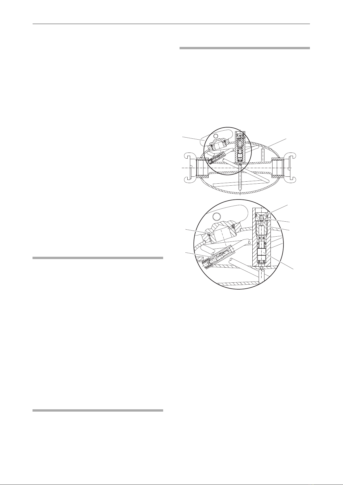
DANGER Pressurized lubricator hazard
When the lubricator is connected to a compressed
air line, the oil chamber is pressurized. If the filler
plug is loosened, there is a risk of oil being ejected
which can cause personal injury.
►Always disconnect the lubricator from the
compressed air line before loosening the filler plug.
© 2015 Construction Tools PC AB | No. 9800 1172 01a | 2015-04-10
Original instructions
6
CLG 10, 10 US, 30, 30 USSafety and operating instructions

DANGER Ejection of the oil dosage screw
hazard
The spring pin is a safety stop that prevents the oil
dosage screw from being ejected. If the oil dosage
screw comes loose it can be ejected and cause
personal injury.
►Never remove the spring pin.
►Never adjust oil dosage if the spring pin is missing.
WARNING Slipping, tripping and falling
hazards
There is a risk of slipping or tripping or falling, for
example tripping on the hoses or on other objects.
Slipping or tripping or falling can cause injury. To
reduce this risk:
►Always make sure that no hose or other object is
in your way or in any other person's way.
DANGER Electrical hazard
The machine is not electrically insulated. If the
machine comes into contact with electricity, serious
injuries or death may result.
►Never operate the machine near any electric wire
or other source of electricity.
►Make sure that there are no concealed wires or
other sources of electricity in the working area.
Maintenance, precautions
WARNING Machine modification
Any machine modification may result in bodily injuries
to yourself or others.
►Never modify the machine. Modified machines are
not covered by warranty or product liability.
►Always use original parts, working tools and
accessories.
►Change damaged parts immediately.
►Replace worn components in good time.
Storage, precautions
♦Keep the machine and tools in a safe place, out
of the reach of children and locked up.
7© 2015 Construction Tools PC AB | No. 9800 1172 01a | 2015-04-10
Original instructions
Safety and operating instructionsCLG 10, 10 US, 30, 30 US

Overview
To reduce the risk of serious injury or death to
yourself or others, read the Safety instructions
section found on the previous pages of this
manual before operating the machine.
Design and function
CLG 10 and CLG 30 are designed to lubricate
compressed air equipment, using mineral- or
synthetic oil. No other use is permitted.
Air flows into the lubricator through the inlet. Some
of the air flows into the oil chamber, via the check
valve, while the rest flows through the through-flow
pipe. When compressed air enters the oil chamber,
the oil becomes pressurized. This presses it up
through the oil pipe, through both the pipe opening
and small holes drilled in the pipe up to the valve
cone.
As the air through-flow pipe narrows just before the
point at which it is met by the oil duct (venturi tube),
there is an increase in air velocity and a decrease in
the air pressure.
The small pressure differential which now exists
between the oil chamber and the air through-flow
pipe (after the venturi), causes oil to be pressed up
into the through-flow pipe, via the valve cone.
The oil becomes atomised as it enters the
through-flow pipe, and is thus carried in the air supply
to the pneumatic machine.
Main parts
G
F
B
C
D
A
E
H
A. Valve cone
B. Stop screw
C. Spring pin
D. Oil dosage screw
E. Check valve
F. Filler plug
G. Oil chamber
H. Venting duct
Labels
The machine is fitted with labels containing important
information about personal safety and machine
maintenance. The labels must be in such condition
that they are easy to read. New labels can be ordered
from the spare parts list.
© 2015 Construction Tools PC AB | No. 9800 1172 01a | 2015-04-10
Original instructions
8
CLG 10, 10 US, 30, 30 USSafety and operating instructions

Safety label
XXX XX
Construction Tools AB
Atlas Copco
NACKA- SWEDEN
Designed by
Ordering No
XXXX XXXX XX
Type
Pmax bar(e)
XXX XX
20 (290psi)
FLOW
MAXMIN
A
B
C
A. Machine type
B. Maximum permitted compressed air pressure
C. The warning symbol together with the book
symbol means that the user must read the
safety and operating instructions before the
machine is used for the first time.
Installation
Hoses and connections
A
BC
D
A. Compressed air source
B. Water separator (optional)
C. Lubricator
D. Max. 3 m (10 ft) compressed air hose between
the lubricator and the pneumatic machine.
♦The maximum permissible air pressure, 20 bar (e)
(290 psi), must not be exceeded.
♦Blow any impurities out of the compressed air hose
before connecting it to the lubricator.
♦For the CLG 10 a hose with a minimum internal
diameter of 12.5-16.0 mm (
1
⁄
2
-
5
⁄
8
in.) must be used.
For the CLG 30 a hose with a minimum internal
diameter of 20-25 mm (
3
⁄
4
-1 in.) must be used.
♦There is a an arrow on the lubricator to indicate
the correct direction of air flow. When connecting
the lubricator, make sure that the arrow points in
the same direction as the air flow.
Lubrication
The lubricant is important for the pneumatic
machine’s function and has a great impact on the
useful service life. To guarantee good lubrication,
the length of the air hose between the lubricator and
the pneumatic machine must not exceed 3 meters.
Viscosity range
ViscosityTemperature °C (°F)
ISO VG 46–68
200-300 SUS
+15 to +50
(+59 to +122)
ISO VG 22–32
100-150 SUS
-20 to +15
(-4 to +59)
For the correct recommended lubrication oil, refer to
the Safety and operating instruction for the pneumatic
machine used together with the lubricator.
Oil adjustment
CLG 10 and 30 are delivered with the oil dosage
screw in the fully open position. The oil dosage screw
can be turned through a total of four complete turns.
It is steplessly adjustable.
To adjust the oil dosage, do the following:
♦Use a screwdriver to turn the oil dosage screw.
Clockwise reduces oil flow.
Anticlockwise increases oil flow.
♦Never remove the spring pin. If the oil dosage
screw become loose, the spring pin will prevent it
from blowing out of the lubricator.
♦Check the exhaust port of the pneumatic machine
to see that sufficent lubrication is being exhausted.
Operation
Operating
Filling the lubricator with oil
Always top up the lubricator with oil at the start of
the shift.
♦Switch off the air supply to the lubricator.
♦Vent the air line, to remove trapped air.
♦Clean around the outside of the filler plug to
prevent dirt from entering the lubricator.
9© 2015 Construction Tools PC AB | No. 9800 1172 01a | 2015-04-10
Original instructions
Safety and operating instructionsCLG 10, 10 US, 30, 30 US

♦Unscrew the filler plug by two turns, which opens
the venting duct and releases any remaining
compressed air in the lubricator.
♦Fill the lubricator with oil.
♦Re-fit and tighten the filler plug. The lubricator is
now ready for use.
Maintenance
Regular maintenance is a basic requirement for the
continued safe and efficient use of the lubricator.
Follow the maintenance instructions carefully.
♦Before starting maintenance on the lubricator,
clean it in order to avoid exposure to hazardous
substances.
♦Use only authorised parts. Any damage or
malfunction caused by the use of unauthorised
parts is not covered by warranty or product liability.
♦When cleaning mechanical parts with solvent,
comply with appropriate health and safety
regulations and ensure there is satisfactory
ventilation.
♦For major service to the lubricator, contact your
nearest authorised workshop.
Every day
Before undertaking any maintenance on the
lubricator, always switch off the air supply and then
disconnect the air hose from the lubricator.
♦Clean and inspect the lubricator and its functions
each day before work commences.
♦Conduct a general inspection for leaks and
damage.
♦Check that the claw couplings are tightened and
free from damage.
♦Change damaged parts immediately.
♦Replace worn components in good time.
♦Make sure that all the attached and related
equipment, such as hoses are properly
maintained.
Periodic maintenance
Once a year the lubricator must be dismantled and
all parts be cleaned and checked. This work must
be performed by authorised staff, trained for this task.
Assembly instruction
When reassembling the claw couplings on the
lubricator, apply LOCTITE® 577™ (LOCTITE is a
registered trademark of Henkel Corporation. 577 is
a trademark of Henkel Corporation).
Troubleshooting
If the lubricator is not working properly, check the
following points.
G
F
B
C
D
A
E
H
♦Check the oil level.
♦Check the valve cone (A), by first removing the
stop screw (B) and then inserting a pin into the
hole. Switch the air system on and off and feel if
the valve cone (A) is opening and closing correctly.
If the valve cone (A) is not working correctly,
disconnect the lubricator from the compressed air
line and bleed the oil chamber by loosening the
filler plug (F).
♦Remove the spring pin (C), oil dosage screw (D)
and valve cone (A). Clean the components and if
necessary, change the O-rings. When
reassembling, make sure that the spring pin (C)
is fitted.
♦Make sure that the check valve (E) is sealing
effectively, if not, clean or replace the check valve
(E).
♦Check for leakage around the filler plug (F).
© 2015 Construction Tools PC AB | No. 9800 1172 01a | 2015-04-10
Original instructions
10
CLG 10, 10 US, 30, 30 USSafety and operating instructions

♦Make sure that there is no dirt in the oil chamber
(G).
Storage
●Clean the lubricator properly before storage, in
order to avoid hazardous substances.
●If the lubricator is stored filled with oil, place it with
the filler plug upwards to prevent oil from leaking
out through the mouth of the air pipe.
●Always store the lubricator in a dry place.
Disposal
A used machine must be treated and disposed of in
such a way that the greatest possible portion of the
material can be recycled and any negative influence
on the environment is kept as low as possible, and
in respect to local restrictions.
11© 2015 Construction Tools PC AB | No. 9800 1172 01a | 2015-04-10
Original instructions
Safety and operating instructionsCLG 10, 10 US, 30, 30 US

Technical data
Machine data
Air flow range
l/s
(cfm)
Pressure drop at 6 bar and
max. flow
bar (e)
(psi)
Dosage (free air)
g/m3
Volume
l
(oz)
Weight
kg
(lb)Type
6-15
(13-32)
0.28
(4.06)
0.1-2.41.3
(44)
3
(6.6)
CLG 10
6-15
(13-32)
0.28
(4.06)
0.1-2.41.3
(44)
3
(6.6)
CLG 10 US
25-130
(53-275)
0.28
(4.06)
0.1-2.41.3
(44)
3
(6.6)
CLG 30
25-130
(53-275)
0.28
(4.06)
0.1-2.41.3
(44)
3
(6.6)
CLG 30 US
25-130
(53-275)
0.28
(4.06)
0.1-2.41.3
(44)
3
(6.6)
CLG 30 AUS
© 2015 Construction Tools PC AB | No. 9800 1172 01a | 2015-04-10
Original instructions
12
CLG 10, 10 US, 30, 30 USSafety and operating instructions


This manual suits for next models
3
Table of contents
Other Atlas Copco Lubrication System manuals
Popular Lubrication System manuals by other brands

LUBRIQUIP
LUBRIQUIP Trabon Series Operation and service instructions

Graco
Graco GREASE JOCKEY instructions

OEM Tools
OEM Tools 87042 Operating instructions and parts manual

Graco
Graco Mini Fire-Ball 225 Series Instructions-parts list

Wilkerson
Wilkerson L12 Installation & service instructions

Graco
Graco G3 Series instructions

DROPSA
DROPSA MiQueL EXT User Operating and Maintenance Manual

SKF
SKF Lubrigun 85100 Series User and maintenance instructions

Norgren
Norgren 10-028-037 Installation & maintenance instructions

Azbil
Azbil MC9 Series instruction manual

MP
MP L350D-2 Installation and Maintenance

LUBMANN
LUBMANN ALP01 product manual