REV. 02 2011 5 / 25
CHAPTER 2 – GENERAL INFORMATION
2.1 GENERAL SAFETY
xThe wheel balancing machine should only be used by duly authorized and trained personnel.
xThe wheel balancing machine should not be used for purposes other than those described in the
instruction manual.
xUnder no way should the wheel balancing machine be modified except for those modifications
made explicitly by THE MANUFACTURER.
xNever remove the safety devices. Any work on the machine should only be carried out by
specialist personnel.
xAvoid using strong jets of compressed air for cleaning.
xUse alcohol to clean plastic panels or shelves (AVOID LIQUIDS CONTAINING SOLVENTS).
xBefore starting the wheel balancing cycle, make sure that the wheel is securely locked on the
adapter.
xThe machine operator should avoid wearing clothes with flapping edges. Make sure that
unauthorized personnel do not approach the machine during the work cycle.
xAvoid placing objects inside the base as they could impair the correct operation of the machine.
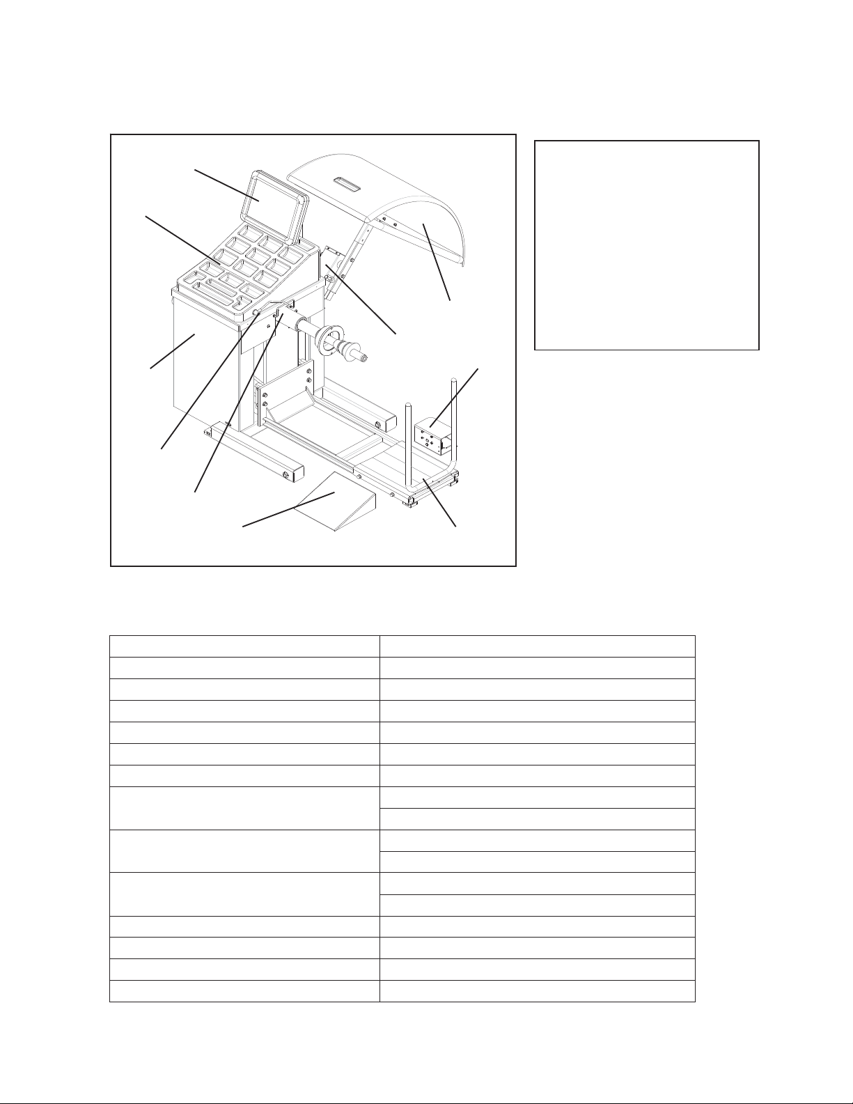
2.2 STANDARD SAFETY DVICES
xStop key for stopping the wheel under emergency conditions.
xA wheel guard of high impact plastic that is designed to prevent the counterweights from flying
out in any directing except toward the floor.
xA switch interlock system prevents the machine from starting if the guard is not lowered and
stops the wheel whenever the guard is raised.
2.3 INTENDED USE
xThis wheel balancer has been designed and manufactured exclusively for balancing wheel
with a maximum diameter of 1200mm and maximum weight of 200kg. The calibration system
is sufficient to cover different wheels from cars to trucks.
xIn particular THE MANUFACTURER cannot be held responsible for any damage caused
through the use of wheel balancer for purposes other than those specified in this manual, and
therefore inappropriate, incorrect and unreasonable.
2.4 GENERAL CHARATERISTICS
xAutomatic braking after spin
xAutomatic start/stop when the hood is lowered/raised
xSTOP pushbutton to stop the machine immediately
xStatic and dynamic balancing modes
xFour ALU modes
xRapid optimization (OPT)
xSelf-diagnosis
xSelf-calibration
xExceptional stability in reading the unbalance between planes
xDisplay in grams or ounces, in mm or inch
xAnchor-down installation unnecessary