7
Step 2 (A1): Installation of L-shaped jaws (method 1)
Screw 3*6mm
L-shaped jaws
H2.5 hexagonal
plate hand
Suppo column assembly
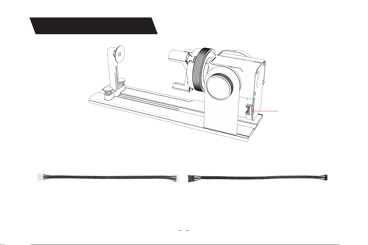
5.Installation guide
Key points of operation: the sphere should stick to the three jaws as far as possible, and then The
suction cup of the rear suppo column is attached to the sphere, and then tightened screw. When
disassembling the ball, you can put the chuck Loosen, then move the suppo column back.
Note:
1. When engraving a cued suace, take the average value of the diameter/circumference of the
actual engraving range of the measured object (the average value of the left, middle and right of
the engraving range position)
2. When tilting and engraving, adjust the appropriate position of engraving by rotating the button
3. Round bottom object engraving