Atop EH3408ls User manual

Industrial Managed
Ethernet Switch
User Manual
Page 1of 49
Industrial Managed
Ethernet Switch
User Manual
V0.1
April 18th, 2022
Series covered by this manual:
EH3408ls, EH3408lu, EH3408s, EH3408u,
* The user interface on these products may be slightly different
from the one shown on this user manual
Atop Technologies, Inc.

Industrial Managed
Ethernet Switch
User Manual
Page 2of 49
This PDF Document contains internal hyperlinks for ease of navigation.
For example, click on any item listed in the Table of Contents to go to that page.
Published by:
Atop Technologies, Inc.
2F, No. 146, Sec. 1, Tung-Hsing Rd,
30261 Chupei City, Hsinchu County
Taiwan, R.O.C.
Tel: +886-3-550-8137
Fax: +886-3-550-8131
www.atoponline.com

Industrial Managed
Ethernet Switch
User Manual
Page 3of 49
Important Announcement
The information contained in this document is the property of Atop Technologies, Inc., and is supplied for the sole
purpose of operation and maintenance of Atop Technologies, Inc., products.
No part of this publication is to be used for any other purposes, and it is not to be reproduced, copied, disclosed,
transmitted, stored in a retrieval system, or translated into any human or computer language, in any form, by any
means, in whole or in part, without the prior explicit written consent of Atop Technologies, Inc.,
Offenders will be held liable for damages and prosecution.
All rights, including rights created by patent grant or registration of a utility model or design, are reserved.
Disclaimer
We have checked the contents of this manual for agreement with the hardware and the software described. Since
deviations cannot be precluded entirely, we cannot guarantee full agreement. However, the data in this manual is
reviewed regularly and any necessary corrections will be included in subsequent editions.
Suggestions for improvement are welcome. All other product’s names referenced herein are registered trademarks
of their respective companies.
Preface
This manual contains some advanced network management knowledge, instructions, examples, guidelines, and
general theories. The contents are designed to help users manage the switch and use its software, a background in
general theory is a must, when reading it. Please refer to the Glossary for technical terms and abbreviations.
Who Should Use This User Manual
This manual is to be used by qualified network personnel or support technicians who are familiar with network
operations, and might be useful for system programmers or network planners as well. This manual also provides
helpful and handy information for first time users. For any related problems, please contact your local distributor. If
they are unable to assist you, please redirect your inquiries to www.atoponline.com .
Warranty Period
Atop technology provides a limited 5-year warranty for managed Ethernet switches.
Documentation Control
Author:
Saowanee Saewong
Revision:
0.1
Revision History:
Initial
Creation Date:
17 December 2021
Last Revision Date:
17 April 2022
Product Reference:
Industrial Lite-managed Switch
Document Status:
Released

Industrial Managed
Ethernet Switch
User Manual
Page 4of 49
Table of Contents
1Introduction .................................................................................................................7
1.1 Introduction to Industrial Managed Switch........................................................................................7
1.2 Software Features............................................................................................................................8
2Configuring with a Web Browser ..................................................................................9
2.1 Web-based Management Basics.....................................................................................................9
2.1.1 Default Factory Settings...................................................................................................................9
2.1.2 Login Process and Main Window Interface....................................................................................10
2.2 Information .....................................................................................................................................12
2.2.1 Information feature.........................................................................................................................12
2.2.2 Connection feature.........................................................................................................................14
2.2.3 System Log feature........................................................................................................................15
2.3 Configuration..................................................................................................................................17
2.3.1 IP Setting feature............................................................................................................................17
2.3.2 System Time feature......................................................................................................................18
2.3.3 Port Status feature .........................................................................................................................21
2.4 Diagnostic.......................................................................................................................................23
2.4.1 System Log feature........................................................................................................................23
2.4.2 Rmon History feature .....................................................................................................................24
2.4.3 Port Statistics feature.....................................................................................................................25
2.4.4 LLDP feature..................................................................................................................................26
2.4.5 Warning/Alarm feature ...................................................................................................................27
2.4.6 Log Event feature...........................................................................................................................29
2.5 Security ..........................................................................................................................................30
2.5.1 Storm Control feature.....................................................................................................................30
2.5.2 VLAN Table feature........................................................................................................................32
2.6 RSTP..............................................................................................................................................34
2.7 Management ..................................................................................................................................36
2.7.1 Account feature ..............................................................................................................................36
2.7.2 HTTPS feature ...............................................................................................................................37
2.7.3 SNMP feature.................................................................................................................................37
2.8 Maintenance...................................................................................................................................41
2.8.1 Firmware feature............................................................................................................................41
2.8.2 Backup/Restore feature .................................................................................................................43
2.8.3 Backup/Restore (storage device) feature.......................................................................................44
2.8.4 Factory Default feature...................................................................................................................46
2.8.5 Reboot feature................................................................................................................................47
2.8.6 Apply All feature.............................................................................................................................48
2.9 Logout ............................................................................................................................................48
Table of Figures
Figure 2.1 IP Address for Web-based Setting..........................................................................................................10
Figure 2.2 Login Prompt...........................................................................................................................................10
Figure 2.3 Default Web Interface for EH3408-SD....................................................................................................11
Figure 2.4 Function Bar on Top of Web GUI ...........................................................................................................11
Figure 2.5 Information Function...............................................................................................................................12
Figure 2.6 Information Feature.................................................................................................................................13
Figure 2.7 System Setting Management Pop-up Window.......................................................................................14
Figure 2.8 Connection Feature ................................................................................................................................14
Figure 2.9 IP Network Setting Pop-up Window........................................................................................................14

Industrial Managed
Ethernet Switch
User Manual
Introduction
Page 5of 49
Figure 2.10 Log Feature...........................................................................................................................................15
Figure 2.11 System Log Setting Pop-up Window ....................................................................................................16
Figure 2.12 System Setting or Configuration Function ............................................................................................17
Figure 2.13 IP Setting Feature.................................................................................................................................17
Figure 2.14 IP Setting Pop-up Window....................................................................................................................18
Figure 2.15 System Time Feature............................................................................................................................19
Figure 2.16 System Time and SNTP Pop-up Window.............................................................................................20
Figure 2.17 Port Status Feature...............................................................................................................................21
Figure 2.18 Port Control Pop-up Window ................................................................................................................22
Figure 2.19 Diagnostic Function on Menu Bar.........................................................................................................23
Figure 2.20 System Log Feature..............................................................................................................................23
Figure 2.21 System Log Setting Pop-up Window ....................................................................................................24
Figure 2.22 System Log Clear Pop-up Window.......................................................................................................24
Figure 2.23 Rmon History Feature...........................................................................................................................25
Figure 2.24 Port Statistics (Overview) Feature........................................................................................................25
Figure 2.25 LLDP Feature........................................................................................................................................26
Figure 2.26 LLDP Setting Pop-up Window ..............................................................................................................27
Figure 2.27 Warning/Alarm Feature.........................................................................................................................28
Figure 2.28 Warning/Alarm Setting Pop-up Window ...............................................................................................28
Figure 2.29 Log Event Feature ................................................................................................................................29
Figure 2.30 Log Event Setting Pop-up Window.......................................................................................................29
Figure 2.31 SYSLOG Event Drop-down Selection ..................................................................................................30
Figure 2.32 Security Function ..................................................................................................................................30
Figure 2.33 Storm Control Feature ..........................................................................................................................31
Figure 2.34 Storm Control Setting Pop-up Window.................................................................................................31
Figure 2.35 VLAN Table Feature .............................................................................................................................32
Figure 2.36 VLAN Setting Pop-up Window..............................................................................................................33
Figure 2.37 RSTP Feature.......................................................................................................................................34
Figure 2.38 RSTP Setting Pop-up Window..............................................................................................................35
Figure 2.39 Management Function ..........................................................................................................................36
Figure 2.40 Accout Feature......................................................................................................................................36
Figure 2.41 Accout/User List Pop-up Window .........................................................................................................36
Figure 2.42 HTTPS Feature.....................................................................................................................................37
Figure 2.43 HTTPS Setting Pop-up Window ...........................................................................................................37
Figure 2.44 SNMP Feature ......................................................................................................................................38
Figure 2.45 SNMP Agent Mode and SNMP v1/v2c Community Management........................................................38
Figure 2.46 SNMP v1/v2c Trap Management..........................................................................................................39
Figure 2.47 SNMP v3 Feature .................................................................................................................................39
Figure 2.48 SNMP v3 Configuration Pop-up Window..............................................................................................40
Figure 2.49 SNMP v3 Trap Server Setting Pop-up Window....................................................................................40
Figure 2.50 Maintenace Function.............................................................................................................................41
Figure 2.51 Firmware Feature..................................................................................................................................41
Figure 2.52 Upgrade Firmware Pop-up Window......................................................................................................42
Figure 2.53 Select Image Bank Pop-up Window .....................................................................................................42
Figure 2.54 Backup/Restore Feature.......................................................................................................................43
Figure 2.55 Backup Pop-up Window........................................................................................................................43
Figure 2.56 Restore Pop-up Window.......................................................................................................................43
Figure 2.57 Backup/Restore (storage device) .........................................................................................................44
Figure 2.58 USB Auto Backup Pop-up Window for EH3408lu and EH3408u .........................................................44
Figure 2.59 SD Auto Backup Pop-up Window for EH3408ls and EH3408s............................................................45
Figure 2.60 Backup to USB Storage Device Pop-up Window for EH3408lu and EH3408u....................................45
Figure 2.61 Backup to Micro-SD Storage Device Pop-up Window for EH3408ls and EH3408s.............................45
Figure 2.62 Restore from USB Storage Device Pop-up Window for EH3408lu and EH3408u...............................46
Figure 2.63 Restore from Micro-SD Storage Device Pop-up Window for EH3408ls and EH3408s........................46
Figure 2.64 Option of Auto-Restore from USB Pop-up Window for EH3408lu and EH3408u.................................46
Figure 2.65 Option of Auto-Restore from Micro-SD Pop-up Window for EH3408ls and EH3408s .........................46
Figure 2.66 Factory Default Feature........................................................................................................................47
Figure 2.67 Factory Default Pop-up Window...........................................................................................................47
Figure 2.68 Reboot Feature.....................................................................................................................................47

Industrial Managed
Ethernet Switch
User Manual
Introduction
Page 6of 49
Figure 2.69 Reboot Pop-up Window........................................................................................................................48
Figure 2.70 Apply All Feature...................................................................................................................................48
Figure 2.71 Apply All Pop-up Window......................................................................................................................48
Figure 2.72 Logout Feature......................................................................................................................................48
Table of Tables
Table 2.1 Descriptions of the information features...................................................................................................13
Table 2.2 Description of IP Network Settings ..........................................................................................................15
Table 2.3 Description of Log Entry...........................................................................................................................15
Table 2.4 Description of System Log Setting Pop-up Window ................................................................................16
Table 2.5 Description of IP Setting Pop-up Window................................................................................................18
Table 2.6 Description of System Time and SNTP Pop-up Window.........................................................................20
Table 2.7 Description of Port Control Pop-up Window ............................................................................................22
Table 2.8 Description of Columns in LLDP Neighbor Info Table .............................................................................26
Table 2.9 Description of LLDP Protocol Setting Pop-up Window............................................................................27
Table 2.10 Description of Root Bridge Information ..................................................................................................35

Industrial Managed
Ethernet Switch
User Manual
Introduction
Page 7of 49
1Introduction
1.1 Introduction to Industrial Managed Switch
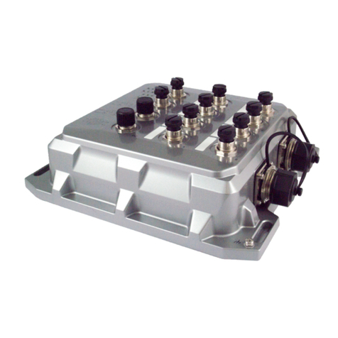
Atop’s EH (Ethernet Switching Hub) 3408 series are product lines of cost-effective switch for industrial networking
where simple managing is required. This lite-managed switch provides key features that most users need without
those unnecessary features. The device’s easy web configuration includes functions like SNMP, warning realy-out,
Syslog and a user-friendly web GUI, which is especially useful when creating a compatible network for industry 4.0
automation equipment, setting up Quality of Service (QoS) and Virtual Local Area Network (VLAN) to run industrial
protocols such as Profinet and Ethernet/IP. Furthermore, multiple account levels allow optimal management with
different users accessing different operations.
All these features are packed in a slim and sturdy enclosure that fits in cabinets with limited space, while protecting
against environmental hazards according to CE, FCC and UL standards. Two operation ranges are available for your
choice: -10 C to +60 C for regular climates and -40 C to +75 C for extreme ones. Cyber protection is not overlooked
either. The EH3408 series supports security features based on the IEC62443-4-2 standard. An EH3408 switch comes
with either USB or Micro-SD card support so that device configurations can be automatically backed up on a regular
basis. In the unlikely event of device failure, simply transfer the USB or SD card to a new device to restore all original
configurations.
Note:
Throughout the manual, the symbol * indicates that more detailed information of the subject will be provided at the
end of this book or as a footnote.

Industrial Managed
Ethernet Switch
User Manual
Introduction
Page 8of 49
1.2 Software Features
Atop’s industrial lite-managed switches come with a wide range of network protocols and software features. These
protocols and software features allow the network administrator to implement security and reliability into their
network. These features enable Atop’s switches to be used in safety applications, and factory and process
automation. The followings are the list of protocols and software features.
•User Interfaces
oWeb browser
oTelnet Console
oSerial Console
•Dynamic Host Configuration Protocol (DHCP) Server/Relay/Client with Option 66/67
•Time Synchronization
oNetwork Time Protocol (NTP) Server/Client
oSimplified Network Time Protocol (SNTP)
•Quality of Service (QoS) Traffic Regulation
•Simple Network Management Protocol (SNMP) v1/v2/v3 (with MD5 Authentication and DES encryption)
•Spanning Tree Protocol (STP)/Rapid Spanning Tree Protocol (RSTP
•Virtual Local Area Network (VLAN)
•IEEE 802.1x / Extensible Authentication Protocol (EAP) / Remote Authentication Dial-In User Service
(RADIUS) / Terminal Access Controller Access-Control System (TACACS+)
•Alarm System (with E-mail Notification or Relay Output)

Industrial Managed
Ethernet Switch
User Manual
Configuring with a Web
Browser
Page 9of 49
2Configuring with a Web Browser
Chapter 2 explains how to access the industrial lite-managed switch for the first time. There are three ways to
configure this Ethernet Switch:
1. Web browser
2. Telnet console
3. Serial console
The web browser and the telnet console methods allow users to access the switch over the Internet or the Ethernet
LAN, while the serial console method requires a serial cable connection between the console and the switch. There
are only a few differences among these three methods. Users are recommended to use the web browser method to
configure the system because of its user-friendly interface.
2.1 Web-based Management Basics
Users can access the managed switch easily using their web browsers (Internet Explorer 8 or 11, Firefox 44, Chrome
48 or later versions are recommended). We will proceed to use a web browser to introduce the managed switch’s
functions.
2.1.1 Default Factory Settings
Below is a list of default factory settings. This information will be used during the login process. Make sure that the
computer accessing the switch has an IP address in the same subnet and the subnet mask is the same.
IP Address: 10.0.50.1
Subnet Mask: 255.255.0.0
Default Gateway: 0.0.0.0
User Name: admin
Password: default

Industrial Managed
Ethernet Switch
User Manual
Configuring with a Web
Browser
Page 10 of 49
2.1.2 Login Process and Main Window Interface
Before users can access the configuration, they have to log in. This can simply be done in three steps.
1. Launch a web browser.
2. Type in the switch’s IP address (e.g. http://10.0.50.1), as shown in Figure 2.1).
Figure 2.1 IP Address for Web-based Setting
3. A login prompt will be shown as in Figure 2.2. You can enter the default user name and password given
in previous page. Then, click the Login button to login to the web interface.
Figure 2.2 Login Prompt
After the login process, the main interface will show up as shown in Figure 2.3. Under the Atop Technologies’ Logo,
there are basic information about the device which are Model Name,Kernel Version,Firmware Version,SerialNumber
(SerialNum) and MAC Address. The main configuration menu of the EH3408 series is listed as the group of green
circular icons called function bar under the basic information of the device. Each configuration web page can be
accessed by clicking on corresponding circular icon of the function bar. The user can move the pointer of the mouse
on top of particular circular icon to see the tooltip that indicates the name of the icon.

Industrial Managed
Ethernet Switch
User Manual
Configuring with a Web
Browser
Page 11 of 49
Figure 2.3 Default Web Interface for EH3408-SD
The function bar on the top of the web GUI is shown in Figure 2.4. There are 8 functions in the bar from the left side
to the right side which are functions to manage Information, Configuration, Diaganostic, Security, RSTP,
Management, Maintetance, and Logout. Note that there is a picture of the front panel of the EH3408 device on the
left side of the screen under the function bar. This front panel of the manage switch display the LEDs of power, fault,
port link status,etc. Note that in this case the Port 4 is highlighted in green,indicating that the port is being connected.
Detailed explanations of each function icon will be addressed later as necessary.
Figure 2.4 Function Bar on Top of Web GUI

Industrial Managed
Ethernet Switch
User Manual
Configuring with a Web
Browser
Page 12 of 49
2.2 Information
To help users become familiar with the device, the Information function icon denoted by question mark provides
important details of the managed switch. This is also the main welcome screen once the user has logged in. The
details make it easier to identify different switches connected to the network. The information web page is separated
into three boxes or features called Information, Connection and Log as shown in Figure 2.5. Each feature usually
includes a gear icon next to the feature’s name. This gear for particular feature can be used to bring up a pop-up
window for managing configuration of that particular feature.
Figure 2.5 Information Function
2.2.1 Information feature
This feature provides basic system information of Atop’s industrial managed switch. The user can check the device
description which includes System Name, System Description, System Location, System Contact, and System OID
as shown in Figure 2.6. Additionally, the Model Name, Loader Version, Kernel Version, and Firmware Version are
listed. Note that Atop’s firmware generally consists of kernel version and firmware version. At the bottom of this
section, the Uptime and the Current Date & Time of the device are displayed. Table 2.1 summarizes the description
of each basic information.

Industrial Managed
Ethernet Switch
User Manual
Configuring with a Web
Browser
Page 13 of 49
Figure 2.6 Information Feature
Table 2.1 Descriptions of the information features
Label
Description
Factory Default
System Name
Specifies a particular role or application of different switches. The
name entered here will also be shown in Atop’s Device Management
Utility. Max. 63 Char.
(Model name)
System
Description
Detailed description of the unit. Max. 63 Characters.
Managed Switch +
(Model name)
System Location
Location of the switch. Max. 63 Characters.
Switch Location
System Contact
Provides contact information for maintenance. Enter the name of
whom to contact in case a problem occurs. Max. 63 Characters.
www.atop.com.tw
System OID
System’s SNMP object identification (OID) number
-
Model name
The device’s complete model name
(Model name)
Loader Version
The bootloader version of the device
-
Kernel Version
The current kernel version of the device
-
Firmware Version
The current firmware version of the device
-
Uptime
The duration of time since the device was started in days, hours, and
minutes
-
Current Date &
Time
The current date and time of the device
-
To change or configure fields under the Information feature, the user can click on the gear icon to bring up a pop-up
window called System Setting as shown in Figure 2.7. On this window, the user can configure System Name, System
Description, System Location and System Contact. After you finished, clicking on the Save Changes button to save
any changes or clicking on the Save Changes and Apply button to save and apply the setting.
Remark: The management pages provide two ways to save the changes of the configuration: Save Changes and
Save Changes and Apply buttons. The former button will only save the new setting whole the latter button will save
and then apply the setting so that it will be in effect immediately.

Industrial Managed
Ethernet Switch
User Manual
Configuring with a Web
Browser
Page 14 of 49
Figure 2.7 System Setting Management Pop-up Window
2.2.2 Connection feature
The Connection feature displays the current setting of the network configuration of the manage switch which are the
status of DHCP Client, the IP Address, and the sub-Netmask as shown in Figure 2.8. To change network
configuration, the user can click on the gear icon to bring up the IP Network Setting pop-up window as shown in
Figure 2.9. The user can choose to enable or disable the Dynamic Host Configuration Protocol (DHCP) on the device
as the DHCP client by selecting the corresponding drop-down list. If the DHCP Client is enabled, the manage switch
will obtain the IP address configuration from another server in the network. If the DHCP Client is disabled, the user
will have to enter the IPv4 Address, Subnet Mask, Gateway IP, DNS Servers 1 and DNS Servers 2. After you finished,
clicking on the Save Changes button to save any changes or clicking on the Save Changes and Apply button to save
and apply the setting. Table 2.2 summarizes the device information setting descriptions and corresponding default
factory settings.
Figure 2.8 Connection Feature
.
Figure 2.9 IP Network Setting Pop-up Window

Industrial Managed
Ethernet Switch
User Manual
Configuring with a Web
Browser
Page 15 of 49
Table 2.2 Description of IP Network Settings
Label
Description
Factory Default
DHCP Client
By selecting Enabled, an IP address and related fields
will be automatically assigned. Note the fields below
will be grey out. Otherwise, users can select Disabled
and continue to set up the static IP address and
related fields manually.
Disabled
IPv4 Address
The current IPv4 address of the device. Users can set a
new static IP address for the device.
10.0.50.1
Subnet Mask
Display current Subnet Mask or set a new subnet mask
255.255.0.0
Gateway IP
Show current Gateway IP address or user can set a
new one
0.0.0.0
DNS Server 1
Show current primary DNS IP address to be used by
your network or user can set a new one
0.0.0.0
DNS Server 2
Show current secondary DNS IP address to be used by
your network or user can set a new one
0.0.0.0
2.2.3 System Log feature
The Log feature at the buttom of the Information function shows a table of at least 5 system logs as shown in Figure
2.10. Each log entry includes Date, Time, Up Time, and Event description. Note that the log entries are sorted by date
and time. Table 2.3 provides explanation of each column in the Log table.
Figure 2.10 Log Feature
Table 2.3 Description of Log Entry
Label
Description
Date
Indicate the system date of the occurred event
Time
Indicate the time stamp that this event occurred
Up Time
Indicate how long the system (managed switch) has been up since this event occurred
Event
Details description of this event
If the user would like to configure the System Log Setting, the user can click on the gear icon to bring up a System
Log Setting pop-up window as shown in Figure 2.11. On this window, the user can enable or disable sending log to a
log server. If the user enables the Log to Server option by choosing from the pull-down menu, the user will have to
specify the Log’s Server IP Address and Server Service Port in the next two fields. After you finished, clicking on the
Save Changes button to save any changes or clicking on the Save Changes and Apply button to save and apply the
setting.

Industrial Managed
Ethernet Switch
User Manual
Configuring with a Web
Browser
Page 16 of 49
Figure 2.11 System Log Setting Pop-up Window
Table 2.4 Description of System Log Setting Pop-up Window
Label
Description
Factory Default
Log to Server
Enabled: Enable Syslog Server.
Disabled: Disable Syslog Server.
If enabled, all recorded log events will be sent to the remote
System Log server.
Disable
Server IP Address
Set the IP address of Syslog server
0.0.0.0
Server Service Port
Set the service port number of System Log server.
Range from Port 1 to Port 65535.
514

Industrial Managed
Ethernet Switch
User Manual
Configuring with a Web
Browser
Page 17 of 49
2.3 Configuration
The Configuration or System Setting function is the second icon from the left. It is the circular icon with the pictures
of wrench and screw driver. There are three features under the Configuration or System Setting function which are
IP Setting, System Time, and Port Status as shown in Figure 2.12.
Figure 2.12 System Setting or Configuration Function
2.3.1 IP Setting feature
The IP Setting feature summarizes the current IP configuration of the manage switch. This web page as shown in
Figure 2.13 displays information such as DHCP Client, IPv4 Address, Subnet Mask, Gateway IP, DNS Servers
1, and DNS Servers 2. By clicking on the gear icon next to the IP Setting title, the user can bring up the IP Setting
pop-up window as shown in Figure 2.14. Table 2.5 summarizes each field in the IP Setting pop-up window. After
you finished, clicking on the Save Changes button to save any changes or clicking on the Save Changes and Apply
button to save and apply the setting.
Figure 2.13 IP Setting Feature

Industrial Managed
Ethernet Switch
User Manual
Configuring with a Web
Browser
Page 18 of 49
Figure 2.14 IP Setting Pop-up Window
Table 2.5 Description of IP Setting Pop-up Window
Label
Description
Factory Default
DHCP Client
By selecting Enabled, an IP address and related fields
will be automatically assigned. Note the fields below
will be grey out. Otherwise, users can select Disabled
and continue to set up the static IP address and
related fields manually.
Disabled
IPv4 Address
The current IPv4 address of the device. Users can set a
new static IP address for the device.
10.0.50.1
Subnet Mask
Display current Subnet Mask or set a new subnet mask
255.255.0.0
Gateway IP
Show current Gateway IP address or user can set a
new one
0.0.0.0
DNS Server 1
Show current primary DNS IP address to be used by
your network or user can set a new one
0.0.0.0
DNS Server 2
Show current secondary DNS IP address to be used by
your network or user can set a new one
0.0.0.0
2.3.2 System Time feature
The second feature under the system setting function is the System Time feature as shown in Figure 2.15. Atop’s
industrial managed switch has internal calendar (date) and clock (or system time) which can be set manually or
automatically. This web page shows the configuration of System Time and Simple Network Time Protocol (SNTP).
The first line in the figure indicates the Current Date & Time. The next line shows the current Time Zone. Then, the
Mode option indicates the current mode of system time setting. This could be manual or automatic. The next three
fields are NTP Server IP, SNTP Server IP, and NTP Server Setting. Finally, the last four lines on this web page provides
information about the daylight time saving status, which are Daylight Saving State, Start Date, End Date, and Offset.

Industrial Managed
Ethernet Switch
User Manual
Configuring with a Web
Browser
Page 19 of 49
Figure 2.15 System Time Feature
To configure system time and SNTP, the user can click on the gear icon in Figure 2.15. This will bring up the System
Time and SNTP pop-up window as shown in Figure 2.16. The users have options to configure Current Date & Time
manually by choosing the pull-down menu for Mode to Manual. In manual mode as shown in Figure 2.16, the user
can enter the Date and Time in the formats of YYYY:MM:DD and hh:mm:ss.
For automatically date and time setting, the users can enable Simple Network Time Protocol (SNTP) by selecting the
pull-down manu for Mode as Automatic. Next, the user can select the Time Zone from the drop-down list. Then, the
users must enter the NTP Server 1, NTP Server 2, and NTP Server 3 which will be used as the reference servers to
synchronize date and time to. Next, the SNTP Server IP’s address can be specified.
The managed switch can become a network time protocol server for the local devices by enabling NTP Server Setting
option. The user can either enable or disable this option.
Finaly, the user has an option to enable or disable the Daylight Saving State. If the manage switch is deployed in a
region where daylight saving time is practiced (see note below for explanation), please check the Enable option for
Daylight Saving State.Then, the users will have to enter the Start Date, End Date, and Offset in hour(s). After you
finished, clicking on the Save Changes button to save any changes or clicking on the Save Changes and Apply button
to save and apply the setting. Table 2.6 summarizes the description of fields in System Time and SNTP pop-up
window.
*Note:
- Daylight Saving Time: In certain regions (e.g. US), local time is adjusted during the summer season in order to
provide an extra hour of daylight in the afternoon, and one hour is usually shifted forward or backward.
- SNTP: Simple Network Time Protocol is used to synchronize the computer systems’clocks with a standard NTP
server. Examples of two NTP servers are time.nist.gov and time-A.timefreq.bldrdoc.gov.

Industrial Managed
Ethernet Switch
User Manual
Configuring with a Web
Browser
Page 20 of 49
Figure 2.16 System Time and SNTP Pop-up Window
Table 2.6 Description of System Time and SNTP Pop-up Window
Label
Description
Factory Default
Current Date &
Time
Display the current date and time on the manage
switch
None
Mode
This option can be set as Manual or Automatic date
and time setting
Manual
Date
Allows local date configuration in YYYY/MM/DD
format
None
Time
Allows local time configuration in local hh:mm:ss
format
None
Time Zone
The user can choose the current local time from the
drop-down list.
(UTC+00:00) England
Daylight Saving
Enable or disable Daylight Saving Time function
Unchecked
NTP Server IP 1
Sets the first IP or Domain address of NTP Server.
time.nist.gov
NTP Server IP 2
Sets the second IP or Domain address of NTP Server.
Switch will locate the 2nd NTP Server if the 1st NTP
Server fails to connect.
Time-A.timefreq.bldrdoc.gov
NTP Server IP 3
Sets the third IP or Domain address of NTP Server.
Switch will locate the 3rd NTP Server if the 1st and 2nd
NTP Servers fail to connect.
SNTP Server IP
Sets the IP or Domain address of SNTP Server.
NTP Server
Setting
This option can enable or disable network time
protocol (NTP) daemon inside the managed switch
which allows other devices in the network to
synchronize their clock with this managed switch
using NTP.
Disable
This manual suits for next models
3
Table of contents
Other Atop Switch manuals

Atop
Atop EH7506-4PoE-2SFP User manual

Atop
Atop EH2316 Series Manual

Atop
Atop EHG7504 Manual

Atop
Atop EHG2408 Series Manual

Atop
Atop EH3305 Series User manual

Atop
Atop EHG3005 Series Manual

Atop
Atop EHG75 series User manual

Atop
Atop EHG7305 Series User manual

Atop
Atop CloudProof M1000 serious User manual

Atop
Atop EMG8508 Series Manual
Popular Switch manuals by other brands

Wildix
Wildix WSG18SF user manual

Orolia
Orolia EdgeSync user manual

Cables to Go
Cables to Go TruLink 35555 user manual

Murphy
Murphy Selectronic SS300 Series Installation and operation instructions

National Instruments
National Instruments SCXI-1127 Getting started guide

Linksys
Linksys EF24G2 - EtherFast Dual Gigabit Specifications