Audion Elektro D 555 NH User manual

AUDION ELEKTRO ®
ALL-IN-SEALER
D 555 NH
MANUAL
D555 NH ENG Rev06

2
All rights reserved. Nothing from this edition is allowed to be copied and/or made public by means of print, photo copy or any other way
without previous written permission of AUDION L KTRO.
AUDION L KTRO reserves the right to change spareparts and/or specifications without previous notice. Contents of this manual can
also be changed without previous warning.
AUDION L KTRO cannot be hold responsible for eventual damage caused by specifications deviating from the standard model.
Although extreme care has been exercised during writing this manual, AUDION L KTRO will not accept any liability for eventual
errors in this manual and/or for the consequences of (mis)interpretation of the contents.
AUDION L KTRO is not responsible for damage or problems which result from the use of other than the original spareparts.
If this manual has not been supplied with instructions for certain repairs, adjustments and maintenance, you should contact your dealer
of AUDION L KTRO.

3
CONTENTS
1 To unpack the All-in sealer 4
2 Safety instructions 4
3 General description 5
4 Dimensions 5
5 Operation panel 6
6 Installation 7
6 1 Description of workplace 7
6 2 Connecting ALL-IN-SEALER 7
6 2 1 Adjusting height transport belt 7
6 2 2 Connecting to power supply 7
6 3 Adjusting seal temperature/speed 8
6 4 Cool run 8
6 5 Standby 8
6 6 Preparation for use 9
6 7 Emergency stop 9
7 Specifications 9
7 1 Operational specifications 9
7 2 Applocations not allowed 9
8 Maintenance 10
8 1 Maintenance and adjusting ALL-IN-SEALER 11
8 2 Heating elements 12
8 2 1 Adjust heating plates 12
8 2 2 Replace heating elements 12
8 3 PTFE-belts Fout! Bladwijzer niet gedefinieerd.
8 3 1 Adjust PTFE-belts 12
8 3 2 Replace PTFE-belts 13
8 4 V-belts 14
8 4 1 Replace v-belts 14
8 5 Pressure roller 14
8 6 Transport belt 15
8 6 1 Adjust transport belt 15
8 7 Motor Set-up 16
8 8 Correction factor 16
8 9 Reset to factory settings 16
8 10 Print jumpers 17
9 Technical data 17
10 Problems and solutions 17
11 Recommended spare parts 18
12 Discard the All-in 19
13 Conditions of guarantee 19
13 1 Liability 19
13 2 Guarantee 19
14 Electrical circuit Appendix A1
15 Exploded views Appendix B1

4
1 To unpack the All-in sealer
Check during the unpacking of the All-in sealer if all parts mentioned below are present
- ALL-IN-SEALER D 555 NH
- Infeed guide
- Rubber feet (4x)
- Spare PTFE-belt (2x)
- Wrench 10 / 13 to mount rubber feet
- Screw driver to open front cover
- Allan key (2x) gearbox
- Manual
The D 555 NH is mounted on a wooden plate and packed in a carton box The machine should be picked
up, out of the carton box, by two persons Place the D 555NH on a work table Disassamble the wooden
plate and mount the four rubber feet
Check the data on the identification plate of the machine and record the information on the identification
plate (fig 1) in the figure below
The All-in sealer has been packed in a carton box We recommend you to retain the carton box for future
transport
2 Safety instructions
Read the manual carefully before any operation on the All-in!
− Check, before the All-in is put into operation, whether the data on the identification plate corresponds
with the Voltage (V), Power Rating (W) and Frequency (Hz) of the local power supply
− If the All-in is not to be used for a long period of time, disconnect the power cord from the mains
supply
− Remove the power cord from the mains supply before any maintenance takes place on the All-in
Beware of the danger of an electric shock
− Do not use water, abrasives, chemicals or other liquids for cleaning the All-in See Chapter 8
− If in doubt about the correct operation of the All-in, immediately disconnect the power cord and consult
maintenance personnel
− Have repairs done by skilled maintenance personnel only
− Should liquid or an object fall into the All-in, immediately remove the power cord from the mains
supply and have the All-in checked by a skilled person before using it again
− Only use replacements parts provided by Audion Elektro
− Do not use the All-in to seal other materials then recommended by Audion Elektro (see chapter 3)
Fig 1
5
3 General description
The ALL-IN-SEALER is a stand-alone continuous sealing machine
The width of the bags to be sealed is unlimited The sealing temperature can easily be set The
automatic temperature control keeps the temperature fixed at the same level during operation
The ALL-IN-SEALER is suitable for sealing "ready to hand" bags of Polyethylene (PE), Polypropylene
(PP), thin PVC's and various laminates
The All-in is standard supplied with a touch-panel and a digital display for the temperature and the speed
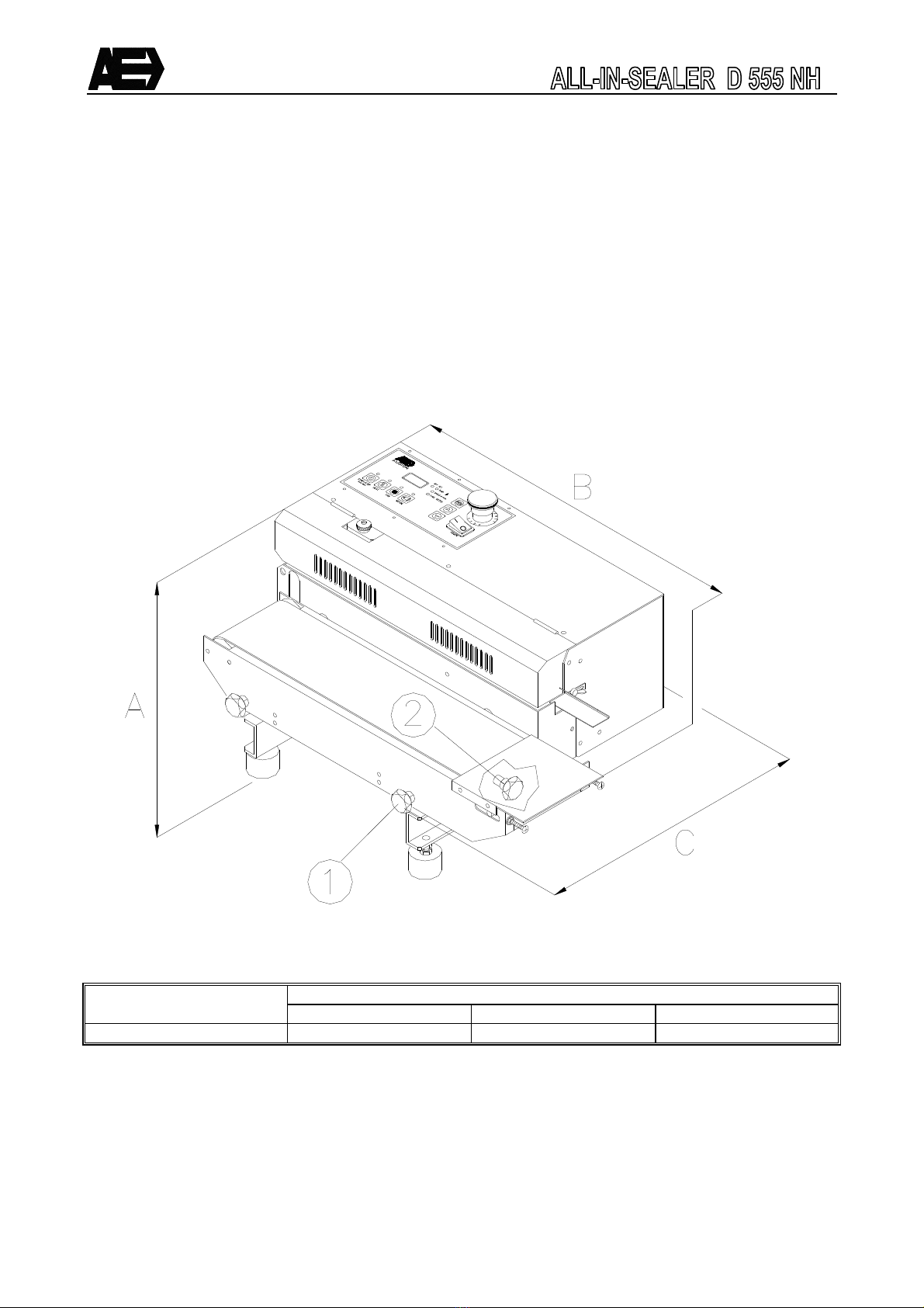
4 imensions
MACHINE Outer dimensions (mm)
A B C
ALL-IN-SEALER D 555 NH
270 610 460
Fig 2

6
5 Operation panel
The operation panel contains:
1 POWER Main switch, turns the power on/off
2 Emergency stop Stops machine immediately in case of emergency
3 START/STOP Button to start/stop the machine If the machine will be stopped and the actual
temperature is above the 80°C The machine will cooldown till 80°C in the cool run
mode After the cool run mode the machine automatically switches off to the standby
mode
4 HEAT Turns the heater on/off
5 FAN Turns the fan on/off
6 MOTOR Turns the motor on/off
7 Leds These leds indicate an active function
8 Display The display shows the temperature/speed/sync factor/cool run/errors
9 Leds During the adjustment these leds indicate which adjustment is active
10 PROG Button to pass the temp/speed/sync adjustments
After 30 seconds from the last button pressure, the program returns automatically to
the actual temperature
11 Down Button to decrease the adjusted value
12 Up Button to increase the adjusted value
Fig 3

7
6 Installation
6.1 Description of workplace
Install the ALL-IN-SEALER in a ventilated, well illuminated space Ensure that the ALL-IN-SEALER is not
exposed to direct sunlight, extreme temperatures, damp, dust or sand The ALL-IN-SEALER is not allowed
to be exposed to mechanical shocks or vibrations
6.2 Connecting ALL-IN-SEALER
Before connecting the ALL-IN-SEALER, be sure that the power is off, the main switch (fig 3 pos 1)
must be at position O (OFF)
6.2.1 Adjusting height transport belt
Adjust the height of the conveyor in relation to the seal unit The bag must be sealed at the half of the
product height
− Loosen the two knobs (fig 2 pos 1)
− Adjust the height of the transport belt by raising or lowering it manually
− If the transport belt is at the correct height, and the transport belt is horizontal, tighten the two knobs
to secure the transport belt
6.2.2 Connecting to power supply
Connect the power cord into the power supply The main socket must have an ground connection
and must be max fused at 16 Ampere

8
6.3 A justing seal temperature/spee
Use the PROG-button to change the adjustments The leds indicates which adjustment is selected After 30
seconds from the last button pressure, the program returns automatically to the actual seal temperature
To find the ideal sealing temperature and speed Make a couple of trial seals with different adjustments The
settings for a good seal are a combination between sealing temperature (TEMP) and on the other side the
operation speed (SPEED)
Adjust the next parameters:
− The sealing temperature to 100°C
− The operation speed “speed” to 50
Follow the next steps to adjust the seal temperature and the operation speed:
− Press on PROG
− Led TEMP/SET illuminates and the display shows the actual adjusted temperature
− Press on UP/DOWN to raise or lower the adjusted temperature
− Press on PROG
− Led SPEED/SET illuminates and the display shows the actual adjusted operation speed
− Press on UP/DOWN to raise or lower the adjusted operation speed
− Press the PROG-button again to return to the actual temperature
The led of the seal temperature TEMP/ACT flashes if the temperature deviation is more than 5 degrees from
the adjusted value
Make a couple of bags Re-adjust if the bags are not sealed properly
− The seals are not tight The sealing temperature is too low and the operation speed too high
− The seals looks melted The sealing temperature is too high and the operation speed too low
6.4 Cool run
Turn off the machine with the START/STOP-button The machine will cool down to 80°C in the cool run
mode After the cool run mode the machine automatically switches off to the standby mode During the cool
run mode the motor and fan turn on and the heater turns off automatically The cool run protects the PTFE-
belts against burning That will increase the life cycle of the belts Below 80°C the cool run turns off the
machine immediately to the standby mode
The START/STOP led flashes during the cool run The display shows intermittent “c-r” and the actual
temperature
6.5 Stan by
Turn the machine off with the cool run After the cool run mode the machine automatically switches off to the
standby mode The display shows “- - -“ and all functions are shut down Press a button to turn the machine
on again If the All-in is not to be used for a long period of time, use the main switch (POWER) to turn off the
machine In this way the current is shut down

9
6.6 Preparation for use
After the All-in is connected to the power and properly checked The machine can be put into operation
− Reset the emergency stop
− Set the main switch (POWER) to on (1)
− Adjust the seal temperature (TEMP)
− Adjust the operation speed (SPEED)
− Turn on the MOTOR, FAN, and HEATER if necessary
− Press START/STOP to turn on the machine
− Let the machine heat up The led TEMP/ACT stops flashing if the machine is at the set temperature
Turn off the All-in normally with the cool run If the All-in is not used for a longer period of time, set the main
switch (POWER) off and disconnect the power cord from the mains supply
6.7 Emergency stop
In case of emergency the emergency stop (fig 4) can be
activated This causes the power supply to be shut off and the
machine to stop
The emergency stop should only be used for emergencies and
not for a temporary switch off or stop of the machine
The emergency stop is operated by means of pushing the red
button (fig 4) on top of the machine After each use of the
emergency stop it should be resetted by turning the red button in
the direction of the arrow
After resetting the emergency stop, press the START/STOP-
button and the machine starts running again
7 Specifications
7.1 Operational specifications
− Operation speed : max 10 meter per minute
− Ambient temperature : +5ø +40ø Celsius
− Humidity : 30% 95% rel (without condensation)
− Fastening, fixing : The ALL-IN-SEALER is standing on 4 rubber feet
− Explosion safety : Not to be used in explosive surroundings
− Extraction, ventilation : To be used in ventilated spaces
7.2 Applocations not allowe
− Packing in medical, sterile environment
− Use in an explosive surrounding
− Packing of poisonous, corrosive, irritating substances
− Packing of explosive materials
− Packing of (dangerous) dusty products
Fig 4

10
8 Maintenance
The ALL-IN-SEALER is a relatively simple machine which needs very little maintenance There are a few
repairs which could be carried out by yourself For other repairs please contact your dealer or Audion
Elektro
− Always dissonnect the sealer from the main power supply in case of maintenance or repairs
− Wait till the machine has cooled down before any maintenance or repairs are carried out
− Before switching off the cooling ventilator and the motor the ALL-IN-SEALER must cool down or at
least 10 minutes!
− Only use spare parts supplied by Audion Elektro
The maintenance schedule below is for normal use In case of intensive use or under extreme
circumstances maintenance should be executed more frequently
Daily maintenance:
PTFE-belts Check if the PTFE-belts are clean If necessary, clean them
with a wet cloth
Heating plates Check if the plates are clean If necessary, clean them with a
wet cloth
Weekly maintenance:
Driving mechanism Check condition of driving mechanism and rotating parts If
needed, lubricate them
V-belts Check condition (rupture) and tension
Conveyor belt Check condition (rupture) and tension
Cleaning Clean the All-In-Sealer with a wet cloth and soft soap

11
8.1 Maintenance an a justing ALL-IN-SEALER
In order to be able to carry out maintenance or to replace spareparts easily you should:
− Disconnect the ALL-IN-SEALE from the power supply
− Loosen the two knobs under the transport belt, and move the transport belt as far as possible from the
ALL-IN-SEALER
− See fig 5 - Remove the back cover (1)
- Open the upper front cover (2)
- Remove the lower front cover (3)
Take care! The heating plates can still be hot Before switching off the cooling ventilator and the
motor, the machine must cool down for at least 10 minutes!!
When all activities have been done, remount the rear cover and the protection covers
DO NOT OPERATE THE MACHINE IF THE PROTECTION COVERS HAVE NOT BEEN MOUNTED
Fig 5

12
8.2 Heating elements
The heating elements are mounted in the heating plates In order to obtain a good seal correct adjustment of
the heating plates is essential Adjustment of the heating plates depends on the material properties
8.2.1 Adjust heating plates
If very thick films need to be sealed, it may be necessary to
adjust the distance between the two heating and cooling
elements If this is the case, then:
− Carry out the activities as described in § 8 1
− Turn the 4 nuts (fig 6 pos 2) clockwise a few times to
raise the elements Counter clockwise to lower the
elements
− Close all covers
8.2.2 Replace heating elements
− Remove the back cover
− Open the upper front cover
− Loosen the 3 screws (fig 6 pos 1) to remove the complete moutingplate
− Disconnect the wiring of the heating elements
− Loosen the cup (fig 6 pos 3) to replace the heating element (fig 6 pos 4)
− Connect the wiring and place the mounting plate
− Mount all covers
8.3 PTFE-belts
The PTFE-belts prevent contact of the product to be sealed with the heating plates The PTFE-belts should
never be folded as otherwise the folded part of the bands becomes a weak point during use
8.3.1 Adjust P FE-belts
Note : Do not adjust the heating plates too tight to prevent unnecessary wear of the PTFE-belts
See § 8 2 1
The PTFE-belts are being tensioned by springs, which means that these belts do not need separate
adjustments
Fig 6

13
8.3.2 Replace P FE-belts
Burnt or worn PTFE-belts can be replaced easily:
− Carry out the activities as described in § 8 2 1
− Remove the V-belts as described in § 8 4 1
− Raise the heating and cooling plates by rotating the handles above the plates clockwise (fig 6 pos 5)
− Push the PTFE pulley on the righthand-side to the left until you hear a click The pulley is now locked
− Place the new PTFE belt over the pulley's
− Press the screw above or below (depending on what pulley you are working on) the guide block to
unlock the pulley
− Lower the heating and cooling plate
− Close the covers as described in § 8 1
14
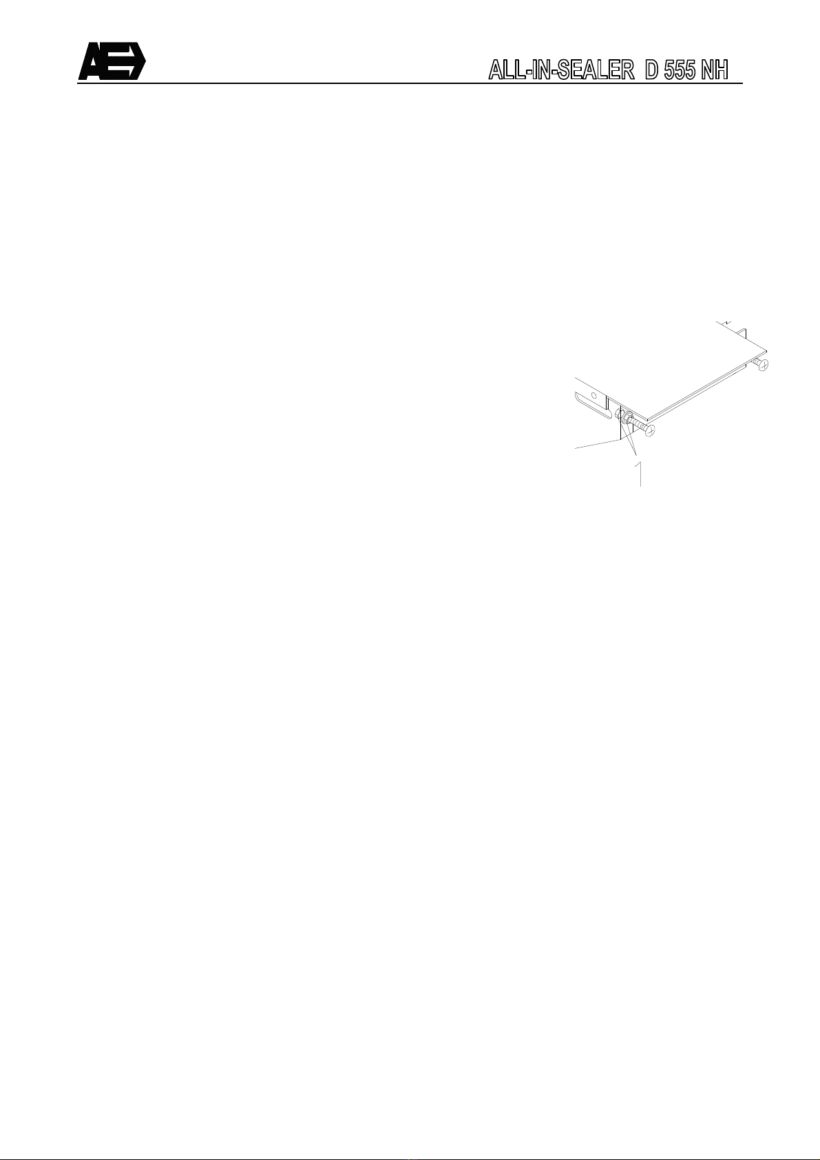
8.4 V-belts
There are 2 V-belts in the ALL-IN-SEALER They are located at the lefthand-side of the machine
8.4.1 Replace v-belts
− Carry out the activities as described in § 8 2 1
− Loosen the nut (fig 7 pos 1) and slide the shaft (pos 2) to the
right
− Replace the v-belt
− Tension the v-belt by sliding the shaft (pos 2) to the left, and
fasten the nut
− Close all covers
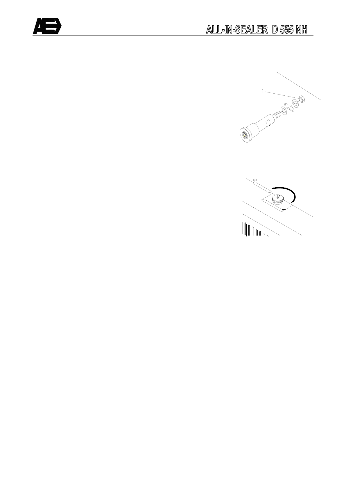
8.5 Pressure roller
The pressure roller applies an extra pressure onto the cooled seal
The pressure roller can be replaced by a code roller
In case the pressure roller is not needed, it can be disabled
By turning the ring (fig 8 pos 1) clockwise the pressure roller is lifted
upwards
Fig 8
Fig 7
15
Fig 9
8.6 Transport belt
The transport belt supports and transports the packing to be sealed The transport belt prevents the packing
from hanging on the seal
Make sure that:
− The distance between the transport belt and the sealunit is correct (half of the thickness of the
packing that is to be sealed
− The transport belt does not run against anything
8.6.1 Adjust transport belt
Adjust the transport belt if:
− the belt touches the sides
− the tension on the belt is too high or too low
Note: Loosen the 4 locknuts (fig 9 pos 1) before adjusting the tension
Only adjust the tension when the belt is running slowly
The tension can be adjusted by rotating the front or rear locknut (fig 9
pos 1):
− Clockwise tension belt
− Counter clockwise release belt
If the transport belt touches one side of the frame;
− Tension the belt on the side it is touching
− Release the belt on the other side
If the transport belt has been incorrectly tensioned;
− Tension the belt equally by adjusting both sides

16
8.7 Motor Set-up
The machine has an automatic motor set-up function This motor set-up function must be carried out when a
motor is replaced During this set-up the motor will run at full speed for a few seconds Be aware that the
machine can run safely for a few seconds
To perform a motor set-up follow the next steps:
− Select the ‘SPEED’ mode with the ‘PROG’ button
− Press the ‘PROG’ button for 5 seconds till ‘SP1’ appears in the display
− Start the set-up routine by pressing the ‘PROG’ button The motor will run at maximum speed for a
few seconds
− End the function by pressing the ‘PROG’ button for 5 seconds till the SPEED settings appear on the
display
8.8 Correction factor
The machine has correction factors to adjust the motor if necessary This factor (%) will affect the motor
output If set at e g 90 the motor will run slower and set at e g 110 the motor will run faster
To perform a motor set-up follow the next steps:
− Select the ‘SPEED’ mode with the ‘PROG’ button
− Press the ‘MOTOR’ and ‘PROG’ button simultaneous for 5 seconds till ‘CF1’ appears in the display
− Set the CF1 setting with the ‘UP’ or ‘DOWN’ button
− End the function by pressing the ‘PROG’ button for 5 seconds till the SPEED settings appear on the
display
8.9 Reset to factory settings
The machine has a function to reset all settings to the original factory settings
Note that if you reset the machine all settings prior made will be lost
To perform a reset follow the next steps:
− Switch the main power OFF
− Keep the ‘START/STOP’ button pressed, while the main power is switched ON, until ‘rES’ appears in
the display
− Perform a motor set-up (see 8 7)
− Adjust the correction factor if necessary (see 8 8)

17
8.10 Print jumpers
There are two jumpers on the back of the PCB These two jumpers will adjust:
Jumper 1: Voltage 240V-50Hz / 115V-60Hz
Jumper 2: No application
The display shows the current jumper adjustment Turn the All-in on by the main switch (POWER) The first
two seconds, the display shows the software version and the jumper configuration
Code in display Jumper 1 Jumper 2
J 1 2 50Hz No application
J - 2 60Hz No application
J 1 - 50Hz No application
J - - 60Hz No application
The jumpers of the PCB are placed on the right side in the middle
The standard values are ON and 50Hz if the jumpers are removed
9 Technical data
ALL-IN-SEALER D 555 NH
Dimensions
Weight
Sealwidth
Power rating
Voltage
Frequency
Noise
See §4
29 kg
10 mm
550 Watt
230 V
50 Hz
≤ 70 dB(A)
10 Problems and solutions
Problem Cause Solution
The All-in sealer does not work - Main switch is at “0”
- The plug is not properly in the
main power supply
- Emergency stop has been
activated
- Internal interruption
- Set the main switch to “1”
(fig 3 pos 1)
- Insert the plug properly into
the main power supply
- Unlock the emergency stop
¤ 6 7
- Contact your dealer or
Audion Elektro B V
The All-in makes a bad seal - Temperature has not been
set well
- Set the temperature ¤ 6 3
Fig 10

18
- Speed has not been set well
- Heating plates and/or PTFE-
belts are dirty
- Seal is not well cooled
- PTFE-belts are worn
- Adjust the speed ¤ 6 3
- Clean the heating plates
and/or PTFE-belts
- Switch on the cooling
- Replace the PTFE-belts
Cooling does not work - The fan is turned off
- Internal interruption
- Switch on the fan
- Contact your dealer or
Audion Elektro B V
Error codes in display E1
E2
E3
- Wrong frequency 50/60Hz
- Loose wire to PT100
- Short circuit in PT100
- Check the frequency and
adjust the jumper
- Check wiring and connections
to the PT100
- Replace PT100
Conveyor does not work - Speed is at 0
- Internal interruption
- Adjust the speed ¤ 6 3
- Contact your dealer or
Audion Elektro B V
11 Recommended spare parts
A TICLE NUMBE
NAME
PE MACHINE
305-02002 V-belt 2
129-02003 PTFE belt 2
129-03000 Heating element 2
FUSE PCB
NAME
PE MACHINE
052026 Fuse F1 125mAT 1
160-1343125 Fuse F2 10AT 1
052010 Fuse F3 2AT 1
160-1343127 fuse F4 500mAT 1

19
12 iscard the All-in
In accordance with the directive 2002/96/CE, the logo below indicates that the equipment concerned is not
to be disposed of as ordinary waste at the end of its useable life
The equipment is to be delivered to a suitable depot that will dispose of the equipment in a proper way in
accordance with the legislation on this subject, or to the supplier of new equipment in case of replacement
The owner of the equipment is responsible for proper disposal of the equipment
For further information we advise you to contact your local waste facility
Appropriate disposal of Waste of Electric and Electronic Equipment prevents unnecessary pollution
of the environment and negative influence on general health.
13 Conditions of guarantee
13.1 Liability
1 We exclude any liability as far as it has not been arranged by law
2 Our liability will never exceed the amount of order
3 Subject to the general valid regulations of the law, we are not obliged to any compensation of
damage of which kind ever, directly or indirectly, under which company damage, to movables and
immovables or to persons, both to the opposite party as to third persons
4 In no way we are liable for damage arisen from or caused by the supplied or by the
unsuitability of this for the purpose for which the opposite party has purchased the
machine
13.2 Guarantee
1 With due observance of the restrictions stated hereafter, we allow 12 months of guarantee to the
products supplied by us This guarantee is restricted to the occurring manufacture errors and does
not imply interruptions caused by any form of wear spare parts subject to use
2 To spare parts or enclosures obtained from third persons we do not give longer guarantee than this
third supplier does
3 Guarantee expires if the opposite party and/or third parties associated make improper use of the
supplied
4 Guarantee also expires if the opposite party and/or third parties associated execute activities and/or
modifications to the supplied
5 In case we replace spare parts to fulfill our guarantee engagement, the spare parts replaced
become property of AUDION ELEKTRO B V
6 In case the opposite party does not come up completely, partially or does not come up in time to the
obligations arisen from the closed engagement between the parties, we are not obliged to guarantee
as long as the situation continues

Appendix A1
14 Electrical circuit
Table of contents
Other Audion Elektro Food Saver manuals

Audion Elektro
Audion Elektro Sealmaster Magneta 421 MGI User manual

Audion Elektro
Audion Elektro 255 PR User manual

Audion Elektro
Audion Elektro SEALBOY SB 236 User manual

Audion Elektro
Audion Elektro D 555 NVT User manual

Audion Elektro
Audion Elektro Sealmaster MAGNETA MG 321 User manual

Audion Elektro
Audion Elektro MAGNETA MGMI 421 User manual

Audion Elektro
Audion Elektro SUPER CELLO 300 SC User manual

Audion Elektro
Audion Elektro Futura Portable 150 B User manual

Audion Elektro
Audion Elektro SEALBOY SB 321 User manual

Audion Elektro
Audion Elektro Sealmaster Magneta 421 MGI User manual


