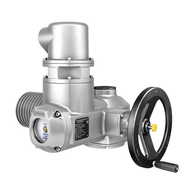
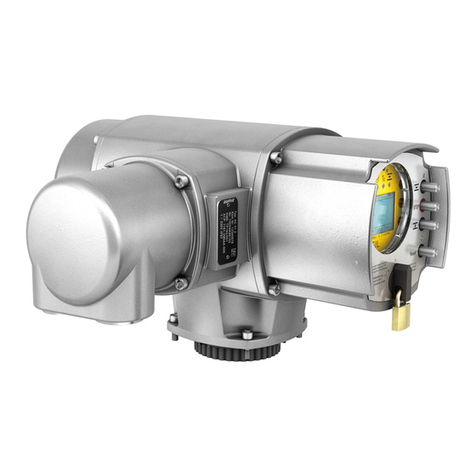
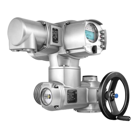
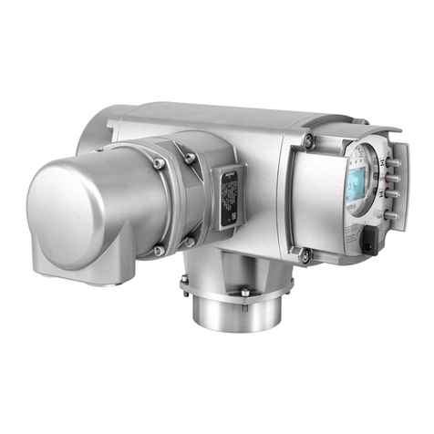
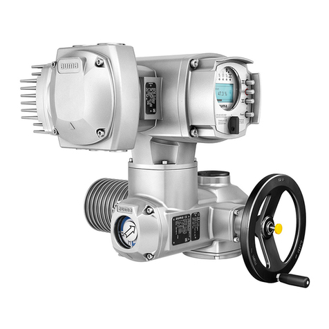
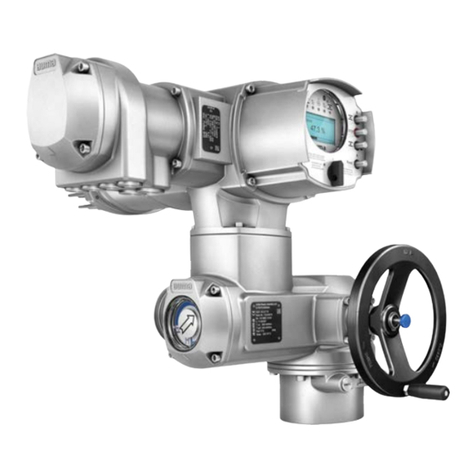
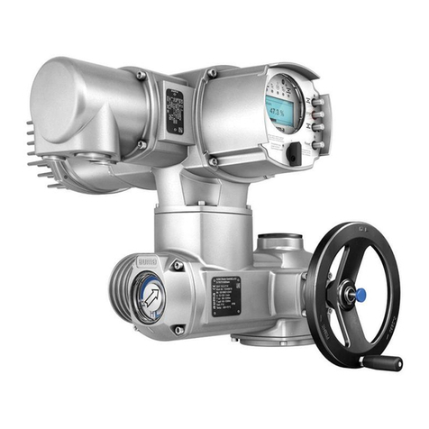
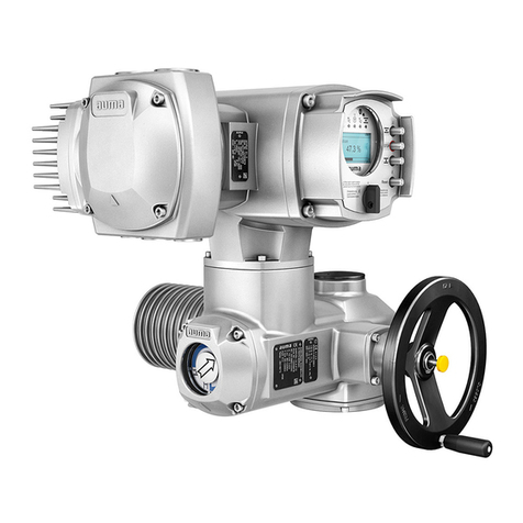
AUMA SQ 05.2 User manual

Part-turn actuators
SQ 05.2 –SQ 14.2
SQR 05.2 –SQR 14.2
AUMA NORM (without controls)
Assembly, operation, commissioningOperation instructions

Read operation instructions first.
●Observe safety instructions.
●These operation instructions are part of the product.
●Retain operation instructions during product life.
●Pass on instructions to any subsequent user or owner of the product.
Purpose of the document:
This document contains information for installation, commissioning, operation and maintenance staff.It is intended
to support device installation and commissioning.
Table of contents Page
41. Safety instructions................................................................................................................. 41.1. Basic information on safety 41.2. Range of application 51.3. Applications in Ex zone 22 (option) 51.4. Warnings and notes 61.5. References and symbols
72. Identification........................................................................................................................... 72.1. Name plate 92.2. Short description
103. Transport, storage and packaging........................................................................................ 103.1. Transport 113.2. Storage 113.3. Packaging
124. Assembly................................................................................................................................ 124.1. Mounting position 124.2. Handwheel fitting 124.3. Part-turn actuator to valve: mount 134.3.1. Output drive for coupling 134.3.1.1. Part-turn actuator (with coupling): mount to valve
165. Electrical connection............................................................................................................. 165.1. Basic information 175.2. S/SH electrical connection (AUMA plug/socket connector) 185.2.1. Terminal compartment : open 195.2.2. Cable connection 215.2.3. Terminal compartment : close 225.3. Accessories for electrical connection 225.3.1. Parking frame 225.3.2. DS intermediate frame for double sealing 235.3.3. External earth connection
246. Operation................................................................................................................................ 246.1. Manual operation 246.1.1. Engage manual operation 246.1.2. Manual operation: disengage 246.2. Motor operation
2
SQ 05.2 –SQ 14.2/SQR 05.2 –SQR 14.2
Table of contents

257. Indications.............................................................................................................................. 257.1. Mechanical position indication/running indication via indicator mark on cover
268. Signals (output signals)......................................................................................................... 268.1. Feedback signals from actuator
279. Commissioning (basic settings)........................................................................................... 279.1. End stops in part-turn actuator 289.1.1. End stop CLOSED: set 289.1.2. End stop OPEN: set 289.2. Switch compartment: open 299.3. Torque switching: set 309.4. Limit switching: set 309.4.1. End position CLOSED (black section): set 309.4.2. End position OPEN (white section): set 319.5. Test run 319.5.1. Direction of rotation: check 319.5.2. Limit switching: check 329.6. Mechanical position indicator: set 329.7. Switch compartment: close
3410. Commissioning (optional equipment settings)................................................................... 3410.1. Potentiometer 3410.1.1. Potentiometer: set 3410.2. RWG electronic position transmitter 3510.2.1. Measuring range: set 3510.3. EWG 01.1 electronic position transmitter 3610.3.1. Measuring range: set 3710.3.2. Current values : adjust 3810.3.3. LED end position signalling: switch on/off 3810.4. Intermediate positions: set 3910.4.1. Running direction CLOSE (black section): set 3910.4.2. Running direction OPEN (white section): set
4011. Corrective action.................................................................................................................... 4011.1. Faults during commissioning 4011.2. Motor protection (thermal monitoring)
4212. Servicing and maintenance................................................................................................... 4212.1. Preventive measures for servicing and safe operation 4212.2. Maintenance 4212.3. Disposal and recycling
4413. Technical data......................................................................................................................... 4413.1. Technical data Part-turn actuator
4714. Spare parts............................................................................................................................. 4714.1. Part-turn actuators SQ 05.2 –SQ 14.2/SQR 05.2 –SQR 14.2
4915. Certificates.............................................................................................................................. 4915.1. Declaration of Incorporation and EC Declaration of Conformity
52Index........................................................................................................................................
54Addresses...............................................................................................................................
3
SQ 05.2 –SQ 14.2/SQR 05.2 –SQR 14.2 Table of contents

1. Safety instructions
1.1. Basic information on safety
Standards/directives Our products are designed and manufactured in compliance with recognised
standards and directives.This is certified in a Declaration of Incorporation and an
EU Declaration of Conformity.
The end user or the contractor must ensure that all legal requirements, directives,
guidelines, national regulations and recommendations with respect to assembly,
electrical connection, commissioning and operation are met at the place of installation.
Safetyinstructions/warn-
ings All personnel working with this device must be familiar with the safety and warning
instructions in this manual and observe the instructions given. Safety instructions
and warning signs on the device must be observed to avoid personal injury or property
damage.
Qualification of staff Assembly, electrical connection, commissioning, operation, and maintenance must
be carried out by suitably qualified personnel authorised by the end user or contractor
of the plant only.
Prior to working on this product, the staff must have thoroughly read and understood
these instructions and, furthermore, know and observe officially recognised rules
regarding occupational health and safety.
Commissioning Prior to commissioning, it is important to check that all settings meet the requirements
of the application. Incorrect settings might present a danger to the application, e.g.
cause damage to the valve or the installation.The manufacturer will not be held
liable for any consequential damage.Such risk lies entirely with the user.
Operation Prerequisites for safe and smooth operation:
●Correct transport, proper storage, mounting and installation, as well as careful
commissioning.
●Only operate the device if it is in perfect condition while observing these instruc-
tions.
●Immediately report any faults and damage and allow for corrective measures.
●Observe recognised rules for occupational health and safety.
●Observe national regulations.
●During operation,the housing warms upandsurfacetemperatures >60°C may
occur.To prevent possible burns, we recommend checking the surface temper-
ature using an appropriate thermometer and wearing protective gloves, if re-
quired, prior to working on the device.
Protective measures The end user or the contractor are responsible for implementing required protective
measures on site, such as enclosures, barriers, or personal protective equipment
for the staff.
Maintenance To ensure safe device operation, the maintenance instructions included in this manual
must be observed.
Any device modification requires prior written consent of the manufacturer.
1.2. Range of application
AUMA part-turn actuators are designed for the operation of industrial valves, e.g.
butterfly valves and ball valves.
Other applications require explicit (written) confirmation by the manufacturer.
The following applications are not permitted, e.g.:
●Industrial trucks according to EN ISO 3691
●Lifting appliances according to EN 14502
●Passenger lifts according to DIN 15306 and 15309
●Service lifts according to EN 81-1/A1
4
SQ 05.2 –SQ 14.2/SQR 05.2 –SQR 14.2
Safety instructions

●Escalators
●Continuous duty
●Buried service
●Continuous submersion (observe enclosure protection)
●Potentially explosive areas, with the exception of zone 22
●Radiation exposed areas in nuclear power plants
No liability can be assumed for inappropriate or unintended use.
Observance of these operation instructions is considered as part of the device's
designated use.
Information These operation instructions are only valid for the "clockwise closing" standard
version, i.e. driven shaft turns clockwise to close the valve.
1.3. Applications in Ex zone 22 (option)
Actuators of the indicated series basically meet the requirements for applications in
dust hazardous locations of ZONE 22 in compliance with the ATEX directive
2014/34/EU.
To comply with all requirements of the ATEX directive, observe the following points:
●Actuators are marked with the explosion protection designation II3D... for use
in ZONE 22.
●Maximum surface temperature of actuators
- T150 °C for ambient temperatures up to +60 °C or
- T190 °C for ambient temperatures up to +80 °C.
Increased dust deposit on the equipment was not considered for the determin-
ation of the maximum surface temperature.
●The following conditions must be fulfilled to respect the maximum permissible
surface temperatures at the actuator:
- Respecting types of duty and technical manufacturer data
- Correct connection of thermal motor protection (thermoswitches or PTC
thermistor)
Maximum
surface temperature
Tripping temperature
Thermal motor protection
Ambient temperature
T150 °C140 °Cup to +60 °C T190 °C155 °Cup to +80 °C
●The connector may only be connected or disconnected when not live.
●The cable glands and cable entries used have to meet the requirements of
category II3D and must at least comply with enclosure protection IP67.
●The actuators must be connected by means of an external earth connection
(accessory part) to the equipotential earth bonding or integrated into an earthed
piping system.
●As a general rule, the requirements of IEC 60079 Parts 14 and 17 must be re-
spected in dust hazardous locations.During commissioning, service, and
maintenance, special care as well as qualified and trained personnel are required
for safe actuator operation.
1.4. Warnings and notes
The following warnings draw special attention to safety-relevant procedures in these
operation instructions, each marked by the appropriate signal word (DANGER,
WARNING, CAUTION, NOTICE).
Indicates an imminently hazardous situation with a high level of risk. Failure
to observe this warning could result in death or serious injury.
5
SQ 05.2 –SQ 14.2/SQR 05.2 –SQR 14.2 Safety instructions

Indicates a potentially hazardous situation with a medium level of risk.Failure
to observe this warning could result in death or serious injury.
Indicates a potentially hazardous situation with a low level of risk. Failure to
observe this warning may result in minor or moderate injury. May also be used
with property damage.
Potentially hazardous situation. Failure to observe this warning may result in
property damage. Is not used for personal injury.
Arrangement and typographic structure of the warnings
Type of hazard and respective source!
Potential consequence(s) in case of non-observance (option)
→Measures to avoid the danger
→Further measure(s)
Safety alert symbol warns of a potential personal injury hazard.
The signal word (here: DANGER) indicates the level of hazard.
1.5. References and symbols
The following references and symbols are used in these instructions:
Information The term Information preceding the text indicates important notes and information.
Symbol for CLOSED (valve closed)
Symbol for OPEN (valve open)
Important information before the next step.This symbol indicates what is required
for the next step or what has to be prepared or observed.
< > Reference to other sections
Terms in brackets shown above refer to other sections of the document which provide
further information on this topic.These terms are either listed in the index, a heading
or in the table of contents and may easily be located.
6
SQ 05.2 –SQ 14.2/SQR 05.2 –SQR 14.2
Safety instructions

2. Identification
2.1. Name plate
Figure 1: Arrangement of name plates
[1] Motor name plate
[2] Actuator name plate
[3] Additional plate, e.g. KKS plate (Power Plant Classification System)
Actuator name plate
Figure 2: Actuator name plate (example)
(= manufacturer logo); (= CE mark)
[1] Name of manufacturer
[2] Address of manufacturer
[3] Type designation
[4] Order number
[5] Serial number
[6] Operating time in [s] for a part-turn movement of 90°
[7] Torque range in direction CLOSE
[8] Torque range in direction OPEN
[9] Type of lubricant
[10] Permissible ambient temperature
[11] Can be assigned as an option upon customer request
[12] Enclosure protection
[13] Data Matrix code
7
SQ 05.2 –SQ 14.2/SQR 05.2 –SQR 14.2 Identification

Motor name plate
Figure 3: Motor name plate (example)
(= manufacturer logo); (= CE mark)
[1] Motor type
[2] Motor article number
[3] Serial number
[4] Current type, mains voltage
[5] Rated power
[6] Rated current
[7] Type of duty
[8] Enclosure protection
[9] Motor protection (temperature protection)
[10] Insulation class
[11] Output speed
[12] Power factor cos phi
[13] Mains frequency
[14] Data Matrix code
Descriptions referring to name plate indications
Type designation Figure 4:Type designation (example)
1. Type and size of actuator
2. Flange size
Type and size
These instructions apply to the following devices types and sizes:
●Type SQ = Part-turn actuators for open-close duty
Sizes: 05.2, 07.2, 10.2, 12.2, 14.2
●Type SQR= Part-turn actuators for modulating duty
Sizes: 05.2, 07.2, 10.2, 12.2, 14.2
Order number The product can be identified using this number and the technical data as well as
order-related data pertaining to the device can be requested.
Please always state this number for any product inquiries.
On the Internet at http://www.auma.com > Service & Support >myAUMA, we offer
a service allowing authorised users to download order-related documents such as
wiring diagramsand technical data (bothinGerman and English),inspectioncertificate
and the operation instructions when entering the order number.
8
SQ 05.2 –SQ 14.2/SQR 05.2 –SQR 14.2
Identification

Actuator serial number Table 1:
Description of the serial number (with example 0516NS12345)
NS123451605 Positions 1+2: Assembly in week = week 0505 Positions 3+4:Year of manufacture = 201616 Internal number for unambiguous product identificationNS12345
Data Matrix code When registered as authorised user, you may use the AUMA Support App to scan
the Data Matrix code and directly access the order-related product documents without
having to enter order number or serial number.
Figure 5: Link to the App store:
2.2. Short description
Part-turn actuator Definition in compliance with EN 15714-2/EN ISO 5211:
A part-turn actuator is an actuator which transmits a torque to the valve for less than
one full revolution. It need not be capable of withstanding thrust.
AUMA part-turn actuators SQ 05.2 –SQ 14.2/SQR 05.2 –SQR 14.2 are driven by
an electric motor. For manual operation, a handwheel is provided. Switching off in
end positions may be either by limit or torque seating.Actuator controls are required
to operate or process the actuator signals.
Actuators without controls can be equipped with AUMA actuator controls at a later
date.For more information, please state our order number (refer to actuator name
plate).
9
SQ 05.2 –SQ 14.2/SQR 05.2 –SQR 14.2 Identification

3. Transport, storage and packaging
3.1. Transport
For transport to place of installation, use sturdy packaging.
Hovering load!
Risk of death or serious injury.
→Do NOT stand below hovering load.
→Attach ropes or hooks for the purpose of lifting by hoist only to housing and NOT
to handwheel.
→Actuators mounted on valves: Attach ropes or hooks for the purpose of lifting
by hoist to valve and NOT to actuator.
→Actuatorsmountedto gearboxes:Attach ropesorhooks forthe purposeoflifting
by hoist only to the gearbox using eyebolts and NOT to the actuator.
→Respect total weight of combination (actuator, gearbox, valve)
→Secure load against falling down, sliding or tilting.
→Perform lift trial at low height and eliminate any potential danger e.g.by tilting.
Figure 6: Example: Lifting the actuator
Table 2:
Dimensions Part-turn actuators SQ 05.2 –SQ 14.2 / SQR 05.2 –SQR 14.2
with 3-phase AC motors Weight with base and lever2)
Weight1)
Type designation
Actuator approx. [kg]approx. [kg] 2721SQ 05.2/
SQR 05.2 2721SQ 07.2/
SQR 07.2 3126SQ 10.2/
SQR 10.2 4335SQ 12.2/
SQR 12.2 5544SQ 14.2/
SQR 14.2
Indicated weight includes AUMA NORM part-turn actuator with 3-phase AC motor, electrical con-
nection in standard version, unbored coupling and handwheel.For other output drive types, heed
additional weights.
1)
lndicated weight includes AUMA NORM part-turn actuator with 3-phase AC motor, electrical connec-
tion in standard version, and handwheel, including base and lever. For other output drive types,
heed additional weights.
2)
10
SQ 05.2 –SQ 14.2/SQR 05.2 –SQR 14.2
Transport, storage and packaging

Table 3:
Dimensions Part-turn actuators SQ 05.2 –SQ 14.2 / SQR 05.2 –SQR 14.2
with 1-phase AC motors Weight with base and lever2)
Weight 1)
Type designation
Actuator approx. [kg]approx. [kg] 2923SQ 05.2/
SQR 05.2 2923SQ 07.2/
SQR 07.2 3228SQ 10.2/
SQR 10.2 4537SQ 12.2/
SQR 12.2 5746SQ 14.2/
SQR 14.2
Indicated weight includes AUMA NORM part-turn actuator with 1-phase AC motor, electrical con-
nection in standard version, unbored coupling and handwheel.For other output drive types, heed
additional weights.
1)
Indicated weight includes AUMA NORM part-turn actuator with 1-phase AC motor, electrical con-
nection in standard version, and handwheel, including base and lever. For other output drive types,
heed additional weights.
2)
3.2. Storage
Danger of corrosion due to inappropriate storage!
→Store in a well-ventilated, dry room.
→Protect against floor dampness by storage on a shelf or on a wooden pallet.
→Cover to protect against dust and dirt.
→Apply suitable corrosion protection agent to uncoated surfaces.
Long-term storage For long-term storage (more than 6 months), observe the following points:
1. Prior to storage:
Protect uncoated surfaces, in particular the output drive parts and mounting
surface, with long-term corrosion protection agent.
2. At an interval of approx. 6 months:
Check for corrosion.If first signs of corrosion show, apply new corrosion protec-
tion.
3.3. Packaging
Our products are protected by special packaging for transport when leaving the
factory.The packaging consists of environmentally friendly materials which can easily
be separated and recycled.We use the following packaging materials: wood,
cardboard, paper, and PE foil.For the disposal of the packaging material, we
recommend recycling and collection centres.
11
SQ 05.2 –SQ 14.2/SQR 05.2 –SQR 14.2 Transport, storage and packaging

4. Assembly
4.1. Mounting position
The product described in this document can be operated without restriction in any
mounting position.
4.2. Handwheel fitting
Figure 7: Handwheel
[1] Spacer
[2] Input shaft
[3] Handwheel
[4] Retaining ring
1. If required, fit spacer [1] onto input shaft [2].
2. Slip handwheel [3] onto input shaft.
3. Secure handwheel [3] using the retaining ring [4] supplied.
4.3. Part-turn actuator to valve: mount
Danger of corrosion due to damage to paint finish and condensation!
→Touch up damage to paint finish after work on the device.
→After mounting, connect the device immediately to electrical mains to ensure
that heater minimises condensation.
The part-turn actuator is mounted to the valve using a coupling (standard) or via
lever. Separate instructions are available for actuator mounting to the valve when
equipped with base and lever.
12
SQ 05.2 –SQ 14.2/SQR 05.2 –SQR 14.2
Assembly

4.3.1. Output drive for coupling
Design Figure 8:Valve attachment via coupling
[1] Actuator worm wheel with internal splines
[2] Splined plug-in coupling
[3] Valve shaft (example with key)
Application ●For valve attachments according to EN ISO 5211
●For rotating, non-rising valve stem
4.3.1.1. Part-turn actuator (with coupling): mount to valve
Unbored couplings or couplings with pilot bore must be machined to match the valve
shaft prior to mounting the part-turn actuator to the valve (e.g.with bore and keyway,
two-flat or square bore).
Information Assemble valve and part-turn actuator in the same end position. As standard, the
part-turn actuator is supplied in end position CLOSED.
●Recommended mounting position for butterfly valves:End position CLOSED.
●Recommended mounting position for ball valves:End position OPEN.
Assembly steps 1. If required, move part-turn actuator in same end position as valve using the
handwheel.
2. Clean mounting faces, thoroughly degrease uncoated mounting surfaces.
3. Apply a small quantity of grease to the valve shaft [2].
13
SQ 05.2 –SQ 14.2/SQR 05.2 –SQR 14.2 Assembly

4. Place coupling [1] onto valve shaft [2] and secure against axial slipping by using
a grub screw [3] or a clamping washer and a screw with curved spring lock
washer [4].Thereby, ensure that dimensions X,Y or L are observed (refer to
figure and table <Mounting positions for coupling>).
Figure 9: Examples: Fit coupling
[1] Coupling
[2] Valve shaft
[3] Grub screw
[4] Clamping washer and screw with curved spring lock washer
Figure 10: Mounting positions for coupling
Table 4: SQ 14.2SQ 12.2SQ 10.2SQ 07.2SQ 05.2Dimensions [mm] F6F14F14F12F12F10F10F07F05F07F05EN ISO 5211 88554433333X max. 101010105522222Y max. 125751016182506640404040L max.
5. Apply non-acidic grease at splines of coupling (e.g.Gleitmo by Fuchs).
14
SQ 05.2 –SQ 14.2/SQR 05.2 –SQR 14.2
Assembly

6. Fit part-turn actuator. If required, slightly turn part-turn actuator until splines of
coupling engage.
Figure 11:
Information Ensure that the spigot (if provided) fits uniformly in the recess and that the flanges
are in complete contact.
7. If flange bores do not match thread:
7.1 Slightly rotate handwheel until bores line up.
7.2 If required, shift part-turn actuator by one tooth on the coupling.
8. Fasten part-turn actuator with screws.
Information: We recommend applying liquid thread sealing material to the
screws to avoid contact corrosion.
9. Fasten screws crosswise to a torque according to table.
Table 5:
Tightening torques for screws Tightening torque [Nm]Threads Strength class A2-80/A4–80
10M6 24M8 48M10 82M12 200M16 392M20
15
SQ 05.2 –SQ 14.2/SQR 05.2 –SQR 14.2 Assembly

5. Electrical connection
5.1. Basic information
Danger due to incorrect electrical connection
Failure to observe this warning can result in death, serious injury, or property damage.
→The electrical connection must be carried out exclusively by suitably qualified
personnel.
→Prior to connection, observe basic information contained in this chapter.
→After connection but prior to applying the voltage, observe the <Commissioning>
and <Test run> chapters.
Wiring diagram/terminal
plan The pertaining wiring diagram/terminal plan (in German or English) is attached to
the device in a weather-proof bag, together with these operation instructions.It can
also be requested from AUMA (state order number, refer to name plate) or
downloaded directly from the Internet (http://www.auma.com).
Valve damage for connection without controls!
→NORM actuators require controls: Connect motor via controls only (reversing
contactor circuit).
→Observe the type of seating specified by the valve manufacturer.
→Observe wiring diagram.
Delay time Thedelaytimeis the time from thetripping ofthelimitor torque switchesto the motor
power being switched off.To protect the valve and the actuator, we recommend a
delay time < 50 ms.Longer delay times are possible provided the operating time,
output drive type, valve type, and the type of installation are considered.We
recommend switching off the corresponding contactor directly by limit or torque
switch.
Limit and torque
switches Limit and torque switches can be provided as single, tandem, or triple switches.Only
the same potential can be switched on the two circuits (NC/NO contact) of each
single switch. If different potentials are to be switched simultaneously, tandem
switches or triple switches are required.When using tandem/triple switches:
●For signalling use the leading contacts TSC1, TSO1, LSC1, LSO1.
●For switching off use the lagging contacts TSC,TSO, LSC, LSO.
Current type, mains
voltage, mains fre-
quency
Type of current, mains voltage and mains frequency must match the data on the
motor name plate.Also refer to chapter <Identification>/<Name plate>.
Figure 12: Motor name plate (example)
[1] Type of current
[2] Mains voltage
[3] Mains frequency (for 3-phase and 1-phase AC motors)
Protection and sizing on
site For short-circuit protection and for disconnecting the actuator from the mains, fuses
and disconnect switches have to be provided by the customer.
16
SQ 05.2 –SQ 14.2/SQR 05.2 –SQR 14.2
Electrical connection

The current value for sizing the protection is derived from the current consumption
of the motor (refer to motor name plate).
We recommend adapting the switchgear sizing to the max.current (Imax) and selecting
and setting the overcurrent protection device in compliance with the indications in
the electrical data sheet.
Safety standards Safety measures and safety equipment must comply with the respectively valid
national on site specifications.All externally connected devices shall comply with
the relevant safety standards for the place of installation.
Connecting cables ●We recommend using connecting cables and connecting terminals according
to rated current (IN) (refer to motor name plate or electrical data sheet).
●For device insulation, appropriate (voltage-proof) cables must be used.Specify
cables for the highest occurring rated voltage.
●Use connecting cable with appropriate minimum rated temperature.
●For connecting cables exposed to UV radiation (outdoor installation), use UV
resistant cables.
●For the connection of position transmitters, screened cables must be used.
5.2. S/SH electrical connection (AUMA plug/socket connector)
Figure 13: S and SH electrical connection
[1] Cover
[2] Socket carrier with screw-type terminals
With crimp-type connection as an option
[3] Actuator housing with pin carrier
Short description Plug-in electrical connection with screw-type terminals for power and control contacts.
Control contacts also available as crimp-type connection as an option.
17
SQ 05.2 –SQ 14.2/SQR 05.2 –SQR 14.2 Electrical connection

S version (standard) with three cable entries.SH version (enlarged) with additional
cable entries.For cable connection, remove the AUMA plug/socket connector and
the socket carrier from cover.
Technical data Table 6:
Electrical connection via AUMA plug/socket connector Control contactsPower contacts 50 pins/sockets6 (3 equipped) + protective
earth conductor (PE)
No. of contacts max.
1 to 50U1,V1, W1, U2,V2, W2, PEDesignation 250 V750 VConnection voltage max. 16 A25 ARated current max. Screw connection, crimp-type (option)Screw connectionType of customer connection 2.5 mm2
(flexible or solid)
6 mm2(flexible)
10 mm2(solid)
Connection diameter max.
5.2.1. Terminal compartment : open
Figure 14: Open terminal compartment
[1] Cover (figure shows S version )
[2] Screws for cover
[3] O-ring
[4] Screws for socket carrier
[5] Socket carrier
[6] Cable entry
[7] Blanking plugs
[8] Cable gland (not included in delivery)
Hazardous voltage!
Risk of electric shock.
→Disconnect device from the mains before opening.
1. Loosen screws [2] and remove cover [1].
2. Loosen screws [4] and remove socket carrier [5] from cover [1].
18
SQ 05.2 –SQ 14.2/SQR 05.2 –SQR 14.2
Electrical connection

3. Insert cable glands [8] suitable for connecting cables.
➥The enclosure protection IP…stated on the name plate is only ensured if suit-
able cable glands are used.
Figure 15: Example: Name plate for enclosure protection IP68
4. Seal unused cable entries [6] with suitable blanking plugs [7].
5.2.2. Cable connection
Table 7:
Terminal cross sections and terminal tightening torques Tightening torquesTerminal cross sectionsDesignation 1.2 –1.5 Nm1.0 –6 mm2(flexible)
1.5 –10 mm2(solid)
Power contacts
(U1, V1, W1, U2, V2, W2) 1.2 –2.2 Nm1.0 –6 mm2(flexible) with ring lugs
1.5 –10 mm2(solid) with loops
Protective earth connection (PE)
0.5 –0.7 Nm0.25 –2.5 mm2(flexible)
0.34 –2.5 mm2(solid)
Control contacts
(1 to 50)
Danger of motor damage if PTC thermistors or thermoswitches are not con-
nected!
Our warranty for the motor will lapse if the motor protection is not connected.
→Connect PTC thermistors or thermoswitches to external controls.
1. Remove cable sheathing.
2. Insert the wires into the cable glands.
3. Fasten cable glands with the specified torque to ensure required enclosure
protection.
4. Strip wires.
→Controls approx. 6 mm, motor approx. 10 mm
5. For flexible cables:Use wire end sleeves according to DIN 46228.
6. Connect cables according to order-related wiring diagram.
19
SQ 05.2 –SQ 14.2/SQR 05.2 –SQR 14.2 Electrical connection

In case of a fault: Hazardous voltage while protective earth conductor is NOT
connected!
Risk of electric shock.
→Connect all protective earth conductors.
→Connect PE connection to external protective earth conductor of connecting
cables.
→Start running the device only after having connected the protective earth con-
ductor.
7. Tighten PE conductors firmly to PE connection using ring lugs (flexible cables)
or loops (solid cables).
Figure 16: Protective earthing
[1] Socket carrier
[2] Screw
[3] Washer
[4] Lock washer
[5] Protective earth with ring lugs/loops
[6] Protective earthing, symbol:
8. Forshieldedcables:Link thecableshieldend via the cablegland tothehousing
(earthing).
20
SQ 05.2 –SQ 14.2/SQR 05.2 –SQR 14.2
Electrical connection
Other manuals for SQ 05.2
5
This manual suits for next models
9
Table of contents
Other AUMA Controllers manuals

AUMA
AUMA SA 48.1 SAR 25.1 User manual

AUMA
AUMA SAEx Series User manual

AUMA
AUMA SGM 04.1 User manual

AUMA
AUMA SA 16.1 User manual

AUMA
AUMA SAE 07.2 Series Training manual

AUMA
AUMA SBA 12 User manual

AUMA
AUMA SG 05.1-F05 User manual

AUMA
AUMA PROFOX PF-Q80 User manual

AUMA
AUMA SG 05.1 User manual

AUMA
AUMA SAExC Series User manual

AUMA
AUMA SG 03.3 Series User manual

AUMA
AUMA NORM Series User manual

AUMA
AUMA SQEx 05.2 User manual

AUMA
AUMA SV 05.1 User manual

AUMA
AUMA PROFOX PF-M25X User manual

AUMA
AUMA SG 05.1 User manual

AUMA
AUMA SG Series User manual

AUMA
AUMA SA 07.2 User manual

AUMA
AUMA VARIOMATIC SARV 10.1 User manual

AUMA
AUMA SAVEx 07.2 User manual