WAREMA Uniswitch ZL User manual

Operating and installation instructions
Uniswitch ZL
Keep for future use!
Valid from 01 may 2014
890383_b•en•01.05.2014 We reserve the right to carry out improvements 1
WARNING
It is important to comply with the
following instructions in the interest of
personal safety.
Children may not play with the operating elements of the
control unit or the remote control. Store the remote con-
trols out of reach of children!.
Make sure that no persons or objects are in the range of
movement of the driven parts (blinds, window, etc.)!
Disconnect the device from the supply voltage if cleaning
or other maintenance work must be performed.
Information on the electrical installation
An on-site overload current protection device (fuse) and a
disconnecting and isolating switch to switch off the entire
system must be provided.
The device meets the EMC directives for use in residential
and commercial areas.
Installation
The Uniswitch ZL is designed for installation in a standard
ø70 mm flush-mounted junction box. This box may only
contain lines that are needed for wiring the Uniswitch ZL.
The electrical connection is established according to the
wiring diagrams on the back of this document.
Handling the spring terminals
Fig. 2 Connecting and disconnecting the line connections
After the wire is stripped (10 mm), it is pressed into the
terminal (1) until the insulation on the wire enters the
terminal and the line is securely held in the terminal (2). To
disconnect the line, the appropriate unlock button needs
to be pressed in as far as it will go using a screw driver,
and the line then removed from the terminal (3).
Commissioning
The device is operational after it is fully installed and the
supply voltage is applied.
General information
Fig. 1 Uniswitch ZL
The Uniswitch ZL is used for the galvanic isolation in case
of long control lines and to form additional groups in con-
trol line systems.
It contains a time logic function and can be installed in a
standard flush-mounting box thanks to its compact design.
The device is supplied with 24VDC SELV via a control line
system.
The downstream motor control units can continue to be
operated via the onsite push buttons or via a central
control unit.
Intended use
The device was developed to control sun shading sys-
tems. The approval of the manufacturer must be obtained
for uses outside of the purposes listed in these instruc-
tions.
Safety instructions
WARNING
The electrical installation must be
performed by a certified electrician in
accordance with the electrical installation
regulations published by the Association
for Electrical, Electronic & Information
Technologies (VDE 0100) or the standards
and regulations of the country in which
the device is being installed. The
specialist must observe the installation
instructions included with the electrical
device.
WARNING
If hazard-free operation cannot be
assumed, the device may not be started
or must be deactivated. This assumption
is justified
If the housing or the supply lines show signs
of damage,
The device is no longer working.

890383_b•en•01.05.2014We reserve the right to carry out improvements
2
Function of the Uniswitch ZL
Application example 1: galvanic isolation in case of long
control lines (Fig. 4)
An applied control command sets the floating output of
the Uniswitch ZL and triggers the move command in the
downstream device. The output remains set for the dura-
tion of the central command.
Application example 2: Formation of additional groups
in the control line system (Fig. 5)
This function is required, for example, if all sun shading
drives are centrally operated via a single push button in
one room. The Uniswitch ZL is simply inserted into the
control line and the push button is connected. The con-
nection and the mounting location of the existing motor
control units can be kept as they are, and group formation
within the downstream unit is retained as well.
Local operation
Actuation of the push button connected to the Uniswitch
ZL will set its floating outputs. The sun shading systems of
the unit that is switched downstream will travel into the cor-
responding direction and stop after 2 seconds. If the "Up/
Down" button continues to be pushed, the Uniswitch ZL
will switch to lock mode. The button may then be released.
The sun shading systems will then travel up or down to the
end position. If the movement is to be stopped during lock
mode, the button for the opposite direction of movement
must be briefly pushed. If the button is not pressed for a
duration of 3 minutes, the lock mode of Uniswitch ZL will
automatically be deactivated.
Central operation (applies to both applications):
Operation via the push buttons is blocked during a central
command. (This also applies to the push button con-
nected to the Uniswitch ZL). If lock mode is active, it is
deactivated and the central command is transmitted to the
downstream unit.
Maintenance
There are no parts within the device that require mainte-
nance.
Liability
Failure to comply with the product information in these
instructions and use of the device in a manner that con-
travenes its intended use and purpose may result in the
manufacturer refusing to honour warranty claims for prod-
uct damage. In this case, liability for consequential harm
to persons or damage to property will also be excluded.
Follow also the instructions in the operating manual of
your sun shading system. The automatic or manual opera-
tion of the sun shading system when iced over, and use of
the sun shading system during severe weather, may cause
damage and must be prevented by the user by taking suit-
able precautions.
Disposal
After its use, the device must be disposed of according to
legal regulations or brought to your local recycling centre.
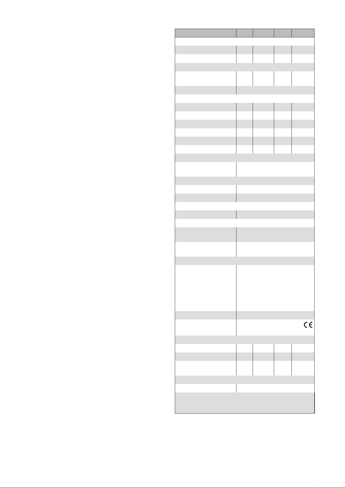
Technical data
Uniswitch ZL Min. Typ. Max. Unit
Supply 24V DC SELV
Supply voltage 18 24 30 V DC
Current consumption 13 18 23 mA
Floating output
Switching capacity at
24 V DC
72 W
Minimum load 10 mA with 5 V DC
Input control
Central voltage active 8 24 36 V DC
Central current active 0.5 1 1.5 mA
Central voltage inactive -0.5 0 3 V DC
Local voltage active 8 24 36 V DC
Local current active 0.5 1 1.5 mA
Local voltage inactive -0.5 0 3 V DC
Enclosure
Dimensions Installation in flush-mounting
box, see Fig. 3
Degree of protection/safety class
In flush-mounting box IP 20
Safety class III
Connection
All connections Spring terminals
Terminals
Input,
output
0.5...1.5 mm2
Control line,
Push button line
0.2...0.5 mm2
Other
Test standards: EN 61000-6-2:2005
EN 61000-6-3:2007 + A1:2011
EN 60669-1:1999 + A1:2002 +
Corrigendum:2007 + A2:2008
EN 60669-2-1:2004 + A1:2009
EN 60669-2-1:2004/A12:2010
EN 62233:200
Location of use Clean ambient conditions
Conformity
Available at www.warema.de
Ambient conditions
Operating temperature 0 20 40 °C
Storage temperature 0 20 50 °C
Rel. humidity
(non-condensing)
10 40 85 %RH
Article numbers
Uniswitch ZL UP 1002 473
WAREMA Renkhoff SE
Hans-Wilhelm-Renkhoff-Strasse 2
97828 Marktheidenfeld

3
890383_b•en•01.05.2014 We reserve the right to carry out improvements
20.4 mm
48.5 mm
48.5 mm
Fig. 3 Dimensions of the Uniswitch ZL for installation in a flush-mounting box
PP
X1
0
0
P
+
+
Aus-
gang
X2
Lokal
24V= X3
X4
Zentral
24V=
Ein-
gang
Uniswitch
ZL
Control line
Attention!
Supply voltage 24 V DC
must be SELV voltage in
accordance with VDE 0700-1
or DIN EN 60335-1.
2
2
3
3
1
1
bk
bn
bl
gnyl
PE
N
L
2
31
M 1~
Motor 1
00
0
++
+
NNN L L
MSE
Kompakt I
3,15 AT
UP
DOWN
+ 24 V DC
0 V
P
Power line
230 V AC 50 Hz / 16 A
F
Legend:
2 x 2 x 0,8 mm ∅ screened, single wired
H05RR-F4G 0,75 mm2 bk, Type WAREMA
3 x 1,5 mm2
UP
DOWN
0 V
For further information, see
documentation to wiring
diagrams "Anschlusspläne"
Art.no. 816 345
10
11
12
13
14
15
16
DOWN
UP
0 V
24 V DC
P0
Control
E
Floor distribution control
Standard / Run time
Connection:
Floating contacts of the sun
shading control system/
Floor distribution control Compact
24 V DC
230 V AC
24 V DC
DOWN
UP
E
P/C
P
Fig. 4 Wiring diagram: galvanic isolation in case of long control lines

890383_b•en•01.05.2014We reserve the right to carry out improvements
4
2
2
3
3
1
1
bk
bn
bl
PE
N
2
2
3
3
1
1
bk
bn
bl
2
2
3
3
1
1
bk
bn
bl
PE
N
Multiple series connection
2
31
M 1~
2
31
M 1~
2
31
M 1~
Group button
(Motor 1 + 2)
Single push button
(Motor 3)
Single circuit
Motor 1 Motor 3
Motor 2
00++ P00++ P
00++ P
NNN NNN NNN
MSE
Kompakt 1
3,15 AT
MSE
Kompakt 1
3,15 AT
MSE
Kompakt 1
3,15 AT
L
L
L LL LL L
AP
AP
AP
gnyl
gnyl
gnyl
to next MSE
Power line
230 V AC
to next MSE
Attention!
Only one drive may be
connected per MSE!
Power line
230 V AC 50 Hz / 16 A
F
PP
Legend:
4 x 2 x 0,8 mm ∅ screened, single wired
2 x 2 x 0,8 mm ∅ screened, single wired
H05RR-F4G 0,75 mm2 bk, Type WAREMA
3 x 1,5 mm2
UP
DOWN
+
UP
DOWN
UP
DOWN
+ 24 V DC
0 V
UP
DOWN
+ 24 V DC
0 V
PP
X1
0
0
P
+
+
Aus-
gang
X2
Lokal
24V= X3
X4
Zentral
24V=
Ein-
gang
Uniswitch
ZL
To additional
units
Push button for operating
the downstream unit
P
PP
0V
+
0V
+
Downstream unit
0 V
For further information, see
documentation to wiring
diagrams "Anschlusspläne"
Art.no. 816 345
10
11
12
13
14
15
16
DOWN
UP
0 V
24 V DC
P0
Control
E
Floor distribution control
Standard / Run time
Connection:
Floating contacts of the sun
shading control system/
Floor distribution control Compact
24 V DC
230 V AC
24 V DC
DOWN
UP
E
P/C
Attention!
Supply voltage 24 V DC
must be SELV voltage in
accordance with VDE 0700-1
or DIN EN 60335-1.
- Group size max. 200 motor control units (see voltage drop diagram)
- Control line length, see voltage drop diagram
- The length of the supply line is primarily limited by the total motor current.
The number of the possible drives per circuit depends essentially on their
current consumption and the inline fuse.
- Max. current capacity of the MSE Kompakt 1 AP, see "Technical Data".
- Only pushbuttons may be used.
Fig. 5 Formation of additional groups in control line systems
Other WAREMA Control Unit manuals

WAREMA
WAREMA WMS WebControl User manual

WAREMA
WAREMA MSE Haustechnik ZL User manual

WAREMA
WAREMA GA Kompakt User manual

WAREMA
WAREMA Omnexo User manual

WAREMA
WAREMA MSE Compact 2 REG User manual

WAREMA
WAREMA WMS Splitter UP User manual

WAREMA
WAREMA GA Kompakt User manual

WAREMA
WAREMA GA Kompakt User manual

WAREMA
WAREMA Minitronic Dialog User manual

WAREMA
WAREMA climatronic WebControl User manual
Popular Control Unit manuals by other brands

Stahl
Stahl 9472/35 Series operating instructions

DELTA DORE
DELTA DORE TYXIA 4940 installation guide

MicroElektronika
MicroElektronika GSM click manual

Automationdirect.com
Automationdirect.com Productivity 1000 P1-15TD2 manual

Huawei
Huawei RRU3269 installation guide

ICP DAS USA
ICP DAS USA I-7188XA quick start guide