AURATON T-1 RT User manual

OWNER’S MANUAL
EN
www.auraton.pl
T-1 RT

2
Operaon under the load of up to 16A/10A
The AURATON RT receiver is equipped with a relay capable of operang with
the load of up to 16A/10A. Its low-sparking technique of switching mains
voltage contributes to the low wear of relay contacts.
Pre-installed lithium baery
Wireless temperature controller is equipped with a highest quality lithium
baery. Such baery provides an uninterrupted operaon me of a controller
AURATON T-1 up to 20 years. Standard temperature controllers usually require
the baery replacement. Therefore, the standard thermostat uses 20-40 baeries
within 20 years. This causes addional costs and introduces harmful substances
to the environment every year.
Interference-free communicaon between devices
The transmier and the receiver from the AURATON RT set communicate at the
frequency of 868 MHz. Very short, encrypted data transmission packets (approx.
0.004 s) ensure very ecient and interference-free operaon of the device.
LED
LED’s diode indicates the operaon mode status of the controller.
16A
Thank you for purchasing this modern, advanced, microprocessor-based temperature
regulator:
AURATON T-1 RT
AURATON H-1
Window handle (sold separately)
AURATON T-2
Thermometer (sold separately)
Optional elements of the system
A window handle, equipped with a posion sensor and a transmier, is an oponal
element of the system. This way the handle provides informaon about the state of the
window. The handle also dierenates between 4 widow posions: opened, closed,
pivoted and trickle venlated (micro-venlaon). The handle transmits informaon to the
RT receiver that controls the relay, e.g. switching o a heater in the event of opening the
window or lowering the temperature down to 3°C to conserve energy. One RT receiver
operates with max 25 handles.
An oponal element of the system allowing for controlling temperature in a room other
than that with the AURATON T-1 regulator.
Detailed informaon about oponal elements of the system are included in a secon
“Operang rules”.

3
Description of the AURATON T-1 receiver
Wireless temperature controller.
Front Back
AURATON T-1 is equipped with pre-installed lithium baery. Life span of
the baery is up to 20 years.
ATTENTION: unchangeable baery.
diode indicang
data transmission
holes for xing the wall
mounng holder
diode indicang
pairing
boom indicang
pairing with
a receiver
temperature
setpoint knob
temperature
sensor
– setpoint
of anfreeze
temperature (7°C)

4
Description of the AURATON RT receiver
Legend - description of LED signalling
The AURATON RT receiver works with the wireless AURATON T-1 controller. The received
is installed near the heang or air condioning device and may work with the load of
16A/10A.
mounng hole
detachable 230V power
supply connecon
terminals
detachable control
connecon terminals
mounng hole
power buon
power supply
diode
buon for unpairing devices
diode indicang that
the actuator device has
been switched on
diode indicang that
the actuator device has
been switched o
buon for pairing
devices with the
RT receiver
The LED light’s green – the output device is o
(the contacts COM and NC are closed).
The LED light’s red – the output device is on
(the contacts COM and NO are closed).
The LED ashes green – the RT receiver awaits the device to be paired
(chapter: “Pairing the AURATON T-1 wireless regulator and the RT
receiver”).
The LED ashes red – the RT receiver awaits the device to be
deregistered (chapter: “Deregistering the regulator from the RT
receiver”).
Green power supply diode – the RT receiver is switched on.
The LED ashes alternang red and green:
ALARM - the RT receiver has lost connecon with one of the paired
devices (chapter “Special situaons”).
RESET - receiver deregisters all previously paired devices
(chapter “Deregistering all devices paired with the RT receiver”).
5
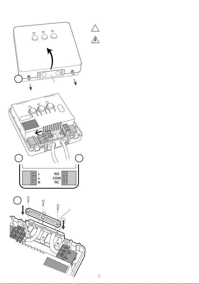
Installation of the AURATON RT receiver
CAUTION! The cables delivered in a set
together with the controller are suitable
for maximum loads equal to 2.5 A.
If devices with higher power are
connected, the cables should be replaced with
ones of appropriate cross-secons.
NOTE: When installing an AURATON RT receiver,
make sure that the power supply is switched o.
The receiver should be installed by a professional.
cable e
clamp
mounng plug NOTE: In the permanent system of the building
there must be a switch and an overcurrent
protecon.
NOTE: In order to facilitate installation, the
terminals are fitted with extendable clamps.
Before cable connecons are made, they can be
disconnected from the controllers. The cables
may be routed from the boom of the receiver by
breaking out holes in the mounng cover or from
the back of the receiver if the cables are extended
from the wall. In order to connect the cables from
the back, the cover must be broken out.
1. Take off the cover of the front part of
the AURATON RT receiver by unscrewing the
screws half way out.
2. Connect the heang device to the terminals
of the control connection of the AURATON
RT receiver. Follow the service instrucon of
the heang device. The COM (common) and
NO (normally opened) terminals are used the
most oen.
3. Connect the power supply cables to the ter-
minals of the power supply connecon of the
AURATON RT receiver, in observance of safety
rules.
4. After the cables are connected, they must
be fixed with the “cable fastening holder”
and the covers must be screwed back to
the AURATON RT receiver.
!
1
23
4
6
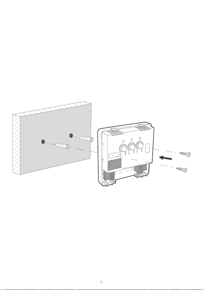
Fastening the AURATON RT receiver to a wall
In order to fasten the AURATON RT receiver on a wall:
NOTE: If the wall is wooden, there is no need to use wall plugs. In such a case, drill two
holes 2.7 mm in diameter instead of 5 mm, and screw the screws directly into the wood.
NOTE: The RT receiver cannot be placed in metal containers (e.g. an assembly box,
a metal enclosure of a heater) in order to not to interfere with its operaon.
1. Take o the covers from the front part of the controller
(see chapter “Installaon of the AURATON RT receiver”).
2. Mark the locaon of the holes for the fastening screws on the wall.
3. In the marked locaons, drill holes with diameters appropriate for the diameters
of the enclosed wall plugs (5 mm).
4. Put the wall plugs in the drilled holes.
5. Fasten the AURATON RT receiver to the wall using screws so that the receiver is well
fastened.

7
Selecting the proper location
for temperature regulator
Fastening the temperature regulator to the wall
NOTE: Before installing the appliance to the wall, it needs to be paired with a previously
connected receiver.
A controller T- 1 and a receiver purchased together, do not require pairing. The appliances
have been already pre-paired.
Proper operaon of the regu-
lator is greatly aected by its
locaon. Installing it in a place
with no air circulation or ex-
posed to direct sunlight causes
improper regulaon of temper-
ature. In order to ensure proper
operaon, the regulator must
be installed on an interior wall
of a building (paron wall). A
place should be selected that is
occupied most frequently, pro-
viding undisturbed circulaon
of air. Avoid heat radiang devices (television set, heater, refrigerator etc.) or places
exposed to direct sunlight. In order to avoid vibraon, do not place the regulator in close
vicinity of doors.
1. Drill two 5 mm holes in the wall (select
the span of holes with a wall-mounted
holder-enclosed to the set with con-
troller AURATON T-1
2. Insert the wall anchors to the holes
(aached to a set).
3. Fix the mounng plate to the wall.
4. Press to join the regulator ghtly
against the mounng holder(the holes
on a back part of the unit should be
suitable for snap-on of the holder).
Note: If the wall is made of wood, there is no need to use the wall anchors. Drill 2,7mm
holes in the wall instead of 5mm and screw the screws directly in a wood.

8
Pairing of the wireless AURATON RT controller with
the AURATON RT receiver
Deregistering the regulator from the RT receiver
Aer the receiver is connected to the network, the receiver must be switched on by
quickly pressing the power buon ( ). If the device is switched on, the green power
supply diode becomes illuminated and a single sound signal is emied. In order to switch
o the receiver, e.g. outside of the heang season, press the power buon and hold it
for 3 seconds unl a double sound signal is audible and the green power supply diode
is switched o and, consequently, the heang device is switched o.
In the event of an error during the pairing process, repeat steps 1 and 2. Should more
errors occur, deregister all devices by execung the RESET funcon of the RTH receiver
(see “RESET – Deregistering all devices paired with the RT receiver”) and aempt to pair
the device again.
NOTE: One receiver can have only one temperature regulator assigned.
NOTE: The AURATON T1 wireless temperature regulator sold with the AURATON RT
receiver is already paired. Devices sold separately require “pairing”.
1. Pairing of the AURATON T-1 controller with the AURATON RT receiver is iniated by
pressing the right pairing buon (green triangle – ) a single sound signal is emied – on
the AURATON RT receiver and by holding it pressed for at least 3 s unl the LED diode
starts blinking with green light (double sound signal) – then the buon must be released.
The AURATON RT receiver waits for pairing for 120 seconds. Aer that me, it auto-
macally returns back to normal operaon.
2. Press the pairing buon ( ) placed on the rear side
of housing and hold it for about 2 seconds. When LED
diode ( ) will starts ashing red stop pressing the buon.
3. A properly completed pairing process is signalled by the
LED on the AURATON RT receiver no longer ashing
green and the receiver reverng back to normal
operaon.
1. Deregistering the T-1 regulator from the RTH receiver is iniated by pressing the right
deregistering buon (marked with a red triangle – ) on the RTH receiver and holding
it for at least 2 seconds, unl the LED starts ashing red, and then releasing the buon
The AURATON RTH receiver waits for deregistering for 120 seconds. Aer that me,
it automacally returns back to normal operaon.
LED

9
RESET – Deregistering all devices paired
with the RT receiver
Signalling operation and reception
of data packet
In order to deregister all devices paired with the RTH receiver, simultaneously press both
the pairing and the deregistering buon ( and ) and hold them for at least 5 seconds
unl the LED ashes alternang red and green. Then release both buons
A properly completed process of deregistering all devices is signalled after approx.
2 seconds by the LED colour changing to green and then switching it o for a short
period of me.
Each radio transmission received by the AURATON RT receiver from the paired device
is signalled by a temporary change of LED colour to orange. Switching on the relay
is signalled by the LED lit red, whereas switching it o is signalled by the LED lit green.
In the event of an error during the deregistering process, repeat steps 1 and 2. Should
more errors occur, deregister all paired devices (see “RESET – Deregistering all devices
paired with the RT receiver”) and aempt to pair the device again.
NOTE: If aer execung the RESET funcon the RT receiver is disconnected from power
supply and then connected again, the receiver will automacally enter “pairing” mode
for 120 seconds. A newly purchased RT receiver without any factory-paired devices
(i.e. not the one bundled with the regulator) will behave the same way.
ATTENTION:
Pressing any buon is signaled by a short beep.
2. Press the pairing buon ( ) placed on the rear side of housing and hold it for about
2 seconds. When LED diode ( ) will starts ashing red stop pressing the buon.
3. A properly completed deregis-tering process is signalled by the LED on the AURATON RT
receiver no longer ashing red and the receiver reverng back to normal operaon.

10
Cooperation of the RT receiverwith
a heating device
Basic conguraon of devices
Receiver connected
to the heang device
Wireless thermometer
(sold separately)
Window handle
(sold separately)
Wireless
temperature
controller
heang device
A simplied schematic of connecting the AURATON RT
receiver with the heating device
AURATON RT AURATON T-2 AURATON H-1AURATON T-1
Addional
system devices
Setting the anti-freezing temperature
A controller is equipped with anfreeze mode .
This operaon mode results in maintaining the room temperature amounng 7 °C. It is
used during longer absence to prevent freezing of water in heang installaon.

11
Cooperation of the AURATON RT receiver with the
AURATON T-1 regulator and/or the AURATON T-2 thermometer
The operaon of temperature regulaon in the receiver is based on the binary algorithm
(on/o) using one or two sensor elements.
• The AURATON T-1 regulator allows for seng and/or monitoring the temperature.
• The AURATON T-2 thermometer provides informaon about the current temperature
only, without the capability of changing it manually.
A) The manual setpoint – pairing the AURATON T-1 regulator with the RT receiver allows
for seng the temperature manually and controlling it in the locaon of the fastening
of the T-1 regulator.
B) The remote setpoint – if the T-2 thermometer is addionally paired with the RT receiver,
the AURATON T-1 regulator retains the capability of temperature seng, however its
control is performed with the paired T-2 thermometer only. This feature allows for
regulang the temperature in a room other than the one where the AURATON T-1
regulator is placed.
An example: you want the temperature in the “children’s room” to be always at 22°C,
however you do not want children to be able to change it - in that room, you install
the T-2 thermometer, and the AURATON T-1 regulator in e.g. the kitchen. This way the
temperature in the “children’s room” will always be at 22°C regardless of temperature
uctuaons in the kitchen.
C) The factory setpoint (20°C) – if the T-2 thermometer is the only device paired with
the RT receiver, it is not possible to set the temperature manually, and the RT receiver
maintains the factory temperature setpoint of 20°C.
NOTE!
1. The sequence of pairing the AURATON T-1 regulator and the T-2 thermometer is very
important. If you want to maintain the remote setpoint, you must rst pair the AU-
RATON T-1 with the RT receiver, and then the T-2 thermometer. Reversing the pairing
sequence will cause automac deregistering of the previously paired T-2 thermometer
and entering the mode of operaon described in item A.
2. The RT receiver can operate with one AURATON T-1 regulator and/or one T-2 thermom-
eter only. Pairing a new regulator causes deregistering the previously paired regulator
and the T-2 thermometer. Pairing a new T-2 thermometer causes deregistering the
previously paired T-2 thermometer only.
3. The T-1 regulator and/or the T-2 thermometer can operate with an unlimited number
of receivers, e.g. one regulator can simultaneously control two independent heang
devices.

12
Cooperation with the AURATON R25 RT regulator and/or the
AURATON T-2 thermometer as well as the AURATON H-1 handles
By default, the AURATON RT receiver does not have any AURATON H-1 handle or AURA-
TON W-1 window posion sensor paired, therefore the relay is controlled by the paired
AURATON T-1 regulator and/or the AURATON T-2 thermometer. When at least one H-1
handle is paired with the RT receiver, the relay is controlled in the following manner:
A) The window is closed or trickle-venlated (micro-venlaon).
When the H-1 window handles is paired with the receiver, and all windows are closed
or trickle-venlated, the relay sll maintains the setpoint from the paired AURATON T-1
regulator and/or the T-2 thermometer.
B) The window is pivoted.
If at least one window is pivoted, the temperature set in the AURATON T-1 regulator
is lowered in AURATON RT receiver down to 3°C. This state will be maintained unl
closing. This state will last unl all windows are closed or trickle-venlated.
C) The window is opened.
When you open a window equipped with the H-1 handle paired for longer than
30 seconds, the relay in the AURATON RT receiver is switched o, as is the connected
heang device. If all the assigned windows are again in a state other than “opened”,
the RT receiver returns to normal cooperation with the AURATON T-1 regulator
and/or the T-2 thermometer no earlier than 90 seconds aer switching o the relay.
The purpose of this delay is to prevent too rapid transions of the connected heang
devices between the ON and OFF states. However, if the temperature in the room drops
below 7°C, the relay inside the receiver is switched on regardless of the posions of
windows in order to prevent the room from freezing.
D) The signal is lost.
When the RT receiver has lost the signal from the H-1 handle paired (3 consecuve
transmissions are lost), it changes the status if this window to “closed”. When the
transmission is restored, the H-1 handle is again properly read o by the RT receiver.

13
RESET of the regulator
Special situations
Unique features of AURATON T-1
Pressing the RESET buon ( ) causes the me and day seng to be erased, and the
regulator to be restarted.
• When 3 consecuve transmissions (aer 15 minutes) from the AURATON R25 RT regu-
lator and/or the T-2 thermometer are lost, an error is signalled on the RT receiver (LED
ashing connuously red and green). The RT receiver starts execung the ON - OFF
cycle memorised during the last 24 hours of operaon unl the problem is removed.
• When both signals return (from the AURATON R25 RT regulator and the T-2 thermom-
eter), the error is cancelled and the receiver enters its normal mode of operaon.
• When only the T-2 thermometer signal returns, the receiver uses the last memorised
setpoint value and maintains it while signalling the error.
• When the H-1 handles, the T-2 thermometer and the AURATON R25 RT regulator (the
temperature is measured with the T-2 thermometer) are paired with the receiver,
then maintaining the work cycle from the last 24 hours occurs only aer losing the
signal from the T-2 thermometer. When only the signal from the AURATON R25 RT
is missing, the RT receiver automacally maintains the last memorised setpoint from
the AURATON R25 RT regulator and also signals an error.
• When you have only the H-1 handles and the T-2 thermometer paired with the RT
receiver without the AURATON R25 RT regulator, the RT receiver maintains a constant,
factory-dened temperature of 20°C. If you pivot any window equipped with the H-1
handle paired with the receiver, a temperature of 17°C is maintained. If you open
any window equipped with the H-1 handle paired with the RT receiver, the receiver
switches o the heang device, but will switch it back on when the temperature falls
below 7°C.
• A pre-installed lithium baery, provides an interrupted operaon up to 20 years.
• Switching the relay is synchronised with the wave of the 230 V mains voltage in order
to ensure that closing and opening contacts of the relay occurs around the zero-cross-
ing point. This prevents the occurrence of an electric arc, signicantly extending the
relay service me.
• The AURATON RTH receiver is equipped with a unique algorithm for analysing the
ON - OFF cycles. The enre heang cycle from the last 24 hours is recorded in the
memory of the RTH receiver. In the event of losing communicaon with the AURA-
TON T-1 RTH regulator and/or the T-2 thermometer, the RTH receiver automacally
executes the ON - OFF cycle memorised during the last 24 hours. This provides me
for restoring transmission (removing interferences) or xing the T-1 regulator and/or
the T-2 thermometer without a signicant deterioraon of thermal comfort condions
in the controlled spaces.
14
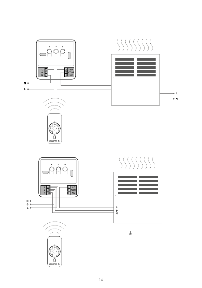
The AURATON RT receiver connection schematics
CONTROL HEATING
DEVICE
e.g. a gas furnace
~230V AC
PROTECTIVE
ELECTRIC
HEATING
DEVICE
MAX ~230V 16A

15
Disposing of the devices
Technical specications
Additional information and notes
The devices are marked with the crossed waste bin symbol. According to Eu-
ropean Direcve no. 2002/96/EU and the Act concerning used up electric and
electronic equipment, such a marking indicates that this equipment may not
be placed with other household generated waste.
The user is responsible for delivering the devices to a recepon point for used-up
electric and electronic equipment.
• The AURATON T-1 regulator and/or the T-2 thermometer must be installed at least 1 metre
from the RT receiver (too strong a signal from thetransmiers can cause interference).
• At least 30 seconds must elapse between switching the relay o and on.
• Data transmission from the AURATON T-1 regulator to the receiver occurs upon each
change of 0.2 °C of the surrounding temperature. When the temperature is stable,
the regulator sends heart-beat data every 5 minutes (which is signalled with the LED
blinking orange on the RT receiver).
• In the event of a power outage, the RT receiver will switch o. When power is restored,
the heang device is switched on automacally, and the RT receiver awaits a signal from
the paired transmiers (this signal should be received within 5 minutes of restoring
power). Aer receiving the signal, the RT receiver enters the normal mode of operaon.
• The RT receiver cannot be placed in metal containers (e.g. an assembly box, a metal
enclosure of a heater) in order to not to interfere with its operaon.
Working temperature range: 0 – 45°C
Temperature measurement range: 7°C; 15 – 35°C
Temperature levels: 1
Anfreeze temperature: 7°C
Working mode control: LED
Maximum load: resisve 16 A
inducve / capacive 10 A
Power supply T-1: pre-installed lithium baery
Power supply RT: 230V AC, 50Hz
Radio frequency: 868 MHz
Operaon range RT:
in a typical building, with standard construcon
of walls – approx. 30 min
an open space – up to 300 m
www.auraton.pl
ver. 20190408
Table of contents
Other AURATON Thermostat manuals

AURATON
AURATON 1300 User manual

AURATON
AURATON 200 RTH User manual

AURATON
AURATON Libra User manual

AURATON
AURATON S03 RTH User manual

AURATON
AURATON 2020 User manual

AURATON
AURATON 2005 TX User manual

AURATON
AURATON 2100 TX User manual

AURATON
AURATON 2005 User manual

AURATON
AURATON 3003 User manual

AURATON
AURATON Auriga User manual


Popular Thermostat manuals by other brands

Honeywell
Honeywell RTH111 series user guide

VDH
VDH MC 785-DF KLIMA operating manual

Nailor
Nailor UNI2-VAV Installation and operation manual

Watts
Watts Tekmar WiFi Thermostat 561 Installation & operation manual

Venstar
Venstar T4950SCH-IAQ Owner's manual and installation instructions

Honeywell
Honeywell RTH2510/RTH2410 Series operating manual


