AURATON R30 RT User manual

R30 RT
OWNER’S MANUAL
EN
www.auraton.pl


3
Thank you for purchasing this modern, advanced, microprocessor-based temperature
regulator:
8 independently seable temperatures for day and night me
on his or her requirements.
Operaon under loads up to 16A/10A
the load up to 16 A. Its low-sparking technique of switching mains voltage
contributes to the low wear of relay contacts.
Interference-free communicaon between devices
using the frequency of 868 MHz. Very short, encrypted data transmission
-
Calibraon of temperature indicaons (oset)
Backlit LCD display
in a poorly lighted room. (Features 3 selectable backlight colours)
AURATON H-1
Window handle (sold separately)
AURATON T-2
Thermometer (sold separately)
AURATON R30 RT
LCD
Optional elements of the system
16A
operates with max 25 handles.
than that with the AURATON R30 RT regulator.

4
Description of the AURATON R30 RT
temperature regulator
Display
RESET
fastening
hole
programming
(AA LR6 1.5 V)
5
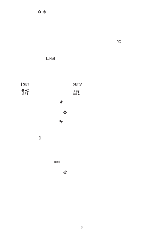
1. Day of week ( )
Indicates the current day of week. Every day is assigned a number.
2. Temperature
in the room it is installed in.
3. Temperature unit
).
4. Clock
Time is displayed in the 24-hour format.
5. Program number ( )
6. Seng mode indicator ( SET )
The word SET
thermostat:
7. Manual control indicator ( )
8. An-freeze mode indicator ( )
9. Vacaon mode indicator ( )
(See chapters: “Temperature programming” and “Vacaon mode”).
10. Low baery ( )
.
NOTE: In order to preserve the parameters programmed, duraon of the replace-
ment operaon must not to exceed 30 seconds.
11. Transmission symbol ( )
12. Relay acvaon indicator ( )
when the controlled device is turned on (e.g. a heater).
13. Informaon about operaon of the regulator ( INFO )
NOTE:
(INFO 24H, INFO TOTAL).
- temperature
- program- day of week
INFO
INFO 24H
INFO TOTAL

6
Description of the AURATON RT receiver
The AURATON RT receiver works with the wireless AURATON R30 RT controller. The
load of 16A/10A.
detachable 230V power
terminals
detachable control
power supply
diode
the actuator device has
been switched on
the actuator device has
devices with the
RT receiver
Legend – description of LED signalling
The LED light’s green
The LED light’s red – the output device is on
The LED ashes green – the RT receiver awaits the device to be paired
(chapter: “Pairing the AURATON R30 RT wireless regulator and the RT
receiver”).
The LED ashes red – the RT receiver awaits the device to be
deregistered (chapter: “Deregistering the regulator from the RT
receiver”).
Green power supply diode – the RT receiver is switched on.
The LED ashes alternang red and green:
ALARM
devices (chapter “Special situaons”).
RESET - receiver deregisters all previously paired devices
(chapter “Deregistering all devices paired with the RT receiver”).
7
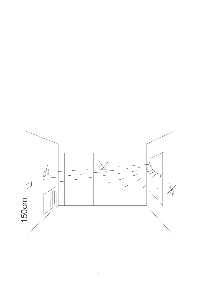
Selecting the proper location for temperature
regulator
-
(television set, heater, refrigerator etc.) or places exposed to direct sunlight. In order to
8
1
23
4
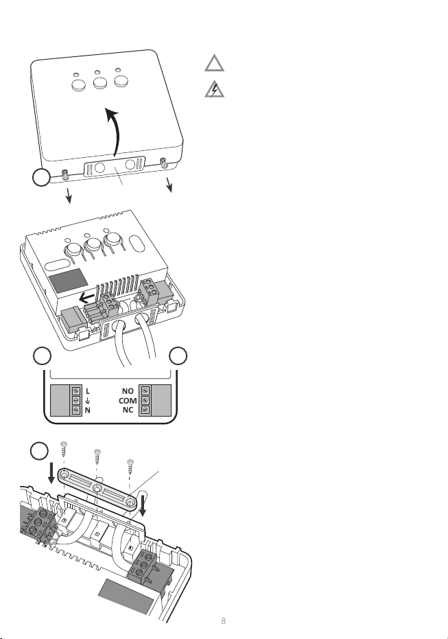
Installation of the AURATON RT receiver
CAUTION! The cables delivered in a set
together with the controller are suitable
for maximum loads equal to 2.5 A.
If devices with higher power are connect-
ed, the cables should be replaced with ones
NOTE: When installing an AURATON RT receiver,
The receiver should be installed by a professional.
clamp
NOTE: In the permanent system of the building
there must be a switch and an overcurrent pro-
NOTE: -
-
nected from the controllers. The cables may be
-
back of the receiver if the cables are extended
from the wall. In order to connect the cables
from the back, the cover must be broken out.
1.
AURATON RT receiver by unscrewing the
screws half way out.
2.
(normally opened) terminals are used the
3. -
AURATON RT receiver, in observance of safety
rules.
4.
and the covers must be screwed back to the
AURATON RT receiver.
!

9
Fastening the temperature regulator to the wall
NOTE: If the wall is wooden, there is no need to use wall plugs. In such a case, drill two
holes 2.7 mm in diameter instead of 6 mm, and screw the screws directly into the wood.
1.
to mark the spacing between these holes).
2.
3.
4.
key-hole in the rear wall of the regulator).
5. Screw in the right screw, making sure it holds the regulator securely.

10
Fastening the AURATON RT receiver to a wall
In order to fasten the AURATON RT receiver on a wall:
NOTE: If the wall is wooden, there is no need to use wall plugs. In such a case, drill two
holes 2.7 mm in diameter instead of 5 mm, and screw the screws directly into the wood.
NOTE: The RT receiver cannot be placed in metal containers (e.g. an assembly box,
a metal enclosure of a heater) in order to not to interfere with its operaon.
1.
(see chapter “Installaon of the AURATON RT receiver”).
2.
3.
of the enclosed wall plugs (5 mm).
4. Put the wall plugs in the drilled holes.
5. Fasten the AURATON RT receiver to the wall using screws so that the receiver is well
fastened.
11
Pairing of the wireless AURATON R30 RT
controller with the AURATON RT receiver
Unpairing of the controller and the RT receiver
). If the device is switched on, the green power
In the event of a pairing error, steps 1 and 2 must be repeated. If more errors occur, all
devices must be unpaired by RESETTING the AURATON RT receiver (see „RESET - Unpairing
all devices paired with the AURATON RT receiver”) and then an aempt must be made to
pair the devices again.
NOTE: Only 1 temperature controller may be paired with one receiver.
NOTE: If the wireless controller AURATON R30 RT is sold together with the
AURATON RT receiver, the two devices are factory-paired. Devices purchased sepa-
rately must be paired.
1.
The AURATON RT receiver waits for pairing for 120 seconds. Aer this period, it auto-
macally returns to normal operaon.
2. On the AURATON R30 RT, the
transmission symbol (
controller emits the pairing signal for 5 seconds.
3.
no longer blinking green, emission of a single sound signal, and the receiver switching
1. Unpairing of the AURATON R30 RT controller from the AURATON RT receiver is in-
) on the receiver and holding it for
released. The sound signal works in the same way as during pairing, i.e. when a buon
is pressed, a short sound is emied and another short sound signal aer 3 seconds.
The receiver waits for pairing for 120 seconds. Aer this period, it automacally returns
to normal operaon.

12
RESET – Unpairing all devices paired with
the AURATON RT receiver
Signaling of operation and receipt of data packets
In order to unpair all devices paired with the AURATON RT receiver, simultaneously press
( and ) for at least 5 seconds,
another short signal 5 seconds later.
In the event of an unpairing error, steps 1 and 2 must be repeated. If more errors occur, all
devices must be unpaired (see „RESET – Unpairing all devices paired with the AURATON
RT receiver”).
NOTE: If the power supply of the AURATON RT receiver is switched o and then switched
on aer the RESET, the receiver automacally goes into the “pairing” mode for 120
seconds. A newly purchased (separately from the controller) AURATON RT receiver acts
in the same way if it has no factory-paired devices.
NOTE:
2. On the AURATON R30 RT, the
transmission symbol (
3.
longer blinking red, emission of a single sound signal, and the receiver switching to
13
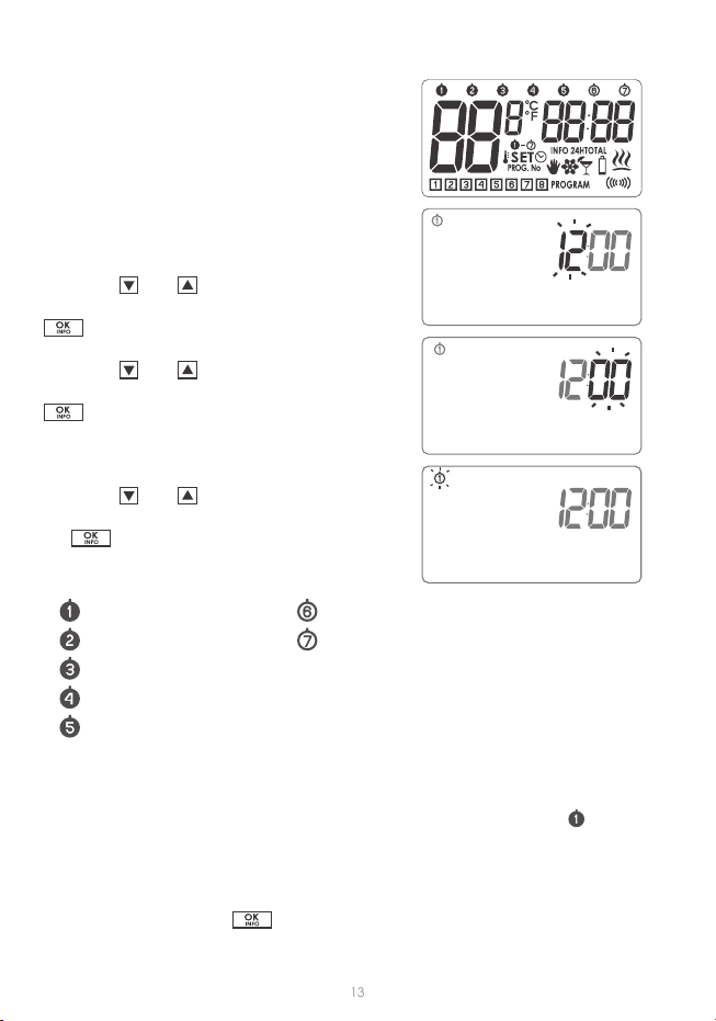
are displayed (display test) for one second;
number is displayed.
Using the and
Using the and
In the upper part of the display, the day of the
Using the and
the
Starting-up the regulator for the rst time
– Monday – Saturday
– Tuesday – Sunday
– Wednesday
– Thursday
– Friday
NOTE:
) as the day
of week.
NOTE:
equivalent to pressing the
14
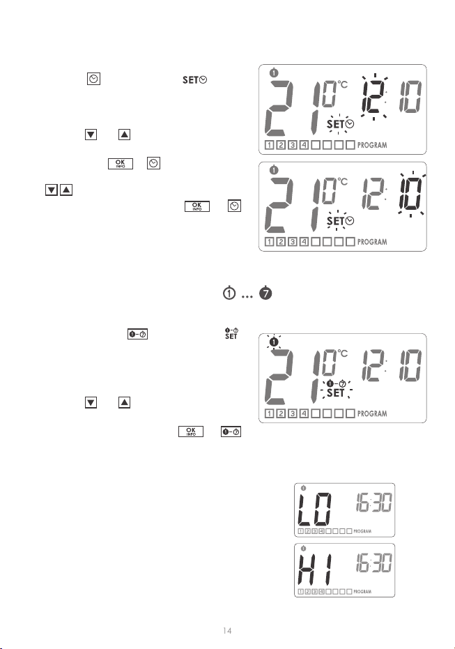
Setting the clock
Setting the day of week
LO / HI temperature
In order to set the clock:
1. Press the icon is
displayed, informing that the regulator has
2. Using the and
hour value.
3. Then press the or
( ) the desired minute value.
4. or
In order to set the day of week:
1. Press and hold the ,
icon is displayed, informing that the regu-
mode and one of the digits representing
2. Using the and
day of week.
3. or
If the surrounding temperature is lower than
5 °C, the display shows “LO”.
If the surrounding temperature is higher than
35 °C, the display shows “HI”.

15
Factory programs (for modicaon)
PROGRAMMING
The memory of the regulator allows for saving up to eight programs for weekdays, eight
programs for Saturday and the same for Sunday.
In order to start programming:
Press and hold the
icon is displayed.
1. Selecng a program
Using the and -
gram number to which you will assign the fol-
lowing parameters:
– temperature setpoint,
− day of week it applies to,
− me
Weekdays Saturday Sunday
6:00
8:30
15:00
23:00
6:00
23:00
6:00
23:00
Prog. Prog. Prog.
Start
me Start
me Start
me
Temperature Temperature Temperature

16
2. Assigning a day to the program
Press the
to the program. A segment with days of week will
Using the
3. Assigning temperature to the program
Press the
program.
The -
using the
The icon and the number of currently edited
4. Assigning starng me to the program
Press the -
the
The icon and the number of currently edited
5. Repeat the procedure for consecuve programs.
The icon and the number of currently edited
– for week days
– for Saturday
– for Sunday

17
manual temperature ( ) – within the range from 5°C to 30°C
) – within the range from 5°C to 30°C
) – within the range from 4°C to 10°C
1. Press the icon
is displayed with the symbol of the currently edited
kind of temperature.
2. Pressing the -
rently edited kind of temperature.
3. Set the desired temperature value in the currently
edited kind of temperature, using the but-
tons.
4. -
Programming the manual ,
vacation and anti-freezing temperature
NOTE:
1. Programs with the same program numbers, but assigned to other days of week can
E.g.: program 1 on Saturday can start at 08:00,
and program 1 on Sunday can start at 10:00.
2. to (from Monday to Friday) have the same programs.
3. On the same day of week, the next program should start at least a minute aer
the start of the previous one. Otherwise the regulator will renumber the programs
in order to preserve the chronology of temperature setpoints
4. For the selected day of week, the period of temperature programming cannot exceed
5.
D ELETING A PROGRAM:
To delete a selected program, set “dashes” in the tem-
Factory setting:
manual
18
the vacaon mode can be used.
(see chapter: “Temperature programming”).
1. Press the
and icons
2. Using the and
3.
The
the and -
4. .
you have to:
1. Press the and
value set as default. Use the
2. To leave the manual control mode, press the .
The “
Manual control
Vacation mode

19
Anti-freeze mode
Switching off the receiver for a period of time
Viewing the currently active program
Relay operating time counter
-
-
1. ” icon will appear on
the display.
2. or
Pressing the -
Pressing the segment and
all the parameters of the currently executed program (day of week, temperature and
Pressing the
Pressing the segment to appear, correspond-
NOTE:
mode.
NOTE:

20
Conguration settings:
backlight colour, hysteresis, delay, offset, clock calibration
1. BACKLIGHT COLOUR CHANGE
Flashing backlight indicates that you can change
the backlight colour with the
The regulator will proceed to change the next parameter.
2. HYSTERESIS CHANGE
Hysteresis is designed to prevent switching the con-
E.g. for the HI 2 hysteresis, when the temperature is set
to 20 °C, the boiler will be switched on at 19.8 °C, and
switched o at 20.2 °C. For the HI 4 hysteresis, when
the temperature is set to 20 °C, the boiler will be switched on at 19.6 °C, and switched
o at 20.4 °C
HI 2(factory seng)
HI 4
HI P – (see chapter “PWM operaon mode”).
.
next parameter.
3. OFFSET CHANGE
E.g. the temperature regulator indicates that the room temperature is 23°C, whereas
a egular mercurial thermometer placed alongside indicates 24°C. Changing oset by
+1 degree makes the regulator indicate the same temperature as the mercurial one.
OFFS.
within the range from
3.0 to 3.0 (factory seng is 0.0).
-
.
backlight
colour change
hysteresis
change
delay
change
oset
change
clock
calibraon
Table of contents
Other AURATON Thermostat manuals

AURATON
AURATON 2005 User manual

AURATON
AURATON 1300 User manual

AURATON
AURATON 2100 TX User manual

AURATON
AURATON S03 RTH User manual

AURATON
AURATON T-1 RT User manual

AURATON
AURATON 200 RTH User manual

AURATON
AURATON Libra User manual

AURATON
AURATON 2005 TX User manual

AURATON
AURATON 3003 User manual

AURATON
AURATON Auriga User manual


