AURATON 200 RTH User manual

www.auraton.pl
200 RTH
AURATON RTH
OFF
ON
IN
OUT
ALARM
RESET
dla oprogramowania w ver. F03 oraz F0A
AURATON 200 RTH
Instruction Manual

3
LCD
2
Thank you for purchasing the modern temperature controller based on an
advanced microprocessor.
AURATON 200 RTH
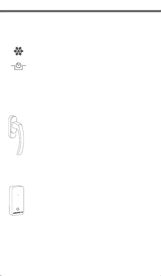
FrostGuard function:
Protects the interior from freezing
Enables cyclic reduction of set temperature
by 3°C for 6 hours.
Backlit LCD display
The backlit display enables device control even in dark rooms.
AURATON H-1
Window handle (sold separately)
A window handle, equipped with a position sensor and
a transmitter, is an optional element of the system. This way the
handle provides information about the state of the window.
The handle also differentiates between 4 widow positions:
opened, closed, pivoted and trickle ventilated (micro-
ventilation). The handle transmits information to the RTH
receiver that controls the relay, e.g. switching off a heater in the
event of opening the window or lowering the temperature down
to 3 °C to conserve energy. One RTH receiver operates with max
25 handles.
Optional elements of the system
AURATON T-2
Thermometer (sold separately)
An optional element of the system allowing for controlling
temperature in a room other than that with the AURATON 200
RTH regulator.
3
LCD
2
Thank you for purchasing the modern temperature controller based on an
advanced microprocessor.
AURATON 200 RTH
FrostGuard function:
Protects the interior from freezing
Enables cyclic reduction of set temperature
by 3°C for 6 hours.
Backlit LCD display
The backlit display enables device control even in dark rooms.
AURATON H-1
Window handle (sold separately)
A window handle, equipped with a position sensor and
a transmitter, is an optional element of the system. This way the
handle provides information about the state of the window.
The handle also differentiates between 4 widow positions:
opened, closed, pivoted and trickle ventilated (micro-
ventilation). The handle transmits information to the RTH
receiver that controls the relay, e.g. switching off a heater in the
event of opening the window or lowering the temperature down
to 3 °C to conserve energy. One RTH receiver operates with max
25 handles.
Optional elements of the system
AURATON T-2
Thermometer (sold separately)
An optional element of the system allowing for controlling
temperature in a room other than that with the AURATON 200
RTH regulator.
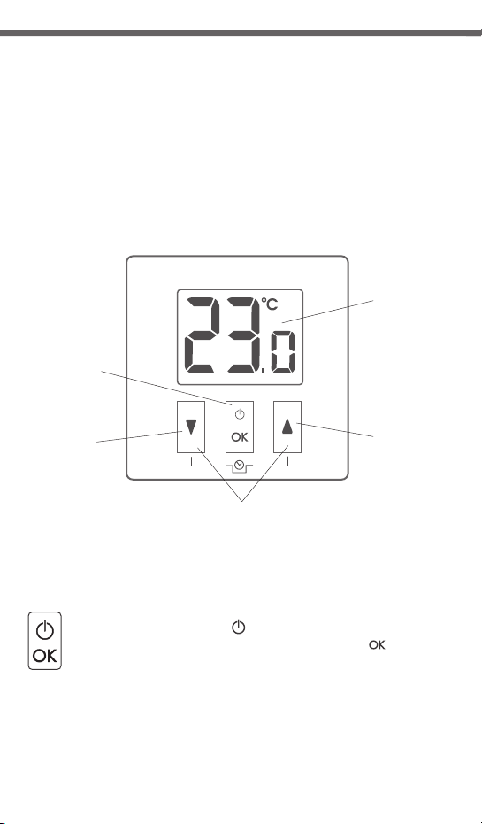
The front of the enclosure has a backlit LCD display and three function
buttons.
4
123
4
5
6
7
5
AURATON 200
LCD display
temperature
increase key
temporary temperature decrease
mode keys
acknowledge
or on/off key
temperature
decrease key
źhold – controller on/off ( )
źshort press – acknowledge temperature setting ( )
AURATON 200 RTH temperature
controller explained
4. Temporary temperature decrease mode programming
indicator ( )
WIndicates the temporary temperature decrease mode planned
by the user. Displayed when the mode is not executed but the
function of the temporary temperature decrease is active
(refer to "Temporary temperature decrease setting" section for
more details).
5. Controller power on indicator ( )
Indicates the operating status. Appears when the controller
device is started.
6. Transmission symbol ( )
Indicates communication with the receiver.
7. Battery exhausted ( )
Displayed when the battery voltage drops below the allowed
limit. Replace the battery as soon as possible.
Display screen
1. Temperature
In normal operating mode, the controller displays
the temperature of the room it is installed in.
2. Temperature unit ( )
Indicates temperature displayed in centigrade.
3. Temporary temperature decrease mode indicator ( )
Appears when the temporary temperature decrease program
is active.
6 7
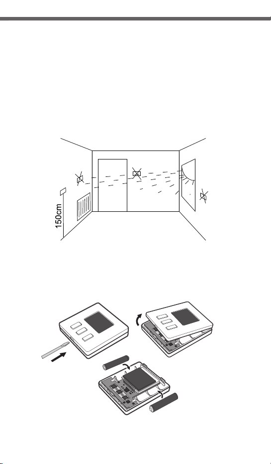
Selecting proper location for AURATON 200 RTH
temperature controller
Controller location largely affects its proper operation. When located in a
place without air circulation or exposed to direct sunlight, the controller may
not control the temperature properly. The controller should be located on an
internal wall of a building (partition wall) in a place with free air circulation.
Avoid locations near sources of heat (TV set, heater, refrigerator) or places
exposed to direct sunlight. Location near doors and the resultant vibration
may cause the controller to function improperly.
Battery installation / replacemen in AURATON 200 RTH
Battery sockets are located inside the controller on both sides of the display.
To install the batteries, remove the controller enclosure as shown in the
figure.
Place two AAA 1.5 V batteries in the battery socket observing
the correct polarity.
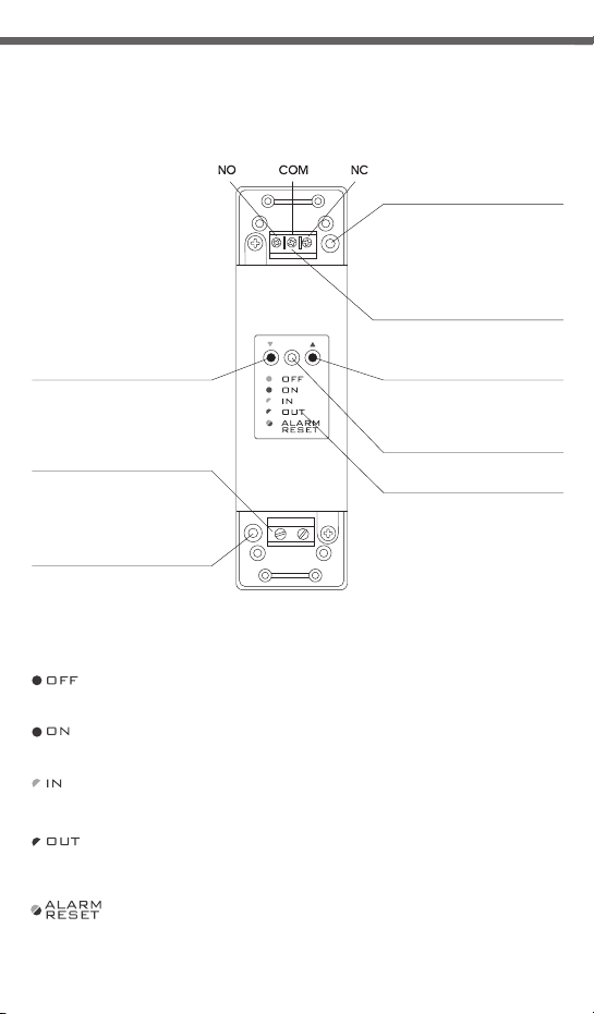
AURATON RTH
cable tie clamp
control connection terminal
(a terminal for fastening a two-core
cable of the heating or air conditioning
device to be controlled
button for deregistering
already paired devices
button for pairing devices
with the RTH receiver
LED indicating operation
of the device
cable tie clamp
power supply terminal
~230V AC
legend
The LED light’s green – the output device is off (the contacts COM
and NC are closed).
The LED light’s red – the output device is on (the contacts COM and
NO are closed).
The LED flashes green – the RTH receiver awaits the device
to be paired (chapter: “Pairing the AURATON 200 RTH wireless
regulator and the RTH receiver”).
The LED flashes red – the RTH receiver awaits the device
to be deregistered (chapter: “Deregistering the regulator from the
RTH receiver”).
The LED flashes alternating red and green:
ALARM - the RTH receiver has lost connection with one of the paired
devices (chapter “Special situations”).
RESET - receiver deregisters all previously paired devices - (chapter
“Deregistering all devices paired with the RTH receiver”).
Legend - description of LED signalling
hole for fastening the receiver
to the wall with a screw
hole for fastening the receiver
to the wall with a screw
Description of the AURATON RTH receiver
The AURATON RTH receiver cooperates with the AURATON 200 RTH wireless
receiver. The receiver is installed on the heating or air conditioning device and can
operate under the load of 16 A.
~230V AC
6 7
Selecting proper location for AURATON 200 RTH
temperature controller
Controller location largely affects its proper operation. When located in a
place without air circulation or exposed to direct sunlight, the controller may
not control the temperature properly. The controller should be located on an
internal wall of a building (partition wall) in a place with free air circulation.
Avoid locations near sources of heat (TV set, heater, refrigerator) or places
exposed to direct sunlight. Location near doors and the resultant vibration
may cause the controller to function improperly.
Battery installation / replacemen in AURATON 200 RTH
Battery sockets are located inside the controller on both sides of the display.
To install the batteries, remove the controller enclosure as shown in the
figure.
Place two AAA 1.5 V batteries in the battery socket observing
the correct polarity.
AURATON RTH
cable tie clamp
control connection terminal
(a terminal for fastening a two-core
cable of the heating or air conditioning
device to be controlled
button for deregistering
already paired devices
button for pairing devices
with the RTH receiver
LED indicating operation
of the device
cable tie clamp
power supply terminal
~230V AC
legend
The LED light’s green – the output device is off (the contacts COM
and NC are closed).
The LED light’s red – the output device is on (the contacts COM and
NO are closed).
The LED flashes green – the RTH receiver awaits the device
to be paired (chapter: “Pairing the AURATON 200 RTH wireless
regulator and the RTH receiver”).
The LED flashes red – the RTH receiver awaits the device
to be deregistered (chapter: “Deregistering the regulator from the
RTH receiver”).
The LED flashes alternating red and green:
ALARM - the RTH receiver has lost connection with one of the paired
devices (chapter “Special situations”).
RESET - receiver deregisters all previously paired devices - (chapter
“Deregistering all devices paired with the RTH receiver”).
Legend - description of LED signalling
hole for fastening the receiver
to the wall with a screw
hole for fastening the receiver
to the wall with a screw
Description of the AURATON RTH receiver
The AURATON RTH receiver cooperates with the AURATON 200 RTH wireless
receiver. The receiver is installed on the heating or air conditioning device and can
operate under the load of 16 A.
~230V AC

8 9
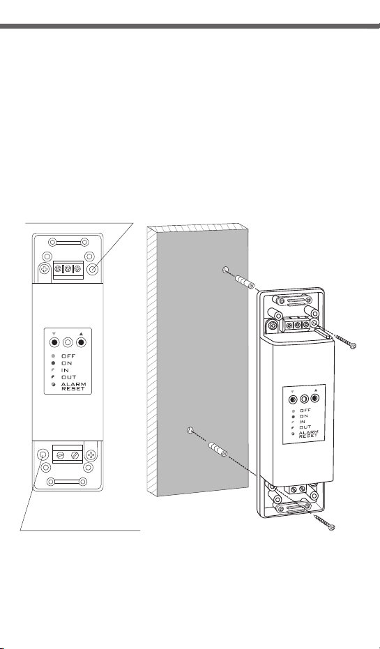
To fix the AURATON 200 controller to the wall:
1. Re m o v e t h e e n c lo s u re ( a s d e s cr i b ed o n t h e " B a t t e ry
installation/replacement" section).
2. Drill 2 holes diameter 6 mm in the wall (use the back of the controller
enclosure to set the right spacing of the holes).
Fixing the AURATON 200 RTH controller to the wall
3. Place plastic plugs in the drilled holes.
4. Screw the back of the controller enclosure to the wall with the two screws
provided.
5. Install the batteries and replace the controller enclosure.
NOTE: No expansion bolts are needed for wooden walls. Just drill holes diameter 2.7 mm
(instead of 6 mm) and screw the screws directly into the wood.
Alternative fixing methods
The controller can be mounted to a smooth surface with
e.g. two-sided adhesive tape.
The controller can also be placed in any location on an even surface on
a support at the back of the enclosure.
hole for a
mounting screw
hole for a
mounting screw
3. Connect the heating device to the
control connection terminals of the
AURATON RTH receiver.
Proceed in accordance with the service
manual of the heating device. Most
commonly, the COM (common) and NO
(normally open) terminals.
4. Connect power supply conductors to the
power supply terminals of the AURATON
RTH receiver, observing safety rules.
5. After connecting the conductors, they must
be secured with the cable tie clamps and
reinstall protective covers of the AURATON
RTH receiver.
Fastening the RTH receiver
1. Take off protective covers from the lower
and upper part of the AURATON RTH
receiver.
2. Take off cable tie clamps from the lower
and upper part of the AURATON RTH
receiver.
protective cover
cable tie clamp
NOTE: When installing the AURATON RTH
receiver its power supply must be
disconnected. It is recommended that the
installation is performed by a qualified
specialist.
NOTE:
The permanent electrical system
of a building must include a breaker
and an overcurrent protection.
~230V AC

8 9
To fix the AURATON 200 controller to the wall:
1. Re m o v e t h e e n c lo s u r e ( a s d e s cr i b ed o n t h e " B a t t e ry
installation/replacement" section).
2. Drill 2 holes diameter 6 mm in the wall (use the back of the controller
enclosure to set the right spacing of the holes).
Fixing the AURATON 200 RTH controller to the wall
3. Place plastic plugs in the drilled holes.
4. Screw the back of the controller enclosure to the wall with the two screws
provided.
5. Install the batteries and replace the controller enclosure.
NOTE: No expansion bolts are needed for wooden walls. Just drill holes diameter 2.7 mm
(instead of 6 mm) and screw the screws directly into the wood.
Alternative fixing methods
The controller can be mounted to a smooth surface with
e.g. two-sided adhesive tape.
The controller can also be placed in any location on an even surface on
a support at the back of the enclosure.
hole for a
mounting screw
hole for a
mounting screw
3. Connect the heating device to the
control connection terminals of the
AURATON RTH receiver.
Proceed in accordance with the service
manual of the heating device. Most
commonly, the COM (common) and NO
(normally open) terminals.
4. Connect power supply conductors to the
power supply terminals of the AURATON
RTH receiver, observing safety rules.
5. After connecting the conductors, they must
be secured with the cable tie clamps and
reinstall protective covers of the AURATON
RTH receiver.
Fastening the RTH receiver
1. Take off protective covers from the lower
and upper part of the AURATON RTH
receiver.
2. Take off cable tie clamps from the lower
and upper part of the AURATON RTH
receiver.
protective cover
cable tie clamp
NOTE: When installing the AURATON RTH
receiver its power supply must be
disconnected. It is recommended that the
installation is performed by a qualified
specialist.
NOTE:
The permanent electrical system
of a building must include a breaker
and an overcurrent protection.
~230V AC
10 11
To fasten the AURATON RTH receiver to the wall:
1) Remove protective covers from the lower and upper part of the regulator.
(See chapter: “Fastening the RTH receiver”).
2) On the wall, mark the location of holes for fastening screws.
3) In marked places, drill holes of a diameter corresponding to the bundled
wall plugs (5 mm).
4) Insert wall plugs into the drilled holes.
5) Screw in the RTH receiver to the wall with screws, making sure they hold the
receiver securely.
Fastening the RTH receiver to the wall
NOTE: If the wall is wooden, there is no need to use wall plugs. In such a case,
drill two holes 2.7 mm in diameter instead of 5 mm, and screw
the screws directly into the wood.
AURATON RTH
hole for fastening
the receiver to the wall with a screw
NOTE:The RTH receiver cannot be placed in metal containers
(e.g. an assembly box, a metal enclosure of a heater) in order to not to
interfere with its operation.
hole for fastening
the receiver to the wall with a screw
3. A properly completed pairing process is signalled by the LED on the AURATON
RTH receiver no longer flashing green and the receiver reverting back to normal
operation.
In the event of an error during the pairing process, repeat steps 1 and 2. Should
more errors occur, deregister all devices by executing the RESET function of the RTH
receiver (see “RESET - Deregistering all devices paired with the RTH receiver”)
and attempt to pair the device again.
NOTE: One receiver can have only one temperature regulator assigned.
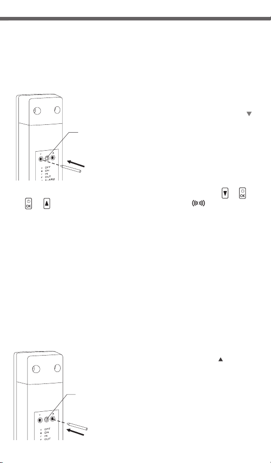
Pairing the AURATON 200 RTH wireless
temperature regulator with the RTH receiver
1.The process of pairing the 200 RTH regulator with
the RTH receiver is initiated by pressing the left
pairing button (marked with a green triangle - )
on the RTH receiver and holding it for at least
2 seconds, until the LED starts flashing green,
and then releasing the button.
The AURATON RTH receiver waits for pairing
for 120 seconds. After that time, it automatically
returns back to normal operation.
2. On the AURATON 200 RTH regulator, press and hold the buttons
for 6 seconds until the transmission symbol ( ) appears on the
display.
but OK
OK but radio
– or
–
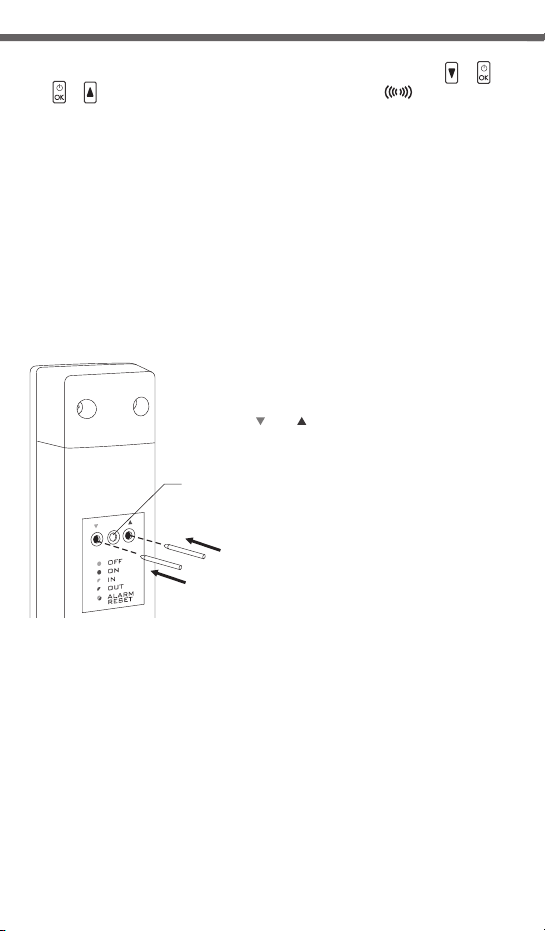
Deregistering the regulator from the RTH receiver
1.Deregistering the 200 RTH regulator from the RTH
receiver is initiated by pressing the right deregistering
button (marked with a red triangle - ) on the
RTH receiver and holding it for at least 2 seconds, until
the LED starts flashing red, and then releasing
the button.
The AURATON RTH receiver waits for deregistering for
120 seconds. After that time, it automatically returns
back to normal operation.
....
NOTE: The AURATON 200 RTH wireless temperature regulator sold with the
AURATON RTH receiver is already paired. Devices sold separately
require “pairing”.
LED
LED
10 11
To fasten the AURATON RTH receiver to the wall:
1) Remove protective covers from the lower and upper part of the regulator.
(See chapter: “Fastening the RTH receiver”).
2) On the wall, mark the location of holes for fastening screws.
3) In marked places, drill holes of a diameter corresponding to the bundled
wall plugs (5 mm).
4) Insert wall plugs into the drilled holes.
5) Screw in the RTH receiver to the wall with screws, making sure they hold the
receiver securely.
Fastening the RTH receiver to the wall
NOTE: If the wall is wooden, there is no need to use wall plugs. In such a case,
drill two holes 2.7 mm in diameter instead of 5 mm, and screw
the screws directly into the wood.
AURATON RTH
hole for fastening
the receiver to the wall with a screw
NOTE:The RTH receiver cannot be placed in metal containers
(e.g. an assembly box, a metal enclosure of a heater) in order to not to
interfere with its operation.
hole for fastening
the receiver to the wall with a screw
3. A properly completed pairing process is signalled by the LED on the AURATON
RTH receiver no longer flashing green and the receiver reverting back to normal
operation.
In the event of an error during the pairing process, repeat steps 1 and 2. Should
more errors occur, deregister all devices by executing the RESET function of the RTH
receiver (see “RESET - Deregistering all devices paired with the RTH receiver”)
and attempt to pair the device again.
NOTE: One receiver can have only one temperature regulator assigned.
Pairing the AURATON 200 RTH wireless
temperature regulator with the RTH receiver
1.The process of pairing the 200 RTH regulator with
the RTH receiver is initiated by pressing the left
pairing button (marked with a green triangle - )
on the RTH receiver and holding it for at least
2 seconds, until the LED starts flashing green,
and then releasing the button.
The AURATON RTH receiver waits for pairing
for 120 seconds. After that time, it automatically
returns back to normal operation.
2. On the AURATON 200 RTH regulator, press and hold the buttons
for 6 seconds until the transmission symbol ( ) appears on the
display.
but OK
OK but radio
– or
–
Deregistering the regulator from the RTH receiver
1.Deregistering the 200 RTH regulator from the RTH
receiver is initiated by pressing the right deregistering
button (marked with a red triangle - ) on the
RTH receiver and holding it for at least 2 seconds, until
the LED starts flashing red, and then releasing
the button.
The AURATON RTH receiver waits for deregistering for
120 seconds. After that time, it automatically returns
back to normal operation.
....
NOTE: The AURATON 200 RTH wireless temperature regulator sold with the
AURATON RTH receiver is already paired. Devices sold separately
require “pairing”.
LED
LED
12 13
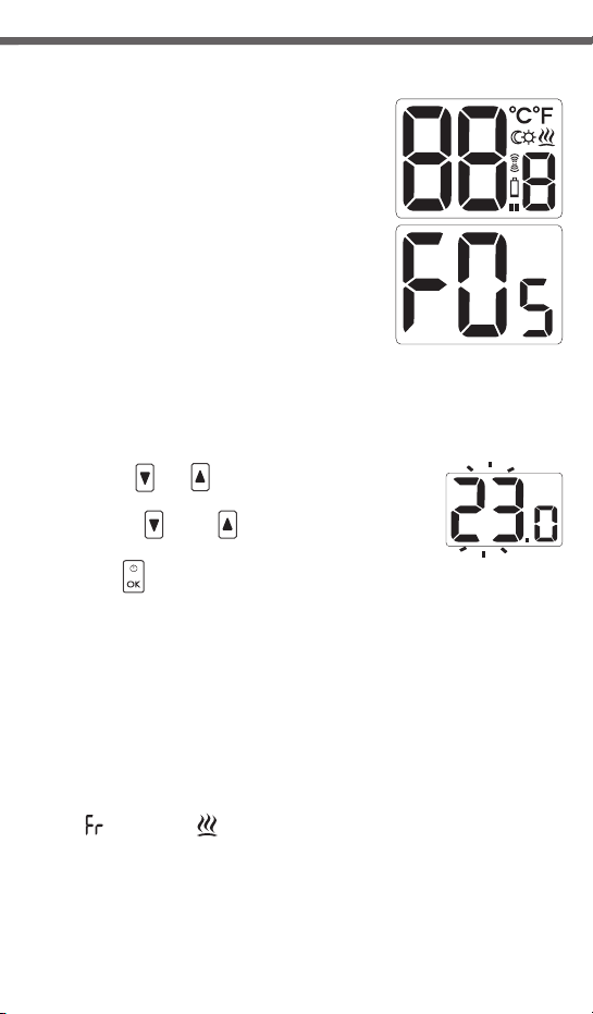
Starting the AURATON 200 RTH controller
for the first time
After correct installation on batteries, the LCD
will display, for a second, all segments (display
test) followed by the firmware version number.
After a while, the current temperature in the
room will be displayed. The controller is ready to
use.
Temperature setting
NOTE:
on and then the key function is activated.
To set the desired temperature in normal operating mode:
1. Press the key. The segment displaying
temperature will switch to edit mode and start blinking.
When pressing any function key for the first time, the backlight is turned
or
2. With the and keys, set the desired
temperature with the accuracy of up to 0.2°C.
3. Press the key to acknowledge selection.
<do> <up>
<do> <up>
FrostGuard function
AURATON 200 RTH controller features the special FrostGuard function to
protect the room from possible freezing.
The function is activated when the controller is switched off.
With the controller switched off, when the room temperature drops to 2°C,
the Fr ( ) and flame ( ) symbols will appear and signal will be sent to the
receiver to start heating. When the temperature raises to 2.2°C, the display
will turn off again and signal will be sent to the receiver to turn the heating off.
3. A properly completed deregistering process is signalled by the LED on the
AURATON RTH receiver no longer flashing red and the receiver reverting back
to normal operation.
In the event of an error during the deregistering process, repeat steps 1 and 2.
Should more errors occur, deregister all paired devices (see “RESET - Deregistering
all devices paired with the RTH receiver”) and attempt to pair the device again.
RESET - Deregistering all devices paired
with the RTH receiver
In order to deregister all devices paired with
the RTH receiver, simultaneously press both
the pairing and the deregistering button
( and ) and hold them for at least
5 seconds until the LED flashes alternating
red and green. Then release both buttons.
A properly co mpleted process of
deregistering all devices is signalled after
approx. 2 seconds by the LED colour
changing to green and then switching it off
for a short period of time.
.. ..
Signalling operation and reception
of data packet
Each radio transmission received by the AURATON RTH receiver from the paired
device is signalled by a temporary change of LED colour to orange. Switching on
the relay is signalled by the LED lit red, whereas switching it off is signalled by the
LED lit green.
LED
NOTE: If after executing the RESET function the RTH receiver is disconnected
from power supply and then connected again, the receiver will automatically
enter “pairing” mode for 120 seconds. A newly purchased RTH receiver without
any factory-paired devices (i.e. not the one bundled with the regulator) will
behave the same way.
2. On the AURATON 200 RTH regulator, press and hold the buttons
6 seconds until the transmission symbol ( ) appears on the
display. Release the button - the regulator transmits the pairing signal for 5
seconds.
but OK
OK but
radio
– or
–for
12 13
Starting the AURATON 200 RTH controller
for the first time
After correct installation on batteries, the LCD
will display, for a second, all segments (display
test) followed by the firmware version number.
After a while, the current temperature in the
room will be displayed. The controller is ready to
use.
Temperature setting
NOTE:
on and then the key function is activated.
To set the desired temperature in normal operating mode:
1. Press the key. The segment displaying
temperature will switch to edit mode and start blinking.
When pressing any function key for the first time, the backlight is turned
or
2. With the and keys, set the desired
temperature with the accuracy of up to 0.2°C.
3. Press the key to acknowledge selection.
<do> <up>
<do> <up>
FrostGuard function
AURATON 200 RTH controller features the special FrostGuard function to
protect the room from possible freezing.
The function is activated when the controller is switched off.
With the controller switched off, when the room temperature drops to 2°C,
the Fr ( ) and flame ( ) symbols will appear and signal will be sent to the
receiver to start heating. When the temperature raises to 2.2°C, the display
will turn off again and signal will be sent to the receiver to turn the heating off.
3. A properly completed deregistering process is signalled by the LED on the
AURATON RTH receiver no longer flashing red and the receiver reverting back
to normal operation.
In the event of an error during the deregistering process, repeat steps 1 and 2.
Should more errors occur, deregister all paired devices (see “RESET - Deregistering
all devices paired with the RTH receiver”) and attempt to pair the device again.
RESET - Deregistering all devices paired
with the RTH receiver
In order to deregister all devices paired with
the RTH receiver, simultaneously press both
the pairing and the deregistering button
( and ) and hold them for at least
5 seconds until the LED flashes alternating
red and green. Then release both buttons.
A properly co mpleted process of
deregistering all devices is signalled after
approx. 2 seconds by the LED colour
changing to green and then switching it off
for a short period of time.
.. ..
Signalling operation and reception
of data packet
Each radio transmission received by the AURATON RTH receiver from the paired
device is signalled by a temporary change of LED colour to orange. Switching on
the relay is signalled by the LED lit red, whereas switching it off is signalled by the
LED lit green.
LED
NOTE: If after executing the RESET function the RTH receiver is disconnected
from power supply and then connected again, the receiver will automatically
enter “pairing” mode for 120 seconds. A newly purchased RTH receiver without
any factory-paired devices (i.e. not the one bundled with the regulator) will
behave the same way.
2. On the AURATON 200 RTH regulator, press and hold the buttons
6 seconds until the transmission symbol ( ) appears on the
display. Release the button - the regulator transmits the pairing signal for 5
seconds.
but OK
OK but
radio
– or
–for

14 15
If, for some reasons, you would like to decrease
temperature in the room, everyday and at the same time, by
3°C, temporary reduction for 6 hours is possible. To do so:
1. Press and hold for 3 seconds both keys.
The moon symbol will be displayed ( ).
2. The controller is switched to the temporary temperature decrease mode
and everyday at the same time will decrease the set temperature in a
normal mode by 3°C for 6 hours.
NOTE: After 6 hours, the controller will return to the main temperature
setting. Instead of the moon symbol ( ), the sun ( ) symbol
will be displayed.
NOTE: The temporary temperature decrease mode always starts when
the function is turned on. This means that the possible temporary
temperature decrease has to be set at the time you want it to take
place.
Setting the temporary
temperature decrease mode
Switching off the temporary temperature
decrease
Press and hold the keys again to switch off the temporary temperature
decrease mode.
The moon ( ) or sun ( ) symbol will disappear and only the room
temperature will be displayed. The controller returns to the normal operating
The operation of temperature regulation in the receiver is based on the
binary algorithm (on/off) using one or two sensor elements.
The AURATON 200 RTH regulator allows for setting and/or monitoring
the temperature.
The AURATON T-2 thermometer provides information about the current
temperature only, without the capability of changing it manually.
A) The manual setpoint – pairing the AURATON 200 RTH regulator with the
RTH receiver allows for setting the temperature manually and controlling
it in the location of the fastening of the 200 RTH regulator.
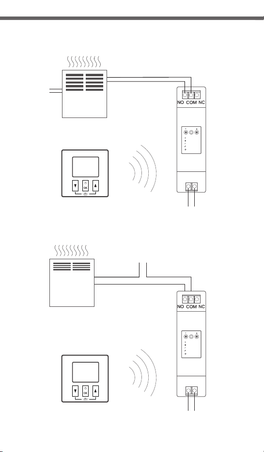
Cooperation of the AURATON RTH receiver with the
AURATON 200 RTH regulator and/or the AURATON T-2 thermometer
Cooperation of the RTH
receiver with a heating device
heating device AURATON RTH
A simplified schematic
of connecting the AURATON RTH
receiver with the heating device
AURATON
200 RTH
Wireless
temperature regulator
Basic configuration of devices
AURATON T-2
Wireless thermometer
(sold separately)
AURATON H-1
Window handle
(sold separately)
AURATON RTH
Receiver connected
to the heating device
Additional system devices

14 15
If, for some reasons, you would like to decrease
temperature in the room, everyday and at the same time, by
3°C, temporary reduction for 6 hours is possible. To do so:
1. Press and hold for 3 seconds both keys.
The moon symbol will be displayed ( ).
2. The controller is switched to the temporary temperature decrease mode
and everyday at the same time will decrease the set temperature in a
normal mode by 3°C for 6 hours.
NOTE: After 6 hours, the controller will return to the main temperature
setting. Instead of the moon symbol ( ), the sun ( ) symbol
will be displayed.
NOTE: The temporary temperature decrease mode always starts when
the function is turned on. This means that the possible temporary
temperature decrease has to be set at the time you want it to take
place.
Setting the temporary
temperature decrease mode
Switching off the temporary temperature
decrease
Press and hold the keys again to switch off the temporary temperature
decrease mode.
The moon ( ) or sun ( ) symbol will disappear and only the room
temperature will be displayed. The controller returns to the normal operating
The operation of temperature regulation in the receiver is based on the
binary algorithm (on/off) using one or two sensor elements.
The AURATON 200 RTH regulator allows for setting and/or monitoring
the temperature.
The AURATON T-2 thermometer provides information about the current
temperature only, without the capability of changing it manually.
A) The manual setpoint – pairing the AURATON 200 RTH regulator with the
RTH receiver allows for setting the temperature manually and controlling
it in the location of the fastening of the 200 RTH regulator.
Cooperation of the AURATON RTH receiver with the
AURATON 200 RTH regulator and/or the AURATON T-2 thermometer
Cooperation of the RTH
receiver with a heating device
heating device AURATON RTH
A simplified schematic
of connecting the AURATON RTH
receiver with the heating device
AURATON
200 RTH
Wireless
temperature regulator
Basic configuration of devices
AURATON T-2
Wireless thermometer
(sold separately)
AURATON H-1
Window handle
(sold separately)
AURATON RTH
Receiver connected
to the heating device
Additional system devices

16
B) The remote setpoint – if the T-2 thermometer is additionally paired with
the RTH receiver, the AURATON 200 RTH regulator retains the capability
of temperature setting, however its control is performed with the paired
T-2 thermometer only. This feature allows for regulating the temperature
in a room other than the one where the AURATON 200 RTH regulator
is placed.
An example: you want the temperature in the “children’s room” to be
always at 22 °C, however you do not want children to be able
to change it - in that room, you install the T-2 thermometer, and the
AURATON 200 RTH regulator in e.g. the kitchen. This way the temperature
in the “children’s room” will always be at 22 °C regardless
of temperature fluctuations in the kitchen.
C) The factory setpoint (20 °C) – if the T-2 thermometer is the only device
paired with the RTH receiver, it is not possible to set the temperature
manually, and the RTH receiver maintains the factory temperature
setpoint of 20 °C.
NOTE!
1. The sequence of pairing the AURATON 200 RTH regulator and the T-2
thermometer is very important. If you want to maintain the remote
setpoint, you must first pair the AURATON 200 RTH with the RTH receiver,
and then the T-2 thermometer. Reversing the pairing sequence will cause
automatic deregistering of the previously paired T-2 thermometer and
entering the mode of operation described in item A.
2. The RTH receiver can operate with one AURATON 200 RTH regulator
and/or one T-2 thermometer only. Pairing a new regulator causes
deregistering the previously paired regulator and the T-2 thermometer.
Pairing a new T-2 thermometer causes deregistering the previously
paired T-2 thermometer only.
3. The 200 RTH regulator and/or the T-2 thermometer can operate with an
unlimited number of receivers, e.g. one regulator can simultaneously
control two independent heating devices.
Cooperation with the AURATON 200 RTH regulator and/or
the AURATON T-2 thermometer as well as the AURATON H-1 handles
By default, the AURATON RTH receiver does not have any AURATON H-1
handle or AURATON W-1 window position sensor paired, therefore the relay
is controlled by the paired AURATON 200 RTH regulator and/or
the AURATON T-2 thermometer. When at least one H-1 handle is paired with
the RTH receiver, the relay is controlled in the following manner:
A) The window is closed or trickle-ventilated (micro-ventilation).
When the H-1 window handles is paired with the receiver, and all
windows are closed or trickle-ventilated, the relay still maintains the
setpoint from the paired AURATON 200 RTH regulator and/or the
T-2 thermometer.
B) The window is pivoted.
If at least one window is pivoted, the temperature set in the AURATON
200 RTH regulator is lowered in AURATON RTH receiver down to 3 °C. This
state will be maintained until closing. This state will last until all windows
are closed or trickle-ventilated.
C) The window is opened.
When you open a window equipped with the H-1 handle paired for
longer than 30 seconds, the relay in the AURATON RTH receiver
is switched off, as is the connected heating device. If all the assigned
windows are again in a state other than “opened”, the RTH receiver
returns to normal cooperation with the AURATON 200 RTH regulator
and/or the T-2 thermometer no earlier than 90 seconds after switching
off the relay. The purpose of this delay is to prevent too rapid transitions of
the connected heating devices between the ON and OFF states. However,
if the temperature in the room drops below 7 °C, the relay inside the
receiver is switched on regardless of the positions of windows in order to
prevent the room from freezing.
D) The signal is lost.
When the RTH receiver has lost the signal from the H-1 handle paired (3
consecutive transmissions are lost), it changes the status if this window to
“closed”. When the transmission is restored, the H-1 handle is again
properly read off by the RTH receiver.

18 19
Special situations
ź
ź
ź
ź
ź
When 3 consecutive transmissions (after 15 minutes) from the AURATON
200 RTH regulator and/or the T-2 thermometer are lost, an error is
signalled on the RTH receiver (LED flashing continuously red and green).
The RTH receiver starts executing the ON - OFF cycle memorised during
the last 24 hours of operation until the problem is removed.
When both signals return (from the AURATON 200 RTH regulator and
the T-2 thermometer), the error is cancelled and the receiver enters its
normal mode of operation.
When only the T-2 thermometer signal returns, the receiver uses the last
memorised setpoint value and maintains it while signalling the error.
When the H-1 handles, the T-2 thermometer and the AURATON 200 RTH
regulator (the temperature is measured with the T-2 thermometer) are
paired with the receiver, then maintaining the work cycle from the last 24
hours occurs only after losing the signal from the T-2 thermometer. When
only the signal from the AURATON 200 RTH is missing, the RTH receiver
automatically maintains the last memorised setpoint from the AURATON
2025 RTH regulator and also signals an error.
When you have only the H-1 handles and the T-2 thermometer paired with
the RTH receiver without the AURATON 200 RTH regulator, the RTH
receiver maintains a constant, factory-defined temperature of 20 °C. If you
pivot any window equipped with the H-1 handle paired with the receiver,
a temperature of 17 °C is maintained. If you open any window equipped
with the H-1 handle paired with the RTH receiver, the receiver switches off
the heating device, but will switch it back on when the temperature falls
below 7 °C.
ź
ź
ź
Switching the relay is synchronised with the wave of the 230 V mains voltage
in order to ensure that closing and opening contacts of the relay occurs
around the zero-crossing point. This prevents the occurrence of an electric
arc, significantly extending the relay service time.
The AURATON RTH receiver is equipped with a unique algorithm for
analysing the ON - OFF cycles. The entire heating cycle from the last 24 hours
is recorded in the memory of the RTH receiver. In the event of losing
communication with the AURATON 200 RTH regulator and/or the T-2
thermometer, the RTH receiver automatically executes the ON - OFF cycle
memorised during the last 24 hours. This provides time for restoring
transmission (removing interferences) or fixing the 200 RTH regulator
and/or the T-2 thermometer without a significant deterioration of thermal
comfort conditions in the controlled spaces.
Cooperation with optional devices (the AURATON T-2 thermometer,
the AURATON H-1 window handle).
Unique features of AURATON 200 RTH
Additional information and notes
ź
ź
ź
ź
ź
źThe controller can be switched on or off at any time by holding the key
pressed for a while.
źPressing any function key for the first time always starts
the backlight first, and then the key function is performed.
źWhile programming any function, if no key is pressed for 10 seconds, this
will be interpreted as pressing the key.
The AURATON 200 RTH regulator and/or the T-2 thermometer must be
installed at least 1 metre from the RTH receiver (too strong a signal from the
transmitters can cause interference).
At least 30 seconds must elapse between switching the relay off and on.
Data transmission from the AURATON 200 RTH regulator to the receiver
occurs upon each change of 0.2 °C of the surrounding temperature. When
the temperature is stable, the regulator sends heart-beat data every 5
minutes (which is signalled with the LED blinking orange on the RTH
receiver).
In the event of a power outage, the RTH receiver will switch off. When power
is restored, the heating device is switched on automatically, and the RTH
receiver awaits a signal from the paired transmitters (this signal should be
received within 5 minutes of restoring power). After receiving the signal, the
RTH receiver enters the normal mode of operation.
The RTH receiver cannot be placed in metal containers (e.g. an assembly
box, a metal enclosure of a heater) in order to not to interfere with its
operation.
20 21
Working temperature range:
Temperature measurement range: 0 – 35°C
Temperature control range: 5 – 30°C
Span: ±0,2°C
Temperature setting accuracy: 0,2°C
Temperature reading accuracy:: ±0,2°C
Default temperature setting: 20°C
Additional function: FrostGuard
Operating cycle: Daily
Working mode control: LED (the RTH receiver) / LCD (the regulator)
Maximum load: AURATON RTH ~ 16A 250V AC
AURATON 200 RTH power supply 2x AAA 1.5V alkaline batteries
RTH power supply: 230V AC, 50Hz
RTH radio frequency: 868MHz
RTH Operation range: in a typical building, with standard construction
of walls - approx. 30 m
an open space - up to 300 m
0 – 45°C
AURATON 200 RTH
AURATON RTH
OFF
ON
IN
OUT
ALARM
RESET
230V AC
~
L N
control
230V
~
power
AURATON 200 RTH
AURATON RTH
OFF
ON
IN
OUT
ALARM
RESET
230V AC
~
L N
L
N
L
Nheating
device
e.g. a gas furnace
electric
heating
device
Max. 230V
~
16 A
Max. 230V
~
Disposing of the devices
The devices are marked with the crossed waste bin symbol. According
to European Directive no. 2002/96/EU and the Act concerning used
up electric and electronic equipment, such a marking indicates that
this equipment may not be placed with other household generated waste.
The user is responsible for delivering the devices to a reception point
for used-up electric and electronic equipment.
Technical specifications
The AURATON RTH receiver connection schematics
Table of contents
Other AURATON Thermostat manuals

AURATON
AURATON Tucana User manual

AURATON
AURATON Auriga User manual

AURATON
AURATON 2005 TX User manual

AURATON
AURATON Libra User manual

AURATON
AURATON S03 RTH User manual

AURATON
AURATON R30 RT User manual

AURATON
AURATON 2005 User manual

AURATON
AURATON 1300 User manual

AURATON
AURATON 2100 TX User manual

AURATON
AURATON 2020 User manual


Popular Thermostat manuals by other brands


Honeywell
Honeywell Digital Round T8775A installation manual

SwannOne
SwannOne ZEN-01 quick start guide

Jackson Systems
Jackson Systems T-32-TS Touchscreen Thermostat user manual

White Rodgers
White Rodgers 1E65-144 Installation and operation instructions

LUX
LUX DMH110b Installation and operating instructions

Uponor
Uponor Base flexiboard X-24 230V manual