ADS-RR(SR)-MUS01-DS-IG-EN maestro.idatalink.com
Ford Mustang Base 2010-2012
Automotive Data Solutions Inc. © 2019 4
INSTALLATION INSTRUCTIONS
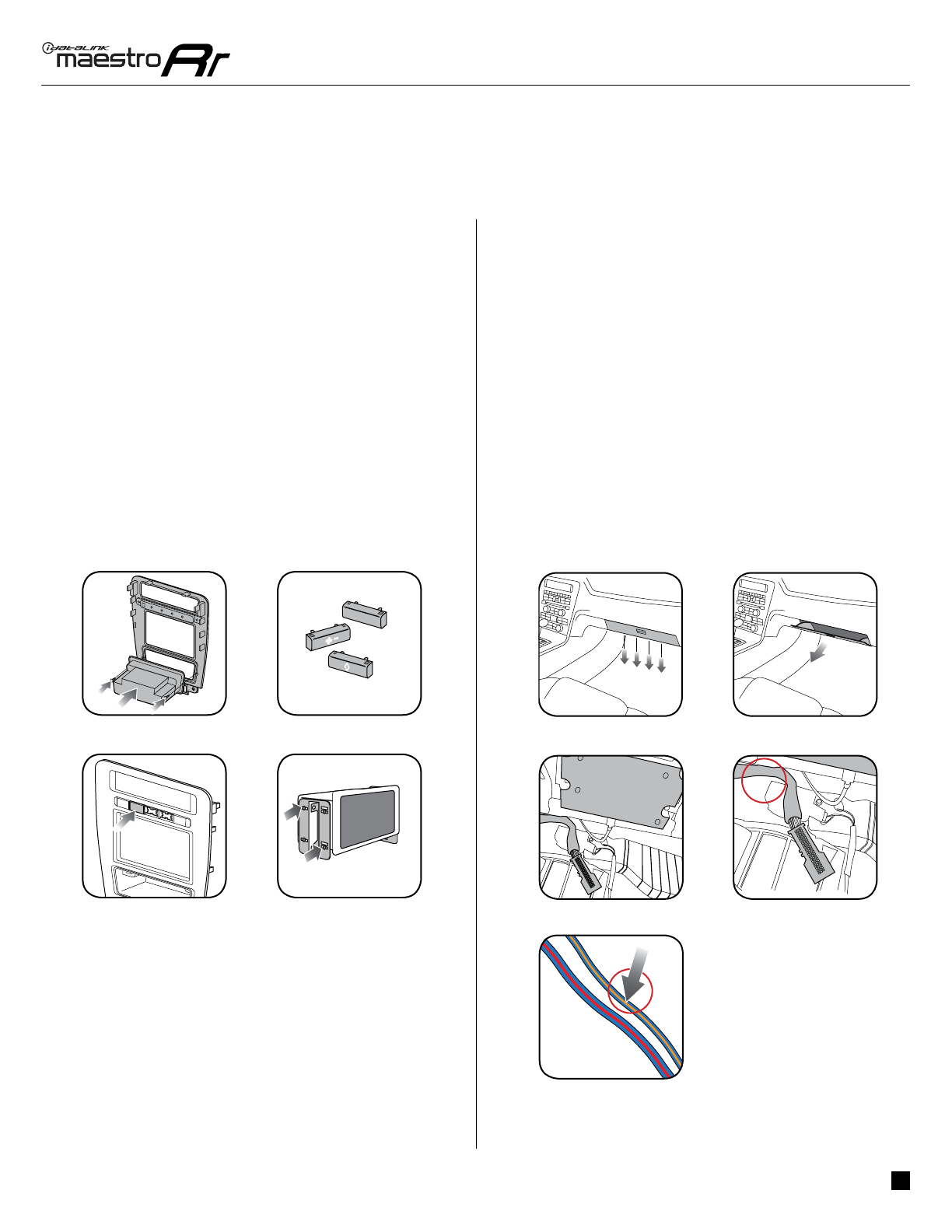
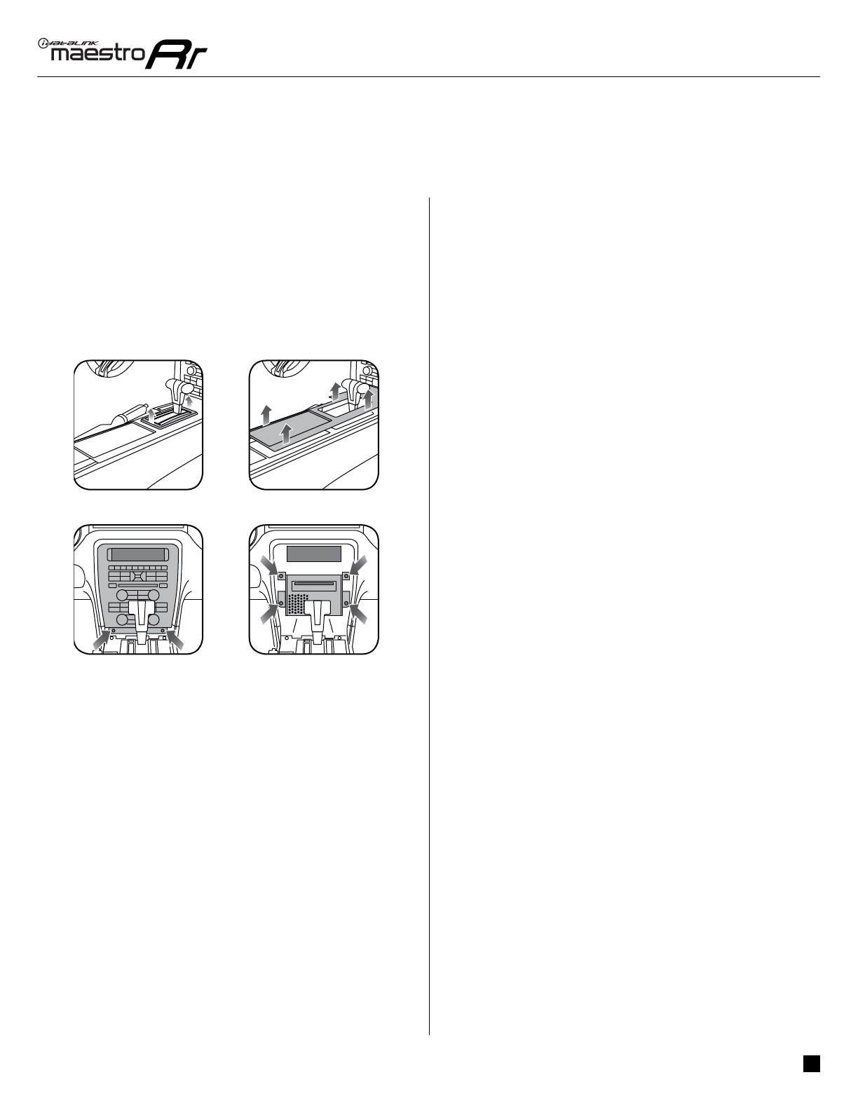
STEP 3
• Remove the shifter cover then remove the central console
cover carefully. (3.1, 3.2)
• Unscrew and remove the original radio panel. The plug
from this panel will not be reused. (3.3)
• Disconnect the factory radio and keep its factory harness
accessible for later use. (3.4)
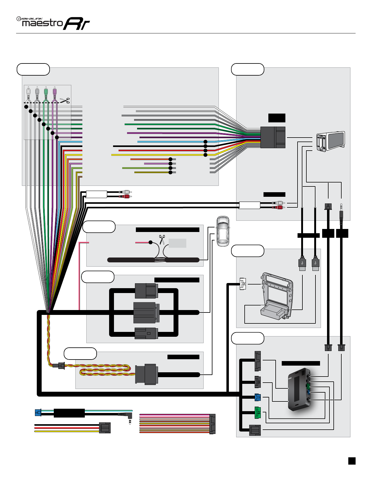
STEP 4
• Cut the WHITE, GRAY, GREEN and PURPLE RCA tips.
Connect every wire to the aftermarket radio main harness
and match the wire colors.
• Connect every wire from the aftermarket radio main
harness to the MUS1 T-harness and match the wire colors.
(Refer to Diagram)
STEP 5
(with SYNC only)
• Cut the SWI 2 INPUT wire.
• Connect the PINK/RED wire of MUS1 T-harness to the SWI
2 INPUT wire going to the steering wheel. Insulate the wire
side going to the SYNC module and plug the SYNC harness
into the SYNC module.
STEP 6
• Connect the factory harness to the MUS1 T-harness.
Connect only the available connectors. For example, if the
factory harness has two connectors, connect only these
two connectors.
STEP 7
• Plug the OBDII connector into the OBDII of the vehicle,
under the driver side dash.
STEP 8
• Plug the aftermarket radio harnesses into the aftermarket
radio.
• Plug the Data cable to the data port of the aftermarket
radio.
• Insert the Audio cable into the iDatalink 3.5 mm audio
jack of the aftermarket radio (If there is no iDatalink audio
input, connect to AUX).
Note: On Pioneer radio, ensure that there is nothing
plugged into the W/R port.
• Insert the RCA connectors into the aftermarket radio.
NOTES:
The RCA connectors labeled SUB IN can be used to feed
the subwoofer channel of the factory amplifi er. The RCA
connectors labeled AUX IN can be used to connect the
factory 3.5 mm audio jack, in vehicles that are NOT equipped
with SYNC, to the auxiliary input of the aftermarket radio.
STEP 9
• Secure the aftermarket radio in the dashboardhousing.
• Connect all the harnesses to the Maestro RR module.
STEP 10
• Connect all the harnesses to the MUS1 radio panel.
Fig. 3.2
4


-TL2 User manual")