tau ARM200 Series User manual

1
MANUALE D’USO E MANUTENZIONE
USE AND MAINTENANCE MANUAL
BEDIENUNGS - UND WARTUNGSANLEITUNG
MANUEL D’EMPLOI ET D’ENTRETIEN
MANUAL DE USO Y MANTENIMIENTO
MANUAL DO UTILIZADOR E MANUTENÇÃO
ARM200
Series
D_MNL0ARM200 17-09-2019 - Rev.30
IT - Istruzioni originali

2
A
B
122,5
C
99
g. 1
g. 2
g. 3
1
2
6
5
3
4
ARM A B max C max
225I - 225BI 290 mm 1070 mm 1098 mm
250I - 250BI
250BR 425 mm 1350 mm 1378 mm
270I - 270BI 530 mm 1560 mm 1588 mm
290BI 853 mm 2266 mm 2294 mm
1
a
2
74
4
1
ab
f
c
c
d
d
e
7
3
7
3
5
6
ARM200 ARM200BI / BR
a 4x1,5 mm² 2x2,5 mm² + 3x0,5 mm²
b 3x1,5 mm² 3x1,5 mm²
c 2x0,5 mm² 2x0,5 mm²
d 4x0,5 mm² 4x0,5 mm²
e 3x0,5 mm² 3x0,5 mm²
f 2x1 mm² + 1RG58 2x1 mm² + 1RG58
ARM200 Series
3
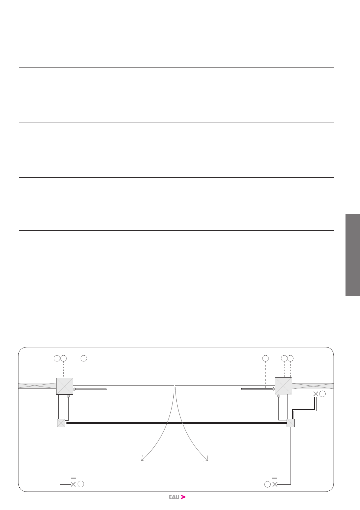
PREDISPOSIZIONI OPERE MURARIE (g. 4)
1) Attuatore 5) Fotocellule a parete
2) Centralina 6) Battenti
3) Selettore a chiave 7) Fotucellule a colonnina
4) Antenna e lampeggiante 8) Elettroserratura
PREPARAÇÃO DE OBRAS DE ALVENARIA (g.4 )
1) Motoredutor 5) Fotocélulas na parede
2) Unidade de controle 6) folhas
Seletor de teclas 7) Fotucélula de coluna
4) Antena e piscando 8) Fechadura elétrica
ARRANGEMENT OF WALL INTERVENTIONS (g.4
1) Actuator 5) Wall-mounted photocells
2) Control unit 6) Gate stops
3) Key switch 7) Photocells on post
4) Aerial and ashing light 8) Electric lock
VORBEREITUNG VON WANDARBEITEN (Abb. 4)
1) Antrieb 5) Photozellen an Mauer
2) Steuerzentrale 6) Anschläge
3) Schlüsselschalter 7) Photozellen auf Ständer
4) Antenne und Blinkleuchte 8) Elektroschloss
PRÉPARATION DE TRAVAUX DE CONSTRUCTION (g. 4)
1) Opérateur 5) Photocellules murales
2) Logique de commande 6) Battants
3) Sélecteur a clé 7) Photocellules sur colonne
4) Antenne et clignotant 8) Serrure électrique
PREPARACIÓN OBRAS DE ALBAÑILERÍA (g. 4)
1) Operador 5) Fotocélulas de pared
2) Centralita 6) Topes
3) Selector de llave 7) Fotocélulas en columnas
4) Antena y luz intermitente 8) Electrocerradura
M1
M2
2 x Ø 40 mm
1 x Ø 80 mm
≥ 200 x 200 mm
2 x Ø 32 mm
1 x Ø 32 mm
2 x Ø 32 mm
1 x Ø 32 mm
1 x Ø 32 mm
1 x Ø 32 mm
≥ 200 x 200 mm
3 5 5
2
7
7
41 1
g. 4
ARM200 Series

4
A
C
X°
B
L
Y°
Y°
g. 5
TYPE L
ARM225I
ARM225BI 1070 mm
ARM250I
ARM250BI
ARM250BR
1350 mm
ARM270I
ARM270BI 1560 mm
ARM290BI 2266 mm
QUOTE DI
INSTALLAZIONE
(FIG.4)
INSTALLATION
DIMENSIONS
(FIG.4)
ANBAUMASSE
(ABB.4)
COTES
D’INSTALLATION
(FIG.4)
COTAS DE
INSTALACIÓN
(FIG.4)
COTAS PARA
INSTALAÇÃO
(FIG.4)
Determinare la posizione di montaggio dell’attuatore facendo ri-
ferimento alla g.5.
Vericare attentamente che la distanza tra l’anta aperta ed even-
tuali ostacoli (pareti, recinzioni etc.) sia superiore all’ingombro
dell’attuatore.
Determine the tting position of the actuator with reference to
g.5.
Check with care if the distance between the open leaf and any ob-
stacles (walls, fences etc.) is higher than the actuator dimensions.
Die Montageposition des Antriebs bestimmen und hierzu Bezug
auf die Abbildung 5 nehmen.
Aufmerksam sicherstellen, dass der Abstand zwischen dem oe-
nen Flügel und eventuellen Hindernissen (Wände, Umzäunungen
usw.) über dem Platzbedarf des Antriebs liegt.
Déterminer la position de montage de l’opérateur en se reportant
à la g.5.
Vérier attentivement que la distance entre le vantail ouvert et les
obstacles éventuels (murs, clôtures etc.) est supérieure à l’encom-
brement de l’opérateur.
Establezca la posición de montaje del accionador tomando como
referencia la g.5.
Compruebe atentamente que la distancia entre la hoja abierta y
los posibles obstáculos (paredes, vallas, etc.) sea superior al espa-
cio ocupado por el operador.
Determine a posição adequada do atuador / braço com base na
g. 5.
Verique cuidadosamente se a distância entre a folha de abertura
e quaisquer obstáculos (paredes, cercas, etç.) é superior ao espa-
ço ocupado pelo atuador / braço.
ARM225 ARM250
X° A (mm) B (mm) C (mm) X° A (mm) B (mm) C (mm)
90 110 120 ÷ 165 20 mm 90 120 ÷ 125 135 ÷ 275 20 mm
90 115 120 ÷ 160 20 mm 90 130 135 ÷ 270 20 mm
90 120 ÷ 125 120 ÷ 155 20 mm 90 135 135 ÷ 265 20 mm
90 130 120 ÷ 150 20 mm 90 140 135 ÷ 260 20 mm
90 135 120 ÷ 145 20 mm 90 145 ÷ 150 135 ÷ 255 20 mm
90 140 120 ÷ 140 20 mm 90 155 135 ÷ 250 20 mm
90 145 120 ÷ 135 20 mm 90 160 135 ÷ 245 20 mm
90 150 ÷ 155 120 ÷ 130 20 mm 90 165 135 ÷ 240 20 mm
90 160 120 ÷ 125 20 mm 90 170 ÷ 175 135 ÷ 235 20 mm
90 165 120 ÷ 120 20 mm 90 180 135 ÷ 230 20 mm
100 130 120 ÷ 130 20 mm 90 185 135 ÷ 225 20 mm
100 135 120 ÷ 120 20 mm 90 190 ÷ 195 135 ÷ 220 20 mm
90 200 135 ÷ 215 20 mm
100 145 135 ÷ 160 20 mm
100 150 135 ÷ 210 20 mm
100 155 135 ÷ 225 20 mm
100 160 135 ÷ 220 20 mm
100 165 135 ÷ 215 20 mm
100 170 135 ÷ 210 20 mm
100 170 135 ÷ 205 20 mm
100 180 135 ÷ 200 20 mm
100 185 135 ÷ 195 20 mm
ARM200 Series

5
INSIDE
OUTSIDE
C
A
B D
E
F
G
QUOTE DI
INSTALLAZIONE
PER MONTAGGIO
SU ANTE CON
APERTURA VERSO
L’ESTERNO
SIZES TO
INSTALL THE
OPERATOR
ON OUTDOOR
OPENING
LEAVES
EMPLACEMENT
POUR L’INSTALLA-
TION DU MOTEUR
SUR VANTAUX
OUVRANT VERS
L’EXTÉRIEUR
INSTALLA-
TIONSMAßE
FÜR DIE MONTA-
GE AUF FLüGEL
MIT ÖFFNUNG
NACH AUßEN
MEDIDAS DE
INSTALACIÓN
PARA MONTAJE
EN HOJAS CON
APERTURA HA-
CIA EL EXTERIOR
MEDIDAS DE
INSTALAÇÃO
PARA MONTA-
GEM DE PORTAS
COM ABERTURA
PARA FORA
ARM270 ARM290
X° A (mm) B (mm) C (mm) X° A (mm) B (mm) C (mm)
90 150 170 ÷ 345 20 mm 90° 200 225 – 595 20
90 155 170 ÷ 340 20 mm 90° 210 225 – 585 20
90 160 ÷ 165 170 ÷ 335 20 mm 90° 220 225 – 580 20
90 170 170 ÷ 330 20 mm 90° 230 225 – 570 20
90 175 ÷ 180 170 ÷ 325 20 mm 90° 240 225 – 565 20
90 185 170 ÷ 320 20 mm 90° 250 225 – 555 20
90 190 170 ÷ 315 20 mm 90° 260 225 – 550 20
90 195 170 ÷ 310 20 mm 90° 270 225 – 545 20
90 200 ÷ 205 170 ÷ 305 20 mm 90° 280 225 – 535 20
90 210 170 ÷ 300 20 mm 90° 290 225 – 530 20
90 215 170 ÷ 295 20 mm 90° 300 225 – 520 20
90 220 ÷ 225 170 ÷ 290 20 mm 90° 310 225 – 515 20
100 175 170 ÷ 170 20 mm 90° 320 225 – 505 20
100 180 170 ÷ 220 20 mm 90° 330 225 – 500 20
100 185 170 ÷ 280 20 mm 90° 340 225 – 495 20
100 190 170 ÷ 285 20 mm 90° 350 225 – 490 20
100 195 170 ÷ 280 20 mm 90° 360 225 – 485 20
100 200 170 ÷ 275 20 mm 90° 370 225 – 475 20
100 205 170 ÷ 270 20 mm 90° 380 225 – 470 20
100 210 170 ÷ 265 20 mm 90° 390 225 – 460 20
100 215 170 ÷ 260 20 mm 90° 400 225 – 455 20
100 220 170 ÷ 255 20 mm 90° 410 225 – 450 20
100 225 170 ÷ 250 20 mm 90° 420 225 – 445 20
110 210 170 ÷ 175 20 mm 90° 430 225 – 435 20
110 215 170 ÷ 190 20 mm 90° 440 225 – 430 20
110 220 170 ÷ 210 20 mm 90° 450 225 – 420 20
110 225 170 ÷ 225 20 mm 100° 230 225 – 245 20
100° 250 225 – 480 20
100° 300 225 – 470 20
100° 350 225 – 430 20
100° 400 225 – 385 20
100° 450 225 – 345 20
125° 370 225 – 240 20
125° 400 225 – 265 20
125° 420 225 – 235 20
g. 5B
TYPE A B C D E F G
ARM225I - ARM225BI 125 mm 145 mm 3,3° 781 mm 925 mm 60 mm 40 mm
ARM250I - ARM250BI - ARM250BR 130 mm 145 mm 3,1° 931 mm 1075 mm 60 mm 40 mm
ARM270I - ARM270BI 155 mm 180 mm 4,2° 1032 mm 1210 mm 60 mm 40 mm
Example mounting: Opening
outwards
Esempio di montaggio per
apertura anta verso l’esterno.
ARM200 Series

6
g. 7
g. 9
O
R
12
g. 8 g. 8A
1
g. 10 g. 11
g. 6
g. 6A
g. 6B
ARM200 Series

7
Negativo encoder
Encoder negative
Minuspol Encoder
Négatif encoder
Negativo encoder
Negativo encoder
Positivo encoder
Encoder positive
Pluspol Encoder
Positif encoder
Positivo encoder
Positivo encoder
Segnale encoder
Encoder signal
Encodersignal
Signal encodeur
Señal encoder
Sinal encoder
Negativo motore
Motor negative
Minuspol Motor
Négatif moteur
Negativo motor
Negativo motor
Positivo motore
Motor Positive
Pluspol Motor
Positif moteur
Positivo motor
Positivo motor
Comune
Common
Gemeinsam
Commune
Común
Comum
Chiude
Close
Zu
Ferme
Cierra
Fecha
Apre
Open
Auf
Ouvre
Abre
Abre
6,3 mm
g. 12 g. 13
g. 14
g. 15 g. 16
g. 17 g. 18 g. 19
ARM200 Series

8
Os dados descritos neste manual são puramente indicativos. A TAU reserva-se no direito de o modicar a qualquer momento.
O fabricante reserva-se no direito de modicar ou actualizar o produto sem aviso prévio. Possíveis imprecisões ou erros neste
manual serão corrigidos na próxima edição / revisão.
Ao abrir a embalagem certique-se que o produto está intacto. Recicle os materiais segundo as normas em vigor.
Este producto só pode ser instalado por um técnico qualicado. O fabricante TAU declina qualquer responsabilidade por
danos pessoais ou materiais resultantes de uma instalação incorrecta do equipamento ou a sua não conformidade com
a norma vigente (Ver Directiva de Máquinas).
I dati riportati nel presente manuale sono puramente indicativi. La TAU si riserva il diritto di modicarli in qualsiasi momento.
La Casa costruttrice si riserva il diritto di apportare modiche o miglioramenti al prodotto senza alcun preavviso. Eventuali im-
precisioni o errori riscontrabili nel presente fascicolo, saranno corretti nella prossima edizione.
All’apertura dell’imballo vericare che il prodotto sia integro. Riciclare i materiali secondo la normativa vigente.
L’installazione del prodotto dovrà essere eettuata da personale qualicato. La Ditta costruttrice Tau declina ogni re-
sponsabilità per danni derivanti a cose e/o persone dovuti ad un’eventuale errata installazione dell’impianto o la non
messa a Norma dello stesso secondo le vigenti Leggi (vedi Direttiva Macchine).
Los datos describidos en este manual son puramente indicativos. La TAU se reserva el derecho de modicarlos en cualquier
momento.
El Fabricante se reserva el derecho de modicar o actualizar el producto sin aviso previo. Posibles imprecisiones o errores en
este manual serán corregidos en la próxima edición.
Cuando abra el embalaje, controle que el producto esté íntegro. Recicle los materiales según la normativa vigente.
La instalación del producto tiene que ser efectuada por personal cualicado. El Fabricante Tau no se asume ninguna
responsabilidad por lesiones a personas o averías a cosas causadas por una instalación incorrecta del equipo o la por la
inobservancia de la normativa vigente (véase Directiva de Máquinas).
The data described in this handbook are purely a guide. TAU reserves the right to change them in any moment.
The manufacturer reserves the right to modify or improve products without prior notice. Any inaccuracies or errors found in this
handbook will be corrected in the next edition.
When opening the packing please check that the product is intact. Please recycle materials in compliance with current regula-
tions.
This product may only be installed by a qualied tter. The manufacturer declines all liability for damage to property
and/or personal injury deriving from the incorrect installation of the system or its non-compliance with current law (see
Machinery Directive).
Les données décrites dans ce manual sont purement indicatives. La TAU se réserve le droit de les modier à n’importe quel
moment.
Le Constructeur se réserve le droit d’apporter des modications ou des améliorations au produit sans aucun préavis. Les éven-
tuelles imprécisions ou erreurs présentes dans ce fascicule seront corrigées dans la prochaine édition.
À l’ouverture de l’emballage, vérier que le produit est intact. Recycler les matériaux suivant les normes en vigueur.
L’installation du produit devra être eectuée par du personnel qualié. Tau décline toute responsabilité pour les dom-
mages aux choses et/ou personnes dus à une éventuelle installation erronée de l’automatisme ou à la non-mise aux
normes suivant les lois en vigueur (voir Directive Machines).
Die beschriebenen Daten in der vorliegenden Betriebsanleitung sind rein indikativ. TAU behält sich vor, diese in jedem Moment
zu modizieren.
Der Hersteller behält sich das Recht vor, ohne vorherige Benachrichtung Änderungen oder Verbesserungen am Produkt anzu-
bringen. Ungenauigkeiten oder Fehler, die in der vorliegenden Ausgabe festgestellt werden, werden in der nächsten Ausgabe
berichtigt.
Beim Önen der Verpackung prüfen, dass das Produkt keine Schäden aufweist. Die Materialien nach den gültigen Vorschriften
recyclen.
Die Installation des Produktes muss von Fachpersonal ausgeführt werden. Die Herstellerrma TAU übernimmt keinerlei
Haftung für Personen- und/oder Sachschäden aufgrund einer falschen Installation der Anlage oder der Nichtkonformi-
tät derselben mit den gültigen Gesetzen (siehe Maschinenrichtlinie).
Italiano
Español
Português
English
Français
Deutsch
ARM200 Series

9
AVVERTENZE PER L’INSTALLATORE - OBBLIGHI GENERALI PER LA SICUREZZA
A) Leggere attentamente le istruzioni prima di procedere all’installazione, in quanto forniscono importanti indicazioni concernenti
la sicurezza, l’installazione, l’uso e la manutenzione. Una errata installazione o un errato uso del prodotto può portare a gravi
danni alle persone.
B) I materiali dell’imballaggio (plastica, polistirolo, ecc.) non devono essere lasciati alla portata dei bambini in quanto potenziali fonti di pe-
ricolo.
C) Conservare le istruzioni per riferimenti futuri.
D) Questo prodotto è stato progettato e costruito esclusivamente per l’utilizzo indicato in questa documentazione. Qualsiasi altro utilizzo
non espressamente indicato potrebbe pregiudicare l’integrità del prodotto e/o rappresentare fonte di pericolo.
E) TAU declina qualsiasi responsabilità derivata dall’uso improprio o diverso da quello per cui l’automatismo è destinato.
F) Non installare il prodotto in ambiente e atmosfera esplosivi.
G) Gli elementi costruttivi meccanici devono essere in accordo con quanto stabilito dalle Norme EN 12604 e EN 12605. Per i Paesi extra-CEE,
oltre ai riferimenti normativi nazionali, per ottenere un livello di sicurezza adeguato, devono essere seguite le Norme sopra riportate.
H) TAU non è responsabile dell’inosservanza della Buona Tecnica nella costruzione delle chiusure da motorizzare, nonché delle deformazio-
ni che dovessero intervenire nell’utilizzo.
I) L’installazione deve essere eettuata nell’osservanza delle Norme EN 12453 e EN 12445. Il livello di sicurezza dell’automazione deve es-
sere C+D.
J) Prima di eettuare qualsiasi intervento sull’impianto, togliere l’alimentazione elettrica e scollegare le batterie.
K) Prevedere sulla rete di alimentazione dell’automazione un interruttore onnipolare con distanza d’apertura dei contatti uguale o superiore
a 3 mm. È consigliabile l’uso di un magnetotermico da 6A con interruzione onnipolare.
L) Vericare che a monte dell’impianto vi sia un interruttore dierenziale con soglia da 0,03 A.
M) Vericare che l’impianto di terra sia realizzato a regola d’arte e collegarvi le parti metalliche della chiusura.
N) L’automazione dispone di una sicurezza intrinseca antischiacciamento costituita da un controllo di coppia. E’ comunque necessario veri-
carne la soglia di intervento secondo quanto previsto dalle Norme indicate al punto I.
O) I dispositivi di sicurezza (norma EN 12978) permettono di proteggere eventuali aree di pericolo da Rischi meccanici di movimento, come
ad Es. schiacciamento, convogliamento, cesoiamento.
P) Per ogni impianto è consigliato l’utilizzo di almeno una segnalazione luminosa nonché di un cartello di segnalazione ssato adeguata-
mente sulla struttura dell’insso, oltre ai dispositivi citati al punto O.
Q) Il costruttore dell’automazione declina ogni responsabilità qualora vengano installati componenti incompatibili ai ni della sicurezza e del
buon funzionamento. Per l’eventuale riparazione o sostituzione dei prodotti dovranno essere utilizzati esclusivamente ricambi originali.
R) Per la manutenzione utilizzare esclusivamente parti originali TAU.
S) Non eseguire alcuna modica sui componenti facenti parte del sistema d’automazione.
T) L’installatore deve fornire tutte le informazioni relative al funzionamento manuale del sistema in caso di emergenza e consegnare all’U-
tente utilizzatore dell’impianto la “Guida Utente” allegata al prodotto.
U) Non permettere ai bambini o persone di sostare nelle vicinanze del prodotto durante il funzionamento.
W) Tenere fuori dalla portata dei bambini radiocomandi o qualsiasi altro datore di impulso, per evitare che l’automazione possa essere azio-
nata involontariamente.
X) Il transito tra le ante deve avvenire solo a cancello completamente aperto.
Y) L’Utente utilizzatore deve astenersi da qualsiasi tentativo di riparazione o d’intervento diretto e rivolgersi solo a personale qualicato.
Z) Tutto quello che non è previsto espressamente in queste istruzioni non è permesso.
Consigliamo di riporre tutta la documentazione relativa all’impianto all’interno o nelle immediate vicinanze della centralina.
Italiano
IMPORTANT NOTICE FOR THE INSTALLER - GENERAL SAFETY REGULATIONS
A) Please read these instructions carefully before installing the product as they contain important information concerning safety,
installation, use and maintenance. Incorrect installation or incorrect use of the product could cause serious harm to people.
B) Do not leave packing materials (plastic, polystyrene, etc.) within reach of children as such materials are potential sources of danger.
C) Store these instructions for future reference.
D) This product was designed and built strictly for the use indicated in this documentation. Any other use, not expressly indicated here,
could compromise the good condition/operation of the product and/or be a source of danger.
E) TAU declines all liability caused by improper use or use other than that for which the automated system was intended.
F) Do not install the product in explosive environments.
G) The mechanical parts must conform to the provisions of Standards EN 12604 and EN 12605. For non-EU countries, to obtain an adequate
level of safety, the Standards mentioned above must be observed, in addition to national legal regulations.
H) TAU is not responsible for failure to observe Good Technique in the construction of the closing elements to be motorised, or for any
deformation that may occur during use.
I) The installation must conform to Standards EN 12453 and EN 12445. The safety level of the automated system must be C+D.
J) Before attempting any job on the system, cut out electrical power and disconnect the batteries.
K) The mains power supply of the automated system must be tted with an all-pole switch with contact opening distance of 3mm or greater.
Use of a 6A thermal breaker with all-pole circuit break is recommended.
L) Make sure that a dierential switch with threshold of 0.03 A is tted upstream of the system.
M) Make sure that the earthing system is perfectly constructed, and connect metal parts of the means of the closure to it.
N) The automated system is supplied with an intrinsic anti-crushing safety device consisting of a torque control. Nevertheless, its tripping
threshold must be checked as specied in the Standards indicated at point “I”.
O) The safety devices (EN 12978 standard) protect any danger areas against mechanical movement Risks, such as crushing, dragging, and
shearing.
P) Use of at least one indicator-light is recommended for every system, as well as a warning sign adequately secured to the frame structure,
in addition to the devices mentioned at point “O”.
Q) The manufacturer declines all liability if incompatible safety and components are installed. Only use original spare parts to repair or
replace the product.
R) For maintenance, strictly use original parts by TAU.
S) Do not in any way modify the components of the automated system.
T) The installer shall supply all information concerning manual operation of the system in case of an emergency, and shall hand over to the
user the “User Guide” supplied with the product.
U) Do not allow children or adults to stay near the product while it is operating.
W) Keep remote controls or other pulse generators away from children, to prevent the automated system from being activated involuntarily.
X) Transit through the leaves is allowed only when the gate is fully open.
Y) The user must not attempt any kind of repair or direct action whatever and contact qualied personnel only.
Z) Anything not expressly specied in these instructions is not permitted.
Keep all the documents concerning the system inside or near the central control unit.
English
ARM200 Series

10
CONSIGNES POUR L’INSTALLATEUR - RÈGLES DE SÉCURITÉ
A) Lire attentivement les instructions avant de procéder à l’installation, dans la mesure où elles fournissent des indications importantes concer-
nant la sécurité, l’installation, l’emploi et la maintenance. Une installation erronée ou un usage erroné du produit peut entraîner de graves
conséquences pour les personnes.
B) Les matériaux d’emballage (matière plastique, polystyrène, etc.) ne doivent pas être laissés à la portée des enfants car ils constituent des sources poten-
tielles de danger.
C) Conserver les instructions pour les références futures.
D) Ce produit a été conçu et construit exclusivement pour l’usage indiqué dans cette documentation. Toute autre utilisation non expressément indiquée pour-
rait compromettre l’intégrité du produit et/ou représenter une source de danger.
E) TAU décline toute responsabilité qui dériverait d’usage impropre ou diérent de celui auquel l’automatisme est destiné.
F) Ne pas installer le produit dans un environnement et une atmosphère explosifs.
G) Les composants mécaniques doivent répondre aux prescriptions des Normes EN 12604 et EN 12605. Pour les Pays extra-CEE, l’obtention d’un niveau de
sécurité approprié exige non seulement le respect des normes nationales, mais également le respect des Normes susmentionnées.
H) TAU n’est pas responsable du non-respect de la Bonne Technique dans la construction des fermetures à motoriser, ni des déformations qui pourraient
intervenir lors de l’utilisation.
I) L’installation doit être eectuée conformément aux Normes EN 12453 et EN 12445. Le niveau de sécurité de l’automatisme doit être C+D.
J) Couper l’alimentation électrique et déconnecter la batterie avant toute intervention sur l’installation.
K) Prévoir, sur le secteur d’alimentation de l’automatisme, un interrupteur omnipolaire avec une distance d’ouverture des contacts égale ou supérieure à 3
mm. On recommande d’utiliser un magnétothermique de 6A avec interruption omnipolaire.
L) Vérier qu’il y ait, en amont de l’installation, un interrupteur diérentiel avec un seuil de 0,03 A.
M) Vérier que la mise à terre est réalisée selon les règles de l’art et y connecter les pièces métalliques de la fermeture.
N) L’automatisme dispose d’une sécurité intrinsèque anti-écrasement, formée d’un contrôle du couple. Il est toutefois nécessaire d’en vérier le seuil d’inter-
vention suivant les prescriptions des Normes indiquées au point “I”.
O) Les dispositifs de sécurité (norme EN 12978) permettent de protéger des zones éventuellement dangereuses contre les Risques mécaniques du mouve-
ment, comme l’écrasement, l’acheminement, le cisaillement.
P) On recommande que toute installation soit doté au moins d’une signalisation lumineuse, d’un panneau de signalisation xé, de manière appropriée, sur la
structure de la fermeture, ainsi que des dispositifs cités au point “O”.
Q) Le constructeur de l’automatisme décline toute responsabilité en cas d’installation de composants incompatibles en matière de sécurité et de bon fonction-
nement. Pour toute réparation ou pour tout remplacement des produits, il faudra utiliser exclusivement des pièces de rechange originales.
R) Utiliser exclusivement, pour l’entretien, des pièces TAU originales.
S) Ne jamais modier les composants faisant partie du système d’automatisme.
T) L’installateur doit fournir toutes les informations relatives au fonctionnement manuel du système en cas d’urgence et remettre à l’Usager qui utilise l’instal-
lation le “Guide Usager” fournie avec le produit.
U) Interdire aux enfants ou aux tiers de stationner près du produit durant le fonctionnement.
W) Eloigner de la portée des enfants les radiocommandes ou tout autre générateur d’impulsions, pour éviter tout actionnement involontaire de l’automatisme.
X) Le transit entre les vantaux ne doit avoir lieu que lorsque le portail est complètement ouvert.
Y) L’Usager qui utilise l’installation doit éviter toute tentative de réparation ou d’intervention directe et s’adresser uniquement à un personnel qualié.
Z) Tout ce qui n’est pas prévu expressément dans ces instructions est interdit.
Nous conseillons de conserver toute la documentation relative à l’installation à l’intérieur de l’armoire de commande ou à proximité immédiate.
HINWEISE FÜR DEN INSTALLATIONSTECHNIKER - ALLGEMEINE SICHERHEITSVORSCHRIFTEN
A) Die Anweisungen vor der Installation genau lesen, da sie wichtige Hinweise mit Bezug auf Sicherheit, Installation, Bedienung und Wartung liefern.
Eine falsche Installation oder ein fehlerhafter Betrieb des Produktes können zu schwerwiegenden Personenschäden führen.
B) Das Verpackungsmaterial (Kunststo, Styropor, usw.) sollte nicht in Reichweite von Kindern aufbewahrt werden, da es eine potentielle Gefahrenquelle dar-
stellt.
C) Die Anleitung sollte aufbewahrt werden, um auch in Zukunft Bezug auf sie nehmen zu können.
D) Dieses Produkt wurde ausschließlich für den in diesen Unterlagen angegebenen Gebrauch entwickelt und hergestellt. Jeder andere Gebrauch, der nicht aus-
drücklich angegeben ist, könnte die Unversehrtheit des Produktes beeinträchtigen und/oder eine Gefahrenquelle darstellen.
E) Die Firma TAU lehnt jede Haftung für Schäden, die durch unsachgemäßen oder nicht bestimmungsgemäßen Gebrauch der Automatik verursacht werden, ab.
F) Das Produkt nicht in EX-Umgebung bzw. EX-Atmosphäre installieren.
G) Die mechanischen Bauelemente müssen den Anforderungen der Normen EN 12604 und EN 12605 entsprechen. Für Länder, die nicht der Europäischen Union
angehören, sind für die Gewährleistung eines entsprechenden Sicherheitsniveaus neben den nationalen gesetzlichen Bezugsvorschriften die oben aufgeführ-
ten Normen zu beachten.
H) Die Firma TAU übernimmt keine Haftung im Falle von nicht fachgerechten Ausführungen bei der Herstellung der anzutreibenden Schließvorrichtungen sowie
bei Deformationen, die eventuell beim Betrieb entstehen.
I) Die Installation muß unter Beachtung der Normen EN 12453 und EN 12445 erfolgen. Die Sicherheitsstufe der Automatik sollte C+D sein.
J) Vor der Ausführung jeglicher Eingrie auf der Anlage sind die elektrische Versorgung und die Batterie abzunehmen.
K) Auf dem Versorgungsnetz der Automatik ist ein omnipolarer Schalter mit Önungsabstand der Kontakte von über oder gleich 3 mm einzubauen. Darüber
hinaus wird der Einsatz eines Magnetschutzschalters mit 6A mit omnipolarer Abschaltung empfohlen.
L) Es sollte überprüft werden, ob vor der Anlage ein Dierentialschalter mit einer Auslöseschwelle von 0,03 A zwischengeschaltet ist.
M) Es sollte überprüft werden, ob die Erdungsanlage fachgerecht ausgeführt wurde. Die Metallteile der Schließung sollten an diese Anlage angeschlossen werden.
N) Die Automation verfügt über eine eingebaute Sicherheitsvorrichtung für den Quetschschutz, die aus einer Drehmomentkontrolle besteht. Es ist in jedem Falle
erforderlich, deren Eingrisschwelle gemäß der Vorgaben der unter Punkt “I” angegebenen Vorschriften zu überprüfen.
O) Die Sicherheitsvorrichtungen (Norm EN 12978) ermöglichen den Schutz eventueller Gefahrenbereiche vor mechanischen Bewegungsrisiken, wie zum Beispiel
Quetschungen, Mitschleifen oder Schnittverletzungen.
P) Für jede Anlage wird der Einsatz von mindestens einem Leuchtsignal empfohlen sowie eines Hinweisschildes, das über eine entsprechende Befestigung mit
dem Aufbau des Tors verbunden wird. Darüber hinaus sind die unter Punkt ”O” erwähnten Vorrichtungen einzusetzen.
Q) Der Hersteller der Automatisierung übernimmt keinerlei Haftung, falls Bestandteile installiert werden, die – was Sicherheit und korrekten Betrieb betrit – nicht
kompatibel sind. Zur Reparatur oder zum Ersatz der Produkte dürfen ausschließlich Originalersatzteile verwendet werden.
R) Bei der Instandhaltung sollten ausschließlich Originalteile der Firma TAU verwendet werden.
S) Auf den Komponenten, die Teil des Automationssystems sind, sollten keine Veränderungen vorgenommen werden.
T) Der Installateur sollte alle Informationen hinsichtlich des manuellen Betriebs des Systems in Notfällen liefern und dem Betreiber der Anlage das “Führer Benut-
zer”, das dem Produkt beigelegt ist, übergeben.
U) Weder Kinder noch Erwachsene sollten sich während des Betriebs in der unmittelbaren Nähe der Automation aufhalten.
W) Die Funksteuerungen und alle anderen Impulsgeber sollten außerhalb der Reichweite von Kindern aufbewahrt werden, um ein versehentliches Aktivieren der
Automation zu vermeiden.
X) Der Durchgang oder die Durchfahrt zwischen den Flügeln darf lediglich bei vollständig geönetem Tor erfolgen.
Y) Der Betreiber sollte keinerlei Reparaturen oder direkte Eingrie auf der Automation ausführen, sondern sich hierfür ausschließlich an qualiziertes Fachper-
sonal wenden.
Z) Alle Vorgehensweisen, die nicht ausdrücklich in der vorliegenden Anleitung vorgesehen sind, sind nicht zulässig
Wir empfehlen, alle Unterlagen der Anlage in der Steuerzentrale oder in ihrer unmittelbaren Nähe aufzubewahren.
Deutsch
Français
ARM200 Series

11
ADVERTENCIAS PARA EL INSTALADOR - REGLAS GENERALES PARA LA SEGURIDAD
A) Lea con atención las instrucciones antes de proceder con la instalación, puesto que suministran importantes indicaciones sobre la se-
guridad, instalación, uso y mantenimiento. Una instalación incorrecta o un uso impropio del producto puede causar graves daños a las
personas.
B) Los materiales del embalaje (plástico, poliestireno, etc.) no deben dejarse al alcance de los niños, ya que constituyen fuentes potenciales de peligro.
C) Guarden las instrucciones para futuras consultas.
D) Este producto ha sido proyectado y fabricado exclusivamente para la utilización indicada en el presente manual. Cualquier uso diverso del previsto
podría perjudicar el funcionamiento del producto y/o representar fuente de peligro.
E) TAU declina cualquier responsabilidad derivada de un uso impropio o diverso del previsto.
F) No instale el producto en locales con atmósfera explosiva.
G) Los elementos constructivos mecánicos deben estar de acuerdo con lo establecido en las Normas EN 12604 y EN 12605. Para los países no per-
tenecientes a la CEE, además de las referencias normativas nacionales, para obtener un nivel de seguridad adecuado, deben seguirse las Normas
arriba indicadas.
H) TAU no es responsable del incumplimiento de las buenas técnicas de fabricación de los cierres que se han de motorizar, así como de las deforma-
ciones que pudieran intervenir en la utilización.
I) La instalación debe ser realizada de conformidad con las Normas EN 12453 y EN 12445. El nivel de seguridad de la automación debe ser C+D.
J) Quiten la alimentación eléctrica y desconecten las baterías antes de efectuar cualquier intervención en la instalación.
K) Coloquen en la red de alimentación de la automación un interruptor omnipolar con distancia de apertura de los contactos igual o superior a 3 mm.
Se aconseja usar un magnetotérmico de 6A con interrupción omnipolar.
L) Comprueben que la instalación disponga línea arriba de un interruptor diferencial con umbral de 0,03 A.
M) Veriquen que la instalación de tierra esté correctamente realizada y conecten las partes metálicas del cierre.
N) La automación dispone de un dispositivo de seguridad antiaplastamiento constituido por un control de par. No obstante, es necesario comprobar
el umbral de intervención según lo previsto en las Normas indicadas en el punto “I”.
O) Los dispositivos de seguridad (norma EN 12978) permiten proteger posibles áreas de peligro de Riesgos mecánicos de movimiento, como por ej.
aplastamiento, arrastre, corte.
P) Para cada equipo se aconseja usar por lo menos una señalización luminosa así como un cartel de señalización adecuadamente jado a la estructura
del bastidor, además de los dispositivos indicados en el “O”.
Q) El fabricante de la automatización no se asume ninguna responsabilidad si se instalan componentes incompatibles para la seguridad y el funciona-
miento correcto. Para una posible reparación o sustitución de los productos, use sólo recambios originales.
R) Para el mantenimiento utilicen exclusivamente piezas originales TAU.
S) No efectúen ninguna modicación en los componentes que forman parte del sistema de automación.
T) El instalador debe proporcionar todas las informaciones relativas al funcionamiento del sistema en caso de emergencia y entregar al usuario del
equipo la “Guía Usuario” que se adjunta al producto.
U) No permitan que niños o personas se detengan en proximidad del producto durante su funcionamiento.
W) Mantengan lejos del alcance los niños los telemandos o cualquier otro emisor de impulso, para evitar que la automación pueda ser accionada
involuntariamente.
X) Sólo puede transitarse entre las hojas si la cancela está completamente abierta.
Y) El usuario no debe por ningún motivo intentar reparar o modicar el producto, debe siempre dirigirse a personal cualicado.
Z) Todo lo que no esté previsto expresamente en las presentes instrucciones debe entenderse como no permitido.
Se aconseja guardar toda la documentación de la instalación en el interior o cerca de la central.
AVISO AO INSTALADOR - NORMAS GERAIS OBRIGATÓRIAS DE SEGURANÇA
A) Leia atentamente as instruções antes de efectuar a instalação, na medida em que fornecem indicações importantes relativas à seguran-
ça, à instalação, à utilização e à manutenção. Uma instalação ou utilização incorrectas podem traduzir-se em sérios riscos pessoais.
B) Os materiais de embalagem (plástico, polistireno expandido, etç.) não devem ser deixados ao alcance das crianças na medida em que constituem
uma fonte de potencial perigo.
C) Guardar o manual de utilizador para qualquer consulta futura.
D) Este produto foi concebido e construído exclusivamente para o m indicado nesta documentação. Qualquer outra utilização que não a expressa-
mente indicada pode a compremeter a integridade eo desempenho do produto e / ou representar uma fonte de potencial perigo.
E) TAU declina toda e qualquer responsabilidade derivante de utilização imprópria ou diferente daquela a que o automatismo se destina.
F) Não instalar o produto numa atmosfera ou ambiente explosivo.
G) Os elementos mecânicos terão de estar em conformidade com as normas EN 12604 e EN 12605. Para os países não membros da CEE, em comple-
mento às normas nacionais, as normas acima mencionadas terão de se cumprir de modo a garantir um adequado nível de segurança.
H) A TAU não é responsável por falhas detectadas no fabrico de portas / portões a automatizar , assim como deformações que se possam vericar
aquando da sua utilização.
I) A instalação deve ser realizada em conformidade com as normas EN 12453 e 12445. O nível de segurança da automatização deve ser C + D.
J) Antes de iniciar qualquer tipo de intervenção na instalação, desligar a alimentação eléctrica bem como a bateria.
K) É necessário prever na rede de alimentação da automatização um interruptor omnipolar, com uma abertura entre contactos, igual ou superior a
3mm. Recomenda-se o uso de um interruptor magnetotérmico de 6A com interrupção omnipolar.
L) Vericar que a montante da instalação existe um interruptor diferencial com uma sensibilidade de 0,03A.
M) Assegurar que o sistema de ligação ‘terra’ está conforme a boa prática prossional e ligados à secção metálica do portão.
N) A automatização é fornecida com um dispositivo de segurança intrínseco anti-esmagamento através de controlo de torque. Não obstante, é neces-
sário comprovar o limite de actuação segundo o previsto nas normas indicadas no ponto I.
O) Os elementos de segurança (standard EN 12978) capazes de proteger àreas de risco associadas a movimentos mecânicos tais como esmagamento,
arrastamento e cisalhamento.
P) O uso de pelo menos um indicador luminoso por cada sistema , assim como um aviso xo à estructura, como complemento aos elementos espe-
cicados no ponto O.
Q) O fabricante da automatização declina qualquer responsabilidade no caso de instalação de componentes incompatíveis nos campos da segurança
e bom funcionamento. Para qualquer reparação ou susbtituição de produto, é imperativo uitilizar únicamente peças de substituição originais.
R) Para a manutenção utilize exclusivamente peças originais TAU.
S) Não efectuar nenhuma modicação sobre os elementos que façam parte do sistema de automatização.
T) O instalador deve fornecer informação como operar manualmente o sistema numa emergência ou falha de corrente e remeter o utilizador nal
para o ‘Manual do Utilizador’ que acompanha o produto.
U) Nunca permitir que pessoas ou crianças permaneçam na vizinhança do produto durante o modo operativo.
W) Mantenha todos os radiocomandos ou emissores de outros fabricantes fora do alcance das crianças de modo a impedir activação do automatismo
involuntariamente.
X) Só se pode transitar entre as folhas do portão se este estiver competamente aberto.
Y) O utilizador nal não deve por nenhuma razão tentar reparar ou alterar o produto, deve sempre entrar em contacto com um técnico especializado.
Z) Tudo o que não estiver expressamente previsto nestas instruções deve entender-se como não permitido.
Aconselha-se que a documentação relacionada com o sistema deve estar guardada no interior ou na proximidade da unidade de controlo.
Español
Português
ARM200 Series

12
CARATTERISTICHE TECNICHE DELLA SERIE ARM200 / TECHNICAL CHARACTERISTICS OF THE ARM200 SERIES /
TECHNISCHE EIGENSCHAFTEN DER SERIE ARM200 / CARACTÉRISTIQUES TECHNIQUES DE LA SÉRIE ARM200 /
CARACTERÍSTICAS TÉCNICAS DE LA SERIE ARM200 / CARACTERÍSTICAS TÉCNICAS DA SÉRIE ARM200
ARM225I ARM250I ARM270I
Alimentazione / Power input / Versorgung / Alimentation / Alimentación / Alimentação 230V AC ±10% (50/60 Hz)
Alimentazione Motore / Motor power input / Motorversorgung / Alimentation Moteur /
Alimentación motor / Alimentação motor 230V AC ±10%
Condensatore / Capacitor / Kondensator
Condensateur / Condensador / Condensador 10 µf
Corrente assorbita a vuoto / Absorbed current (no load) / Stromaufnahme (ohne Last) /
Courant absorbé (à vide) / Corriente absorbida (en vacío) / Corrente absorvida (em vazio) 1 A ± 10%
Potenza assorbita a vuoto / Absorbed power (no load) / Leistungsaufnahme (ohne Last) /
Puissance absorbée (à vide) / Potencia absorbida (en vacío) / Potência absorvida (em vazio) 120 W
Velocità motore (a vuoto) / Motordrehzahl (leer) /Motor speed (no load) /
Vitesse moteur (à vide) / Velocidad motor (en vacío) / Velocidade do motor (em vazio) 950 rpm
Corsa utile / Useful travel / Arbeitshub /Course utile / Carretra útil / Curso útil 290 mm 425 mm 530 mm
Intervento di termoprotezione / Thermal protection trips at / Auslösung des
Wärmeschutzes / Intervention protection thermique / Intervención de termoprotección /
Protecção térmica do motor
160 °C (autoreset)
Lunghezza max anta / Max length of leaf / Max. Flügellänge
/ Longueur max. battant /
Longitud máx. hoja / Largura máxima da folha
3000 mm 4000 mm 5000 mm
Rapporto di riduzione / Reduction ratio / Untersetzungsverhältnis / Rapport de réduction
Relación de reducción / Rácio de redução 1/24
Temperatura di esercizio / Operating temperature / Betriebstemperatur / Température de
fonctionnement / Temperatura de ejercicio / Temperatura de trabalho –20 °C ÷ +55 °C
Peso / Weight / Gewicht / Poids / Peso / Peso 7,8 Kg 8,1 Kg 10,4 Kg
IP Motore / Motor IP / Schutzart des Motors (IP) / IP Moteur / IP Motor / Grau de protecção
(IP) IP 44
Spinta max. / Max. thrust / Max. Schub /Poussée max. / Empuje máx. / Impulso máximo 2300 N
Ciclo di lavoro / Work cycle / Arbeitzzyklus / Cycle de travail / Ciclo de trabajo / Factor de
serviço 36 %
Tempo corsa 90° / 90° travel time / Laufzeit, 90° / Temps de course 90° / Tiempo recorrido
90° / Tempo de curso para 90º 20 sec. 25 sec. 34 sec.
Nota: quando il sistema in 12V DC è alimentato unicamente dalla batteria (in caso di black-out oppure in abbinamento con pan-
nello fotovoltaico), le prestazioni espresse dal motoriduttore (forza e velocità) si riducono del 30% ca.
Note: when the system is in the 12V DC mode and is powered by the battery only (in the event of a power failure or when used in
conjunction with a photovoltaic panel), the gear motor’s output (power and speed) is reduced by approximately 30% .
Anmerkung: wenn das 12V DC System nur über Batterie gespeist ist (bei stromausfall oder in kombination mit einem Photovol-
taicpaneel), verringern sich die leistungen des Getriebemotors (Kraft und Geschwindigkeit) um ca. 30%.
Attention : quand le système à 12 vcc est alimenté uniquement par la batterie (en cas de coupure de courant ou bien en associa-
tion avec un panneau photovoltaïque), les performances du motoréducteur (force et vitesse) diminuent d’environ 30% .
Nota: cuando el sistema de 12 vdc es alimentado únicamente por la batería (en caso de corte de corriente, o bien combinado con
panel fotovoltaico), las prestaciones del motorreductor (fuerza y velocidad) se reducen en un 30%.
Nota : Quando o sistema de 12VDC é alimentado únicamente pela bateria (em caso de falha de corrente ou quando usado em
combinação com painel fotovoltáico) as prestações do motor (velocidade e força) reduzem-se aproximadamente em 30%.
ARM200 Series

13
Nota: in presenza di cancelli ad ante battenti cieche, prevedere l’in-
stallazione di un’elettroserratura sia per la tenuta in chiusura che
per la salvaguardia del prodotto.
Note: in case of closed design gate leaves an electro lock must be in-
stalled to avoid major damages.
Anmerkung: Bei Toren mit kompletter- bzw. teilächiger Füllung ist ein
Elektroschloss erforderlich.
Note: en présence de portails à vantaux pleins, nous recommandons
de prévoir l’installation d’une serrure électrique, soit pour garder la
fermeture bien serrée soit pour la protection du produit.
Nota: con hojas totalmente ciegas instalar un electro-cierre para
evitar daños al accionador.
Nota: Na presença de portões completamente chapeados instalar
uma fechadura eléctrica para evitar danos ao actuador.
* regolabile tramite Tauprog
* adjustable through Tauprog
* einstellbar durch Tauprog
* réglable par le biais du Tauprog
* ajustable a través de Tauprog
* ajustável através de Tauprog
ARM290BI
6
ARM270I
ARM270BI
ARM225I
ARM225BI
ARM250I
ARM250BI
ARM250BR
ARM225BI ARM250BI ARM270BI ARM290BI ARM250BR
Alimentazione / Power input / Versorgung / Alimentation / Alimentación
/ Alimentação 230V AC ±10% (50/60 Hz)
Alimentazione Motore / Motor power input / Motorversorgung /
Alimentation Moteur / Alimentación motor / Alimentação motor 18V DC ±10% 24 V DC
±10%
Condensatore / Capacitor / Kondensator
Condensateur / Condensador / Condensador -
Corrente assorbita a vuoto / Absorbed current (no load) /
Stromaufnahme (ohne Last) / Courant absorbé (à vide) / Corriente
absorbida (en vacío) / Corrente absorvida (em vazio)
1,1 A ± 10% 1 A ± 10%
Potenza assorbita a vuoto / Absorbed power (no load) /
Leistungsaufnahme (ohne Last) / Puissance absorbée (à vide) / Potencia
absorbida (en vacío) / Potência absorvida (em vazio)
120 W
Velocità motore (a vuoto) / Motordrehzahl (leer) /Motor speed (no load)
/
Vitesse moteur (à vide) / Velocidad motor (en vacío) / Velocidade do
motor (em vazio)
1850 rpm
Corsa utile / Useful travel / Arbeitshub /Course utile / Carretra útil /
Curso útil 290 mm 425 mm 530 mm 853 mm 425 mm
Intervento di termoprotezione / Thermal protection trips at / Auslösung
des Wärmeschutzes / Intervention protection thermique / Intervención
de termoprotección / Protecção térmica do motor
-
Lunghezza max anta / Max length of leaf / Max. Flügellänge
/ Longueur max.
battant /
Longitud máx. hoja / Largura máxima da folha
3000 mm 4000 mm 5000 mm 6000 mm 3000 mm
Rapporto di riduzione / Reduction ratio / Untersetzungsverhältnis /
Rapport de réduction
Relación de reducción / Rácio de redução
1/24
Temperatura di esercizio / Operating temperature / Betriebstemperatur
/ Température de fonctionnement / Temperatura de ejercicio /
Temperatura de trabalho
–20 °C ÷ +55 °C
Peso / Weight / Gewicht / Poids / Peso / Peso 7,8 Kg 8,1 Kg 10,4 Kg 12.3 Kg 7,8 Kg
IP Motore / Motor IP / Schutzart des Motors (IP) / IP Moteur / IP Motor /
Grau de protecção (IP) IP 44
Spinta max. / Max. thrust / Max. Schub /Poussée max. / Empuje máx. /
Impulso máximo 2600 N
Ciclo di lavoro / Work cycle / Arbeitzzyklus / Cycle de travail / Ciclo de
trabajo / Factor de serviço 100 %
Tempo corsa 90° / 90° travel time / Laufzeit, 90° / Temps de course 90° /
Tiempo recorrido 90° / Tempo de curso para 90º 12 sec. 12,5 sec. 13 sec. 21 sec. * 9 sec.
ARM200 Series

14
1. DESCRIZIONE
L’automazione ARM200 per cancelli a battente è un attuatore elettromeccanico irreversibile che trasmette il movimento all’anta tramite un
sistema a vite senza ne.
L’attuatore è disponibile in più versioni in 18V DC e in 230V AC.
Il sistema irreversibile garantisce il blocco meccanico dell’anta quando il motore non è in funzione, ma non ore un elevato grado di sicurezza
contro i tentativi di intrusione e/o erazione. Un comodo e sicuro sistema di sblocco con chiave personalizzata permette la movimentazione
manuale dell’anta in caso di disservizio o di mancanza di alimentazione.
ATTENZIONE:
La mancanza di un dispositivo di frizione meccanica richiede, per garantire la necessaria sicurezza antischiacciamento,
l’impiego di una centrale di comando con frizione elettronica regolabile oppure l’applicazione di un bordo sensibile.
L’automazione ARM200 è stata progettata e costruita per controllare l’accesso veicolare. Non ore un elevato grado di
sicurezza contro i tentativi di intrusione e/o erazione. Evitare qualsiasi altro utilizzo.
2. ELEMENTI DELL’ATTUATORE (g.1)
Pos. Descrizione Pos. Descrizione
1 Attuatore 4Staa attacco anta
2 Dispositivo di sblocco 5Staa posteriore
3Stelo 6Coperchio morsettiera
3. DIMENSIONI (g.2)
4. INSTALLAZIONE (g.3)
Predisposizioni elettriche (Impianto tipo - ARM200)
Predisposizioni elettriche (Impianto tipo - ARM200BI/BR)
Pos. Descrizione Cavi Pos. Descrizione Cavi
1 Attuatore 4x1,5 mm² 1 Attuatore 2x2,5 mm² + 3x0,5 mm²
2 Centrale di comando 3x1,5 mm²
(alimentazione) 2 Centrale di comando 3x1,5 mm²
(alimentazione)
3 Fotocellula TX 2x0,5 mm² 3 Fotocellula TX 2x0,5 mm²
4 Fotocellula RX 4x0,5 mm² 4 Fotocellula RX 4x0,5 mm²
5 Selettore a chiave 3x0,5 mm² 5 Selettore a chiave 3x0,5 mm²
6 Lampeggiante ed antenna 2x1 mm² + 1RG58 6 Lampeggiante ed antenna 2x1 mm² + 1RG58
7 Arresti meccanici - 7 Arresti meccanici -
Note:
• Per la messa in opera dei cavi elettrici utilizzare adeguati tubi rigidi e/o essibili
• Scegliere percorsi brevi per i cavi e tenere separati i cavi di potenza dai cavi di comando.
Veriche preliminari
Prima di installare l’automazione, apportare tutte le modiche strutturali relative alla realizzazione dei franchi di sicurezza ed alla protezione
o segregazione di tutte le zone di schiacciamento, cesoiamento, convogliamento e di pericolo in genere.
• Vericare che la struttura esistente abbia i necessari criteri di robustezza e stabilità;
• gli elementi costruttivi meccanici devono essere in accordo con quanto stabilito dalle Norme EN 12604 e EN 12605;
• lunghezza dell’anta conforme con le caratteristiche del attuatore;
• movimento regolare ed uniforme delle ante, privo di attriti ed impuntamenti lungo tutta la corsa;
• cerniere adeguatamente robuste ed in buono stato;
• presenza delle battute meccaniche di necorsa sia in apertura che in chiusura;
• presenza di un’eciente presa di terra per il collegamento elettrico dell’attuatore.
Si raccomanda di eettuare gli eventuali interventi fabbrili prima di installare l’automazione.
Lo stato della struttura del cancello inuenza direttamente l’adabilità e la sicurezza dell’automazione.
PREDISPOSIZIONI OPERE MURARIE (FIG. 4)
QUOTE DI INSTALLAZIONE (FIG.5)
Quando la quota “C” risulta essere superiore/inferiore a 20 mm, aumentare/diminuire la quota “B” della dierenza (es: se C= 25mm, aumentare “B”
di 5mm), vericando che sia entro i limiti riportati in tabella.
Nota: per un corretto funzionamento, l’angolo formato dall’attuatore e l’anta (Y° g. 5) deve essere > di 3° (ARM225 -
ARM250) e > di 4° (ARM270 - ARM290) sia ad anta completamente chiusa che ad anta completamente aperta.
Nota: per una veloce apertura del cancello e per una ottimale tenuta in posizione di chiusura (cancelli provvisti di elet-
troserratura), si consiglia di utilizzare la massima dimensione “B” riportata nelle tabelle.
Nel caso in cui le dimensioni del pilastro o la posizione della cerniera non permettano di contenere la quota B nella misura desiderata, è ne-
ITALIANO

15
cessario eettuare una nicchia sul pilastro come da g.6. Le dimensioni della nicchia devono essere tali da consentire un’agevole installazione,
rotazione dell’attuatore ed azionamento del dispositivo di sblocco. Le stae di ssaggio sono progettate per fornire piccoli aggiustamenti in
ambedue le direzioni (g.6A); è possibile utilizzare anche le sole due stae millefori sovrapposte (g.6B: in questo caso i fori per l’ancoraggio
dell’attuatore sono SOLO i 3 evidenziati, quelli esterni in relazione alla direzione di movimento dell’anta, quello centrale per entrambe le dire-
zioni); attenersi comunque sempre alle misure riportate in tabella.
Rispettare i valori di tabella e oliare i cardini del cancello.
1_ Fissare la staa posteriore nella posizione determinata precedentemente. Nel caso di pilastro in ferro saldare direttamente la staa
oppure utilizzare n°4 viti autoperforanti adeguate (g.7). Nel caso di pilastro in muratura (g.8), utilizzare n°4 tasselli idonei (dopo averla
assemblata, g.8A).
Durante le operazioni di ssaggio vericare con una livella la perfetta orizzontalità della staa.
ATTENZIONE: nelle installazioni su cancelli particolarmente grandi e/o ad ante cieche, oltre all’elettroserratura conviene
rinforzare anche il ssaggio della staa posteriore (es. assemblare la staa saldando le tre piastrine anzichè utilizzare viti
e dadi; adoperare ancoranti in acciaio al posto dei tasselli; oppure saldare direttamente la staa assemblata al pilastro
di sostegno, se in ferro).
2_ Predisporre l’operatore per il funzionamento manuale (vedi par. SBLOCCO MANUALE).
3_ Estrarre completamene lo stelo no a battuta, (1 g.9).
4_ Ribloccare l’operatore (vedi par. RIPRISTINO DEL FUNZIONAMENTO NORMALE).
5_ Ruotare di mezzo giro lo stelo in senso orario, (2 g.9).
6_ Assemblare la staa anteriore come indicato in g. 10. Fissare la vite con relativo dado e inserire la boccola autolubricante nella staa
come in gura g. 10.
7_ Dopo aver asportato il coperchio morsettiera, ancorare l’attuatore alla staa posteriore usando la vite ed il relativo dado in dotazione (vedi
1 g.11).
ATTENZIONE: È possibile movimentare manualmente l’attuatore solo ed esclusivamente se installato sul cancello ed in posizione
sbloccata (vedi par. SBLOCCO MANUALE).
ATTENZIONE: vericare che, ad anta chiusa, la fusione dell’attuatore non vada a toccare la staa posteriore (g.11), even-
tualmente regolare di conseguenza.
8_ Vericare la quota “L” come da tabella (g.5).
9_ Appoggiare la staa appena assemblata all’anta del cancello completamente chiuso e segnare i punti di ssaggio (avendo cura della pla-
narità, g.12).
Prima di passare alla fase successiva eseguire la seguente prova:
10_ Sbloccare l’attuatore (vedi par. SBLOCCO MANUALE) e vericare manualmente che il cancello sia libero di aprirsi completamente fer-
mandosi sugli arresti meccanici di necorsa (battenti a pavimento) e che il movimento dell’anta sia regolare e privo di attriti.
11_ Eseguire gli interventi correttivi necessari e ripetere dal punto 10. Aprire manualmente il cancello no all’angolo massimo voluto.
12_ Avvitare il braccio no a che la staa anteriore possa sovrapporsi alla posizione appena marcata sull’anta.
Se l’operazione è possibile l’installazione è corretta.
Questo metodo si può usare per stabilire dove ssare la staa attacco anta per ogni angolo di apertura (X°) voluto, a condizione che ciò sia
possibile (parametri A e B e corsa utile dell’attuatore permettendo).
13_ ssare la staa anteriore nella posizione marcata (g. 13) vericando la quota di g. 14, avendo cura della planarità.
Nota bene: nel caso la struttura del cancello non permetta un solido ssaggio della staa è necessario intervenire sulla
struttura del cancello creando una solida base d’appoggio.
Nota: per una completa sicurezza si fa obbligo di installare, se non presenti, gli arresti meccanici (battenti a pavimento)
con tappo in gomma in apertura e in chiusura (7 g. 3), in modo che intervengano subito prima dei ne-corsa meccanici
del pistone.
5. CABLAGGIO DELL’ATTUATORE
Nella parte posteriore dell’attuatore è stata alloggiata una morset-tiera per il collegamento del motore e per la messa a terra dell’attuatore
(gg.15-16).
Eseguire i collegamenti del motore e della massa a terra facendo riferimento alle gg.15-16 ed alla tabella.
ARM200 - 230V AC
POS. COLORE DESCRIZIONE
1 Blu
Comune
2 Marrone Fase 1
3 Nero Fase 2
T Giallo / Verde Messa a terra
Collegare il condensatore in dotazione in parallelo alle 2 fasi del motore (contatti 2 e 3) facendo attenzione a non cortocircuitare i due li, al
ne di evitare possibili scariche dovute a correnti residue. Usare esclusivamente centrali con frizione elettrica.
ARM200BI - ARM200BR - 18/24V DC
POS. COLORE DESCRIZIONE
1 Marrone Positivo encoder
2 Blu Negativo encoder
3 Bianco
Segnale encoder
4Nero Negativo motore
5Rosso Positivo motore
Usare esclusivamente centraline dotate di frizione elettrica.
La distanza massima tra la centralina e il motore non deve superare i 10 - 12 mt.
Si consiglia di utilizzare il cavo composto della TAU srl, cod. M-03000010CO;
ITALIANO

16
Posizionare la centrale di comando (se esterna) nelle immediate vicinanze dei motori.
Evitare che i cavi dei dispositivi ausiliari siano posizionati all’interno di condutture dove sono presenti altri cavi che ali-
mentano grossi carichi o lampade con starter elettronico.
Nel caso in cui vengano installati pulsanti di comando o spie di segnalazione, all’interno di abitazioni o di edici che
distano parecchi metri dalla centrale stessa, è consigliabile disaccoppiare il segnale tramite relay, onde evitare disturbi
indotti.
6. MESSA IN FUNZIONE
Seguire scrupolosamente i punti I, J, K, L ed M degli OBBLIGHI GENERALI PER LA SICUREZZA.
Seguendo lo schema di g.3 e la relativa tabella (vedi par. INSTALLAZIONE), predisporre le canalizzazioni ed eettuare i collegamenti elettrici
della centrale di comando e degli accessori.
Scegliere percorsi brevi per i cavi e tenere separati i cavi di potenza dai cavi di comando.
1) Alimentare il sistema e vericare lo stato dei leds come da istruzioni della centrale di comando.
2) Programmare la centrale di comando secondo le proprie esigenze come da istruzioni allegate.
7. PROVA DELL’AUTOMAZIONE
• Procedere alla verica funzionale e minuziosa dell’automazione e di tutti gli accessori installati, prestando particolare attenzione ai dispo-
sitivi di sicurezza.
• Consegnare all’utilizzatore nale il fascicolo “Guida Utente” ed il registro di Manutenzione.
• Illustrare ed istruire correttamente l’utilizzatore sul corretto funzionamento ed utilizzo dell’automazione.
• Segnalare all’utilizzatore le zone di potenziale pericolo dell’automazione.
8. SBLOCCO MANUALE
Nel caso si renda necessario movimentare manualmente l’automazione, per mancanza di alimentazione o disservizio dell’attuatore, agire
come di seguito:
1_ Togliere l’alimentazione elettrica agendo sull’interruttore dierenziale (anche in caso di mancanza di alimentazione).
2_ Far scorrere il cappuccio protettivo, g.17;
3_ Inserire la chiave e ruotarla di 90°, g.18.
4_ Ruotare, come mostrato in g.19, la leva di sblocco verso l'alto per sbloccare l'attuatore.
5_ Eettuare manualmente la manovra di apertura o di chiusura dell’anta.
Nota bene: Per mantenere l’attuatore in funziona-mento manuale è assolutamente necessario lasciare il dispositivo di
sblocco nella posizione attuale e l’impianto disalimentato.
9. RIPRISTINO DEL FUNZIONAMENTO NORMALE
Per ripristinare le condizioni di funzionamento normale agire come di seguito:
1_ Richiudere la leva di sblocco verso il basso.
2_ Ruotare di 90° la chiave di sblocco ed estrarla.
3_ Richiudere il coperchietto di protezione.
4_ Alimentare l’impianto ed eseguire alcune manovre per vericare il corretto ripristino di tutte le funzioni dell’automazione.
10. USO
Gli attuatori ARM225I - ARM225BI, ARM250I - ARM250BI - ARM250BR e ARM270I – ARM270BI - ARM290BI sono stati progettati per movimen-
tare ante della lunghezza massima rispettiva di m. 3.0, 4,0 , 5,0 e 6,0.
Si fà espresso divieto di utilizzare l’apparecchio per scopi diversi o in circostanze diverse da quelle menzionate. Normalmente, la cen-
tralina elettronica installata (che deve avere la frizione elettrica incorporata) consente di selezionare il funzionamento:
automatico : un impulso di comando esegue l’apertura e la chiusura del cancello
semiautomatico: un impulso di comando esegue l’apertura o la chiusura del cancello.
In caso di mancanza di energia elettrica, il cancello può funzionare ugualmente grazie alla possibilità di gestione manuale, per la quale è
necessario agire sul dispositivo di sblocco manuale. I modelli ARM200BENC, alimentabili con batteria tampone, sono in grado di eettuare
almeno 15 cicli completi (apertura e chiusura) in modo autonomo.
Si ricorda che si è in presenza di un dispositivo automatico e alimentato da corrente elettrica, perciò nell’utilizzo devono essere usate le dovute
precauzioni. In particolare, si ammonisce di:
• non toccare l’apparecchio con mani bagnate e/o piedi bagnati o nudi;
• togliere la corrente prima di aprire la scatola comandi e/o l’attuatore;
• non tirare il cavo di alimentazione per staccare la presa di corrente;
• non toccare il motore se non siete sicuri che sia rareddato;
• mettere in movimento il cancello solo quando è completamente visibile;
• eettuare una manutenzione periodica;
ITALIANO

17
11. MANUTENZIONE
Al ne d’assicurare nel tempo un corretto funzionamento ed un costante livello di sicurezza è opportuno eseguire, con cadenza semestrale,
un controllo generale dell’impianto. Nel fascicolo ‘Guida per l’Utente’ è stato predisposto un modulo per la registrazione degli interventi da
farsi regolarmente.
Si raccomanda perciò di togliere l’alimentazione di rete, evitando così anche il pericolo di shock elettrici. Se, invece, l’alimentazione dovesse
essere presente per talune veriche, si raccomanda di controllare o disabilitare ogni dispositivo di comando (telecomandi, pulsantiere, etc.)
ad eccezione del dispositivo usato dal manutentore.
Gli attuatori ARM200 e ARM200BENC necessitano di poca manutenzione; il loro buon funzionamento dipende dallo stato del cancello: perciò
descriveremo brevemente anche le operazioni da fare per avere un cancello sempre eciente.
Manutenzione ordinaria
Ciascuna delle seguenti operazioni deve essere eseguita ogni 6 mesi per un uso domestico (circa 3000 cicli di lavoro) e ogni 2 mesi per un uso
intensivo, es. condominiale (sempre ogni 3000 cicli di lavoro).
ATTENZIONE: Nel caso in cui l’installazione venga eseguita in zone ricche di salsedine e/o di sabbia (zone marittime, zone
desertiche, etc.), la manutenzione deve esser fatta con una frequenza maggiore, ogni 2/3 mesi.
Cancello:
- lubricare ed ingrassare i cardini del cancello.
Impianto di automazione:
- vericare il corretto funzionamento dei dispositivi di sicurezza (fotocellule, bordo sensibile, etc.) con tempi e modi descritti dai fornitori;
- ingrassare (con l’ingrassatore) la vite senza ne accessibile dalla parte inferiore dell’attuatore; si consiglia di utilizzare grasso al sapone di
litio complesso della SYNECO.
- vericare lo stato di carica della batteria con un tester per batterie piombo-acido; in caso di sostituzione utilizzare una batteria originale e
riciclare l’unità scarica secondo la normativa vigente (in alternativa TAU consiglia di utilizzare batterie FIAMM).
NOTA: Può vericarsi, nel corso del tempo, la formazione di una sottile riga di ossido sullo stelo dell’attuatore. Questo
fenomeno è dovuto all’aggiunta di materiale all’atto della saldatura del tubo/stelo e NON pregiudica in alcun modo nè la
qualità dello stelo stesso, nè il normale funzionamento del motoriduttore. Si consiglia di pulire periodicamente lo stelo
con appositi preparati per l’acciaio inox.
Manutenzione straordinaria o rotture
Se dovessero rendersi necessari interventi non banali su parti elettromeccaniche, si raccomanda la rimozione del componente dove il guasto
è localizzato per consentire una riparazione in ocina dai tecnici della casa madre o da essa autorizzati.
Consigliamo di riporre tutta al documentazione relativa all’impianto all’interno o nelle immediate vicinanze della centralina.
12. APPLICAZIONI PARTICOLARI
Non sono previste applicazioni diverse da quella descritta.
13. RUMOROSITÀ
Il rumore aereo prodotto dal motoriduttore in condizioni normali di utilizzo è costante e non supera i 70 dB.
14. GARANZIA: CONDIZIONI GENERALI
La garanzia della TAU ha durata di 24 mesi dalla data di acquisto dei prodotti (fa fede il documento scale di vendita, scontrino o fattura).
La garanzia comprende la riparazione con sostituzione gratuita (franco sede TAU: spese di imballo e di trasporto sono a carico del cliente)
delle parti che presentano difetti di lavorazione o vizi di materiale riconosciuti dalla TAU.
In caso di intervento a domicilio, anche nel periodo coperto da garanzia, l’utente è tenuto a corrispondere il “Diritto sso di chiamata” per
spese di trasferimento a domicilio, più manodopera.
La garanzia decade nei seguenti casi:
• Qualora il guasto sia determinato da un impianto non eseguito secondo le istruzioni fornite dall’azienda all’interno di ogni confezione.
• Qualora non siano stati impiegati tutti componenti originali TAU per l’installazione dell’automatismo.
• Qualora i danni siano causati da calamità naturali, manomissioni, sovraccarico di tensione, alimentazione non corretta, riparazioni
improprie, errata installazione, o altre cause non imputabili alla TAU.
• Qualora non siano state eettuate le manutenzioni periodiche da parte di un tecnico specializzato secondo le istruzioni fornite
dall’azienda all’interno di ogni confezione.
• Usura dei componenti.
La riparazione o la sostituzione dei pezzi durante il periodo di garanzia non comporta un prolungamento del termine di scadenza della ga-
ranzia stessa.
In caso di utilizzo industriale o professionale oppure in caso di impiego simile, tale garanzia ha validità 12 mesi.
ITALIANO
18
1. DESCRIPTION
The ARM200 automated system for swing gates is an electro-mechanical non-reversing actuator that transmits motion to the leaf via a worm
screw system.
The actuator is available in more versions in 18V DC and 230V AC.
The non-reversing system ensures the leaf is mechanically locked when the motor is not operating, but it is not intended as a high degree
security deterrent against intrusion attempts and/or tampering. A convenient and safe release system with customised key makes it possible
to manually move the leaf in the event of a malfunction or of a power failure.
ATTENTION:
In the absence of a mechanical clutch, the use of a control unit with an adjustable electronic clutch, or the installation of
a sensitive edge, is required in order to ensure crush-proof safety.
The ARM200 automated system was designed and built for controlling vehicle access. It is not intended as a high degree
security deterrent against intrusion attempts and/or tampering. Avoid any other use whatever.
2. ACTUATOR PARTS (g.1)
Pos. Description Pos. Description
1 Actuator 4 Wing connection bracket
2 Release device 5 Rear bracket
3 Rod 6 Terminal board cover
3. DIMENSIONS (g.2)
4. INSTALLATION (g.3)
Electrical set-up (standard system - ARM200) Electrical set-up (standard system
- ARM200BI/BR)
Pos. Description Cables Pos. Description Cables
1 Attuatore 4x1,5 mm² 1 Attuatore 2x2,5 mm² + 3x0,5 mm²
2 Control unit 3x1,5 mm²
(power supply) 2 Control unit 3x1,5 mm²
(power supply)
3 TX photocells 4x0,5 mm² 3 TX photocells 4x0,5 mm²
4 RX photocells 2x0,5 mm² 4 RX photocells 2x0,5 mm²
5 Key-operated selector switch 3x0,5 mm² 5 Key-operated selector switch 3x0,5 mm²
6 Flashing light and aerial 2x1 mm² + 1RG58 6 Flashing light and aerial 2x1 mm² + 1RG58
7 Mechanical stops - 7 Mechanical stops -
Notes:
• Use suitable tubes and/or hoses to lay electric cables
• Choose short routes for cables and keep power cables separate from control cables.
Preliminary checks
Prior to installing the automation, make all structural modications in order to ensure safety distances and protect and segregate areas in
which people may be exposed to the risk of crushing, shearing, dragging or similar dangers.
• Make sure the existing structure is suciently sturdy and stable;
• the mechanical parts must conform to the provisions of Standards EN 12604 and EN 12605;
• leaf length in compliance with the actuator specications;
• regular and uniform movement of the leaves, without any friction and dragging during their entire travel;
• sti hinges in good conditions;
• presence of both opening and closing mechanical limit stops;
• presence of an ecient earthing for electrical connection of the actuator.
Perform any necessary metalwork job before installing the automated system.
The condition of the gate structure directly aects the reliability and safety of the automated system.
ARRANGEMENT OF WALL INTERVENTIONS (g.4)
INSTALLATION DIMENSIONS (FIG.5)
When measurement “C” is greater/smaller than 20 mm, increase/diminish measurement “B” by the dierence (e.g.: if C= 25mm, increase “B” by 5mm),
making sure that it does not exceed the limits shown in the table.
Note: to work correctly, the angle formed by the actuator and the gate (Y° g. 5) must be > 3° (ARM225 - ARM250) and >
4° (ARM270 - ARM290BI) both with the gate completely closed and completely open.
Note: for a quick opening and optimum closed-holding position (gates with an electrical lock), use the maximum dimen-
sion “B” shown in the tables.
ENGLISH

19
If the pillar dimensions or the hinge position do not allow the installation of the actuator, a niche on the pillar, as shown in Fig. 6, should be cre-
ated in order to maintain the A dimension as determined. The niche should be dimensioned in such a way to enable easy installation, actuator
rotation and operation of the release device. The mounting brackets are designed to enable small adjustments in both directions (g.6A), it is
possible to use the two multipoint brackets overlapped (pict. 6B: in this case the only holes to be used are the 3 highlighted, according to the
direction of the leaf movement). In any case, always refer to the measurements shown in the table.
Please keep to the values given in the table and oil the gate’s hinges.
1_ Fix the rear bracket in the position determined before. In the event of iron pillar carefully weld directly the bracket or use n°4 suitable
screws (g.7). In the event of brick pillar (g.8), use n°4 suitable bolts (after you have assembled it, g.8A).
During the fastening operations, check if the bracket is perfectly horizontal by means of a level.
WARNING - In case of large gate leaves and /or closed design leaves other than the installation of an electro lock it is
suggested to strengthen the fastening of the back bracket (weld the steel parts instead of using screws to assemble the
bracket, use steel anchors instead of the dowels, weld the bracket onto the pillar, etc.).
2_ Set the operator for manual operation (see paragraph MANUAL RELEASE).
3_ Completely extend the rod till it reaches the limit stop (1 g.9).
4_ Lock the operator again (see paragraph RESTORING NORMAL OPERATION).
5_ Turn the rod clockwise half a revolution (2 g.9).
6_ Assemble the front bracket as shown in g.10. Fasten the screw using the special nut and insert the self-lubricating bushing into the
bracket as shown on Fig. 10.
7_ After removing the terminal board cover, anchor the actuator to the rear bracket using the screw and nut supplied (see 1 g.11);
ATTENTION: The actuator can be moved by hand only if it is installed on the gate and in released position (see paragraph MAN-
UAL RELEASE).
ATTENTION: carefully verify that, when gate is closed, the actuator’s rear do not touch the bracket (see g.
11). If so adjust the setting accordingly.
8_ Check measurement “L” according to the table (g.5).
9_ rest the bracket that has just been xed, onto the wing of the completely closed gate and mark the xing points (make sure it is level, see
g. 12).
Before going on to the next phase please carry out the following test:
10_ Release the actuator (see paragraph MANUAL RELEASE) and manually check if the gate can completely open without hindrances and
stop at the mechanical travel stoppers (oor-mounted mechanical stoppers) as well as if the leaf moves regularly without any friction.
11_ Carry out the necessary corrective measures and repeat from point 10. Manually open the gate to the maximum required angle;
12_ Tighten the arm until the front bracket nds itself over the position just marked on the gate.
If the small bracket does cover the position marked it means installation has been done correctly.
This method can be used to establish where the small bracket will have to be welded for each opening angle (X°) required provided it is pos-
sible (parameters A and B and the actuator’s useful travel permitting).
13_ fasten the gate mounting bracket in the position indicated (g.13), referring to the dimensions shown in g. 14 and ensuring the planar-
ity of the assembly.
Note: if the gate structure does not allow a x bracket fastening it is necessary to create a sturdy supporting base in the
gate structure.
Note: for complete safety, the mechanical stops with rubber cap (oor stops) must be tted in opening and closing of the
gate (7 g. 3), in order that they intervene just before the mechanical piston stops.
5. WIRING THE ACTUATOR
A terminal board is tted in the lower part of the actuator for the connection of the motor, of any limit switch and for the earthing of the
actuator. (g.15-16).
Connect the motor and the earthing with reference to g.15-16 and to the table.
ARM200 - 230V AC
POS. COLOR DESCRIPTION
1 Blue
Common cable
2 Brown Phase 1
3 Black Phase 2
T Yellow / Green Earthing
Connect up the condenser in parallel to the 2 phases of the motor (terminals 2 and 3). Warning! Do not short-circuit the two wires as this may
cause discharges because of the current remaining in the wires. Use control units with torque limiting device only.
ARM200BI - ARM200BR - 18/24V DC
POS. COLOR DESCRIPTION
1 Brown Encoder positive
2 Blue Encoder negative
3 White
Encoder signal
4Black Motor negative
5Red Motor positive
Only use control units tted with an electric clutch.
The distance between the control unit and the motor must not exceed 10 – 12 m.
TAU srl recommends its composite cable, Code M-03000010CO;
Place the control unit (external versions) in the immediate vicinity of the motors.
ENGLISH

20
Be careful not to run cables for auxiliary devices inside raceways housing other cables supplying power to large loads or
lights with electronic starters.
In the event control pushbuttons or indicator lights are installed inside homes or oces several metres from the actual
control unit, it is advisable to decouple the signal by means of a relay in order to avoid induced interference.
6. START-UP
Carefully observe points 10, 11, 12, 13 and 14 of the SAFETY GENERAL RULES.
With reference to the indications in g.3 and in the table (see paragraph INSTALLATION), set the ducts and carry out the electrical connec-
tions of the control board and of the chosen accessories.
Choose short routes for cables and keep power cables separate from control cables.
1) Power the system and check the status of the LED’s according to the control unit instructions.
2) Program the control board according to the needs by following the given instructions.
7. TESTING THE AUTOMATED SYSTEM
• Carefully check operating eciency of the automated system and of all accessories connected to it, paying special attention to the safety
devices.
• Hand the “User Guide” to the nal user together with the Maintenance register.
• Explain correct operation and use of the automated system to the user.
• Indicate the potentially dangerous areas of the automated system to the user.
8. MANUAL RELEASE
If the automated system needs to be moved manually due to a power lack or to an actuator malfunction, proceed as follows:
1_ Cut power by means of the safety circuit breaker (even in the event of a power lack).
2_ Slide the protective cap, g.17;
3_ Insert the key and turn it 90°, g.18.
4_ As shown in g.19, rotate the release lever upward in order to release the actuator.
5_ Open or close the leaf manually.
Note: To hold the actuator in manual operation the release device should be left in its current positions and the system
should be without power.
9. RESTORING NORMAL OPERATION
To restore normal operating conditions, proceed as follows:
1_ Lock the release lever by rotating it downward.
2_ Turn 90° the release key and remove it.
3_ Close the protection cover.
4_ Power up the system and perform some movements in order to check the correct restoring of every function of the automated system.
10. USE
Actuators ARM225I - ARM225BI, ARM250I - ARM250BI - ARM250BR and ARM270I – ARM270BI - ARM290BI are designed to move gates with a
maximum length of, respectively, 3.0, 4.0 , 5.0 and 6.0 metres.
It is expressly forbidden to use the device for any other purposes or under any other circumstances other than those mentioned. The
electronic control unit (which must be tted with an electric clutch) allows the following functions to be selected:
automatic : a command impulse opens and shuts the gate
semiautomatic : a command impulse opens or shuts the gate.
In the event of a power failure, the gate may be moved manually by activating the “manual release” device. Mod. ARM200BENC can be pow-
ered by a buer battery and is able to perform at least 15 complete cycles (open and close) on its own.
This is an electrically powered automatic device and should therefore be used with care. In particular:
• do not touch with wet hands and/or wet or bare feet;
• disconnect the power supply before opening the control box and/or the actuator;
• do not pull the plug out by its cable;
• do not touch the motor unless you are certain it is cool;
• only operate the gate when it is completely visible;
• carry out routine maintenance;
11. MAINTENANCE
To censure trouble-free operation and a constant safety level, an overall check of the system should be carried out every 6 months.
A form for recording operations has been included in the “User Guide” booklet.
Switch o the mains power supply to eliminate the risk of electrocution. If the power supply must be left on for certain operations, each
control device should be checked or disabled (remote controls, push button strips, etc.) except for the one used by the maintenance man.
The ARM200 / ARM200BENC actuators need very little maintenance. However, as the gate must be in good working order for them to work
properly, the operations required to keep it in perfect condition are described below.
Routine maintenance
Each of the following operations must be carried out every 6 months for domestic use (approx. 3000 work cycles) and every 2 months for
intensive use such as blocks of ats (always 3000 work cycles).
WARNING: In the event installation is to take place in areas exposed to a great deal of sea spray and/or sand (maritime
regions, desert zones, etc.), maintenance will need to be performed at shorter intervals, every 2/3 months.
Gate:
- lubricate and grease the hinges of the gate.
Automation system:
ENGLISH
Other manuals for ARM200 Series
4
This manual suits for next models
5
Table of contents
Languages:
Other tau Gate Opener manuals


