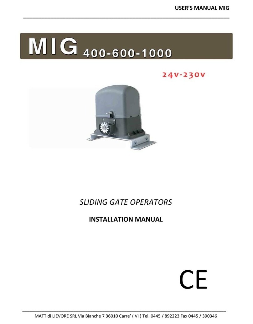
DIMOEL DIMO 700 User manual


I
AVVERTENZE IMPORTANTI PER L’INSTALLATORE.......................1
CONFORMITÁ ALLE NORMATIVE..............................................1
DATI TECNICI ...........................................................................1
LIMITI DI IMPIE O....................................................................2
VERIFICHE PRELIMINARI ...........................................................3
SCHEMA DI INSTALLAZIONE.....................................................3
MONTA IO DEL PROFILATO UIDA ......................................4
MONTA IO DEL MOTORE SUL PROFILATO ............................4
INSTALLAZIONE........................................................................4
SBLOCCO DALL'INTERNO.........................................................6
COLLE AMENTI ELETTRICI.......................................................6
IMPOSTAZIONE DEI PARAMETRI DI FUNZIONAMENTO..............7
MEMORIZZAZIONE DEI TELECOMANDI ....................................7
CANCELLAZIONE DEI TELECOMANDI .......................................7
GB
IMPORTANT REMARKS.............................................................9
DECLARATION OF CONFORMITY..............................................9
TECHNICAL SPECIFICATIONS....................................................9
USE LIMITS...............................................................................10
PRELIMINARY CHECKIN S .......................................................11
INSTALLATION LAYOUT ............................................................11
INSTALLATION OF UIDE SECTION BAR ...................................12
INSTALLATION OF MOTOR ON SECTION BAR ...........................12
INSTALLATION ..........................................................................12
INTERNAL RELEASE ..................................................................14
ELECTRICAL CONNECTIONS.....................................................14
SET-UP OF OPERATIONAL PARAMETERS ...................................15
MEMORIZATION OF REMOTE CONTROLS.................................15
DELETIN REMOTE CONTROLS ................................................15
F
CONSEILS IMPORTANTS ..........................................................17
DECLARATION DE CONFORMITÉ..............................................17
DONNEE TECHNIQUES ............................................................17
LIMITE D'EMPLOI......................................................................18
OPERATIONS PREALABLES........................................................19
SCHÉMA D’INSTALLATION ......................................................19
MONTA E DU PROFILÉ DE UIDA E ......................................20
MONTA E DU MOTEUR SUR LE PROFILÉ ................................20
INSTALLATION ..........................................................................20
DÉBLOCA E DE L'INTÉRIEUR ..................................................22
RACCORDEMENTS ÉLECTRIQUES ............................................22
PRO RAMMATION DES PARAMÈTRES DE FONCTIONNEMENT 23
MÉMORISATION DES TÉLÉCOMMANDES ................................23
EFFACEMENT DES TÉLÉCOMMANDES......................................23
P
AVISOS IMPORTANTES ............................................................33
CONFORMIDADE COM AS NORMAS ......................................33
DADOS TÉCNICOS ..................................................................33
LIMITES DE EMPRE O..............................................................34
VERIFICAÇÕES PRELIMINARES..................................................35
ESQUEMA DE INSTALAÇÃO ....................................................35
MONTA EM DO PERFILADO UIA ..........................................36
MONTA EM DO MOTOR NO PERFILADO ................................36
INSTALAÇÃO............................................................................36
DESBLOQUEIO A PARTIR DO INTERIOR ....................................38
LI AÇÕES ELÉCTRICAS ..........................................................38
PRO RAMAÇÃO DOS PARÂMETROS DE FUNCIONAMENTO....39
MEMORIZAÇÃO DOS TELECOMANDOS ..................................39
CANCELAMENTO DOS TELECOMANDOS ................................39
E
ADVERTENCIAS IMPORTANTES ................................................25
DECLARACIONES DE CONFORMIDAD......................................25
DATOS TECNICOS ....................................................................25
LIMITACIONES DE USO ............................................................26
VERIFICACIONES PRELIMINARES ..............................................27
ESQUEMA DE INSTALACIÓN ....................................................27
MONTAJE DEL PERFIL UÍA......................................................28
MONTAJE DEL MOTOR SOBRE EL PERFIL..................................28
INSTALACIÓN ..........................................................................28
DESBLOQUEO DEL INTERIOR ....................................................30
CONEXIONES ELÉCTRICAS ......................................................30
PRO RAMACIÓN DE LOS PARÁMETROS
DE FUNCIONAMIENTO ............................................................31
MEMORIZACIÓN DE LOS TELECOMANDOS..............................31
CANCELACIÓN DE LOS TELECOMANDOS................................31


ITALIANO
1
AVVERTE ZE IMPORTA TI PER
L’I STALLATORE
Per chiarimenti tecnici o problemi di installazione la V2 dispone di
un servizio di assistenza clienti attivo durante le ore di ufficio TEL.
(+39) 01 72 81 24 11
V2 S.p.A. si riserva il diritto di apportare eventuali
modifiche al prodotto senza preavviso; inoltre declina ogni
responsabilità per danni a persone o cose dovuti ad un uso
improprio o ad un’errata installazione.
LEGGERE ATTE TAME TE IL SEGUE TE MA UALE DI
ISTRUZIO I PRIMA DI PROCEDERE CO L'I STALLAZIO E.
• Il presente manuale di istruzioni è destinato solamente a
personale tecnico qualificato nel campo delle installazioni di
automazioni.
• Nessuna delle informazioni contenute all'interno del manuale
può essere interessante o utile per l'utilizzatore finale.
• Qualsiasi operazione di manutenzione o di programmazione
deve essere eseguita esclusivamente da personale
qualificato.
L’AUTOMAZIO E DEVE ESSERE REALIZZATA I CO FORMITÀ
ALLE VIGE TI ORMATIVE EUROPEE:
E 60204–1 (Sicurezza del macchinario, equipaggiamento
elettrico delle macchine, parte 1: regole generali).
E 12445 (Sicurezza nell'uso di chiusure automatizzate,
metodi di prova).
E 12453 (Sicurezza nell'uso di chiusure automatizzate,
requisiti).
• L'installatore deve provvedere all'installazione di un
dispositivo (es. interruttore magnetotermico omologato) che
assicuri il sezionamento onnipolare del sistema dalla rete di
alimentazione. La normativa richiede una separazione dei
contatti di almeno 3 mm in ciascun polo (EN 60335-1).
• Per la connessione di tubi rigidi e flessibili o passacavi
utilizzare raccordi conformi al grado di protezione IP55 o
superiore.
• L’installazione richiede competenze in campo elettrico e
meccanico; deve essere eseguita solamente da personale
qualificato in grado di rilasciare la dichiarazione di conformità
di tipo A sull’installazione completa (Direttiva macchine
98/37/EEC, allegato IIA).
• E’ obbligo attenersi alle seguenti norme per chiusure
veicolari automatizzate: EN 12453, EN 12445, EN 12978 ed
alle eventuali prescrizioni nazionali.
• Anche l’impianto elettrico a monte dell’automazione deve
rispondere alle vigenti normative ed essere eseguito a regola
d’arte. V2 S.p.A. non si assume nessuna
responsabilità nel caso in cui l’impianto a monte non
risponda alle vigenti normative e sia eseguito a regola d’arte.
• La regolazione della forza di spinta dell’anta deve essere
misurata con apposito strumento e regolata in accordo ai
valori massimi ammessi dalla normativa EN 12453.
• Consigliamo di utilizzare un pulsante di emergenza da
installare nei pressi dell’automazione (collegato all’ingresso
STOP della scheda di comando) in modo che sia possibile
l’arresto immediato del cancello in caso di pericolo.
• È vietato l’utilizzo di MOOV-SEZ50 in ambienti polverosi e
atmosfere saline o esplosive.
• È vietato l’utilizzo di MOOV-SEZ50 in ambienti esterni.
CONFORMITÁ ALLE NORMATI E
V2 SPA dichiara che gli attuatori della serie MOOV-SEZ50 sono
conformi ai requisiti essenziali fissati dalle seguenti Direttive:
2006/95/CEE bassa tensione
93/68/CEE compatibilità elettromagnetica
98/37/CEE direttiva macchine
99/05/CEE direttiva radio
Nota: Dichiara che non è consentito mettere in servizio i
dispositivi sopra elencati fino a che la macchina (cancello
automatizzato) sia stata identificata, marchiata CE e ne sia stata
emessa la conformità alle condizioni della Direttiva 89/392/EEC e
successive modifiche.
Il responsabile della messa in servizio deve fornire copia dei
seguenti documenti all’utilizzatore:
• Fascicolo tecnico
•Dichiarazione di conformità
• Marcatura CE
• Verbale di collaudo
• Registro della manutenzione
• Manuale di istruzioni ed avvertenze
Racconigi il 18 / 05 / 2007
Rappresentante legale V2 SPA
A. Livio Costamagna
V2 S.p.A.
Corso Principi di Piemonte, 65/67
12035 RACCONI I (CN) ITALY
tel. +39 01 72 81 24 11
fax +39 01 72 84 050
www.v2home.com
DATI TECNICI
MOOV-SEZ50
Alimentazione 230V - 50Hz
Potenza assorbita 100 W
Superfice porta < 8 m2
Forza di spunto 500 N
Forza nominale 350 N
Velocità media 11 cm/s
Lampada 230V - 50 Hz - 25W
Temperatura di lavoro -20 ÷ +40 °C
Ciclo di lavoro 30%
rado di protezione IP20
Peso 10 Kg
Fusibili di protezione SOURCE= 2,5 A
LI HT = 2,5 A

ITALIANO
2
LIMITI DI IMPIEGO
MOOV-SEZ50 è in grado di automatizzare porte sezionali con altezza max. fino a 2,25 m, porte basculanti a molle fino a 2,25 m e porte
basculanti a contrappesi fino a 2,45 m. Rispettare le seguenti misure per un buon esito dell’installazione.
ATTE ZIO E: Se la misura Ariportata nella figura sopra supera i 350 mm è necessario installare il kit accessorio cod. 163203. Rispettare i
limiti di impiego riportati nella figura seguente.

ITALIANO
3
ERIFICHE PRELIMINARI
Prima di procedere con l’installazione di MOOV-SEZ50 è
fondamentale verificare i seguenti punti:
• Verificare che la porta possa essere automatizzabile
(verificare la documentazione della porta). Inoltre verificare
che la struttura della stessa sia solida e adatta ad essere
automatizzata.
• Eseguire il fissaggio del motore in modo stabile utilizzando
materiali adeguati.
• Effettuare se necessario, il calcolo strutturale e allegarlo al
fascicolo tecnico.
• Verificare che la porta sia dotata di sistemi anticaduta
(indipendenti dal sistema di sospensione).
• Verificare che la porta sia funzionale e sicura.
• La porta si deve aprire e chiudere liberamente senza nessun
punto di attrito.
• La porta deve essere adeguatamente bilanciata sia prima
che dopo l'automatizzazione: fermando la porta in
qualsiaisi posizione non deve muoversi; eventualmente
provvedere ad una regolazione delle molle o dei contrappesi.
•È consigliabile installare il motoriduttore in corrispondenza
del centro della porta, al massimo è consentito lo
scostamento laterale di 100 mm necessario per installare
l’archetto accessorio J4 (vedi paragrafo 2.6 pag.6) .
• Nel caso in cui la porta sia basculante verificare che la
distanza minima tra il binario e la porta non sia inferiore
a 20 mm.
SCHEMA DI INSTALLAZIONE
Attuatore MOOV-SEZ50 cavo con spina 2 x 0.75 mm2
Fotocellule cavo 4 x 1 mm2(RX)
cavo 2 x 1 mm2(TX)
Presa Schuco -

ITALIANO
4
MONTAGGIO DEL PROFILATO GUIDA
1. Estrarre il profilato dall’imballo di cartone e verificarne
l’integrità.
2. Aprire il profilato come indicato nella figura che segue.
3. Una volta disteso il profilato far scorrere il profilato di
giunzione fino alla posizione limite evidenziata dai due fori
sagomati a C sul profilato guidacatena.
4. Regolare la tensione della catena agendo sulla vite a testa
esagonale con una chiave da 10 mm: avvitare il dado fino a
quando la catena rimane sufficientemente tesa
ATTE ZIO E: assicurarsi che il carrello di traino scorra
liberamente in tutta la lunghezza della guida. Eliminare
eventuali attriti prima di procedere con le seguenti fasi di
montaggio.
MONTAGGIO DEL MOTORE SUL PROFILATO
1. Inserire l’adattatore albero/pignone sull’albero del motore.
2. Posizionare il profilato sul motore: l’adattatore
albero/pignone deve innestarsi nell’apposita sede sul
profilato. Verificare che il profilato vada in battuta sul motore.
3. Posizionare le due staffe omega sul profilato in
corrispondenza dei fori sulla base del motore.
4. Fissare le due staffe omega con le viti autofilettanti 6 x 15
in dotazione.
INSTALLAZIONE
2.1 Smontare il sistema di chiusura della porta.
2.2 Misurare l'esatta metà della porta e tracciare dei punti di
riferimento sulla traversa superiore e sul soffitto per
facilitare il posizionamento del profilato guida.
Profilato
Vite 6x15
Staffa omega
Micro switch
Profilato di giunzione
Foro sagomato a C
Foro sagomato a C
Adattatore
albero/pignone

2.3 Ancorare la staffa alla traversa superiore della porta con
dei tasselli adatti al tipo di parete (ø minimo 8 mm).
2.4 Agganciare il profilato alla staffa utilizzando la vite a testa
sferica 6 x 80 in dotazione con il realivo dado
autobloccante.
Nel caso in cui sia necessario utilizzare le prolunghe
(kit cod. 163203) assemblarle secondo figura utilizzando viti, dadi
e rondelle contenuti nel kit.
2.5 Seguendo i riferimenti precedentemente tracciati sul
soffitto individuare i punti di fissaggio per le staffe
plastiche e per la staffa omega; forare e utilizzando dei
tasselli adatti al tipo di soffitto (ø minimo 8 mm) ancorare
l'automazione.
ATTE ZIO E: Rispettare le misure riportate nel
paragrafo LIMITI DI IMPIEGO a pag. 2.
È VIETATO appendere oggetti o pesi al profilato e al motore.
Profilato
Tassello
Vite 6x80 Staffa
Staffa plastica
Staffa omega
Vite tassello
Vite tassello
5

ITALIANO
6
2.6 Solo per porte sezionali e basculanti a molle
Fissare la piastra di traino Isulla parte superiore
della porta rispettando i riferimenti precedentemente
tracciati. Unire la barra forata Le il braccio curvo M
utilizzando 2 bulloni 6x15. Unire il braccio curvo Me la
piastra di traino Iutilizzando il perno con testa cilindrica
con l’apposita coppiglia.
2.7 Solo per porte basculanti a contrappesi
Fissare il braccio ad archetto J4 sulla parte superiore
della porta seguendo i riferimenti precedentemente
tracciati.
Le due piastre di ancoraggio (inferiore e superiore)
dell’archetto J4 devono essere sullo stesso piano, in caso
contrario aggiungere degli spessori.
Collegare la barra forata Lalla barra forata del braccio
ad archetto utilizzando 2 bulloni 6x15.
SBLOCCO DALL'INTERNO
Per sbloccare l'automazione è sufficiente tirare il pomello verso il
basso.
ATTE ZIO E: non usare il pomello per aprire la porta.
È vietato appendere oggetti al cordino di sblocco.
COLLEGAMENTI ELETTRICI
La centrale di comando all’interno di MOOV-SEZ50 è già cablata.
E’ sufficiente inserire la spina nella presa di corrente per procedere
con la programmazione dei parametri di funzionamento.
Se si utilizzano delle fotocellule è necessario collegarle come
segue:

ITALIANO
7
IMPOSTAZIO E DEI PARAMETRI DI
FU ZIO AME TO
MOOV-SEZ50 è equipaggiato
con una pratica interfaccia
che consente una rapida e
semplice programmazione
tramite il display e i quattro
tasti P,S,+,-.
Seguire attentamente le seguenti istruzioni al fine di configurare i
vari parametri in modo corretto.
1. Impostazione del finecorsa di apertura
Premere il tasto Pper 5
secondi. Il dispositivo emette
un beep e il display visualizza
1.
Tramite i stasti +e-portare la
porta nella posizione di
massima apertura.
Premere il tasto Pper memorizzare questo parametro e procedere
con quello successivo. Il display visualizza 2.
2. Impostazione del finecorsa di chiusura
Tramite i stasti +e-portare la
porta nella posizione di
massima chiusura.
Premere il tasto Pper
memorizzare questo
parametro e procedere con
quello successivo.
Il display visualizza 3.
3. Apprendimento delle forze
Premere il tasto +:
la porta apre.
Quando arriva a finecorsa
premere il tasto -:
la porta chiude.
Durante questa fase il dispositivo apprende i livelli di forza
necessari per aprire e chiudere la porta.
Premere il tasto Pper memorizzare questo parametro e procedere
con quello successivo. Il display visualizza 4.
4. Regolazione della sensibilità
Questo menù permette di
aumentare o diminuire la
sensibilità del dispositivo
quando la porta incontra un
ostacolo.
Questo parametro è già impostato su un valore medio (4) che
dovrebbe essere ottimale per la maggior parte delle installazioni.
I vari livelli sono visualizzati come segue:
5. Selezione del pulsante del telecomando
Questo menù permette di
selezionare il pulsante che si
intende utilizzare per pilotare
l’automazione. Questa
funzione può essere utile nel
caso in cui si vogliano pilotare
2 automazioni differenti con
lo stesso telecomando ma con
pulsanti diversi.
Premere il tasto -per selezionare il pulsante 1, il
display visualizza:
Premere il tasto +per selezionare il pulsante 2, il
display visualizza:
In seguito per uscire dalla programmazione tenere premuto per 5
secondi il tasto P: il display visualizza 0ed entra in stand by.
L’automazione è pronta per l’utilizzo.
MEMORIZZAZIONE DEI TELECOMANDI
1. Premere il tasto Sfino a quando si accende il pallino sul display.
2. Rilasciare il tasto Se
premere per 2 volte il
tasto del telecomado:
il dispositivo emette un
BEEP ed il pallino si
spegne per confermare
l’avvenuta memorizzazione
3. Ripetere la procedura per gli altri trasmettitori da memorizzare.
CANCELLAZIONE DEI TELECOMANDI
1. Premere e mantenere premuto il tasto S: dopo circa 1
secondo si accende il pallino sul display.
2. Mantenere il tasto premuto fino a quando il pallino sul
display si spegne: i telecomandi sono stati cancellati.
0
0 0 0 0 0 0
i
5
8
2
3
4
1
+-
23456
8
0

ITALIANO
8

ENGLISH
9
IMPORTANT REMARKS
For any installation problems please contact V2 S.p.A.
TEL. (+39) 01 72 81 24 11
V2 S.p.A. has the right to modify the product without
previous notice; it also declines any responsibility to
damage or injury to people or things caused by improper
use or wrong installation.
PLEASE READ THIS I STRUCTIO MA UAL VERY
CAREFULLY BEFORE I STALLI G A D PROGRAMMI G YOUR
CO TROL U IT.
•This instruction manual is only for qualified technicians, who
specialize in installations and automations.
• The contents of this instruction manual do not concern the
end user.
•Every programming and/or every maintenance service should
be done only by qualified technicians.
AUTOMATIO MUST BE IMPLEME TED I COMPLIA CE
WITH THE EUROPEA REGULATIO S I FORCE:
E 60204-1 (Machinery safety. electrical equipment of
machines, part 1: general rules)
E 12445 (Safe use of automated locking devices, test
methods)
E 12453 (Safe use of automated locking devices,
requirements)
• The installer must provide for a device (es. magnetotermical
switch) ensuring the omnipolar sectioning of the equipment
from the power supply. The standards require a separation of
the contacts of at least 3 mm in each pole (EN 60335-1).
• To connect flexible or rigid pipes, use pipefittings having the
IP55 insulation level.
• Installation requires mechanical and electrical skills,
therefore it shall be carried out by qualified personnel only,
who can issue the Compliance Certificate concerning the
whole installation (Machine Directive 98/37/EEC, Annex IIA).
• The automated vehicular gates shall comply with the
following rules: EN 12453, EN 12445, EN 12978 as well as
any local rule in force.
• Also the automation upstream electric system shall comply
with the laws and rules in force and be carried out
workmanlike. V2 S.p.A. declines any responsibility in
case of automation upstream electric system not complying
with the laws and rules in force and not carried out
workmanlike.
• The door thrust force adjustment shall be measured by
means of a proper tool and adjusted according to the max.
limits, which EN 12453 allows.
• We recommend to make use of an emergency button, to be
installed by the automation (connected to the control unit
STOP input) so that the gate may be immediately stopped in
case of danger.
• The use of MOOV-SEZ50 in dusty, saline or explosive
environment is forbidden.
DECLARATION OF CONFORMITY
V2 S.p.A. declares that the series of MOOV-SEZ50 actuators are in
conformity with the provisions of the following EC directives:
73/23/EEC electrical safety
93/68/EEC electromagnetic compatibility
99/05/EEC radio directive
98/37/EEC machine directive
Note: Declares that the above mentioned devices may not be ope-
rated until the machine (automated gate) is identified, CE-labeled,
and declared to be compliant to the specifications of Directive
89/392/EEC and following modifications.
The person in charge for the machine start-up must provide the
following records:
• Technical specification paper
• Declaration of conformity
•CE-labeling
• Testing record
• Maintenance record
• Operation manual and directions
Racconigi 18 / 05 / 2007
V2 S.p.A. legal representative
A. Livio Costamagna
V2 S.p.A.
Corso Principi di Piemonte, 65/67
12035 RACCONI I (CN) ITALY
tel. +39 01 72 81 24 11
fax +39 01 72 84 050
www.v2home.com
TECHNICAL SPECIFICATIONS
MOOV-SEZ50
Power supply 230V - 50Hz
Absorbed power 100 W
Door Area < 8 m2
Peak Force 500 N
Nominal Force 350 N
Average speed 11 cm/s
Lamp 230V - 50 Hz - 25W
Working temperature -20 ÷ +40 °C
Working cycle 30%
Protection IP20
Weight 10 Kg
Protection fuses SOURCE= 2,5 A
LI HT = 2,5 A

ENGLISH
10
USE LIMITS
MOOV-SEZ50 can automate sectional doors max 2,25 m high, balanced doors max 2,25 m and counterweight balanced door max 2,45
m. Take into consideration in order to install properly.
CAUTIO : It measurement Ashown in the figure above is greater than 350 mm accessory kit p/n 163203 must be installed. Respect the
limits of use called for in the figure below.

ENGLISH
11
PRELIMINARY CHECKINGS
Before installing MOOV-SEZ50, please check the following basic
points:
• The door must be suitable to be automated (check the door
operation manual and directions). The door structure itself
must be stout and appropriate to be automated.
• Fix the engine steadily and using suitable material.
• If necessary, make the structural calculation and enclose to
the technical specification paper.
• Check the door to be provided with anti-fall system
(independent of the suspension system)
•The door must be functional and safe.
• The door must open and close easily without any friction.
• The door must be properly balanced both before and after its
automation: stopping the door in any position, it must not
move (carry out a balance weight adjustment, if necessary).
• It is advisable to install the geared motor in the centre of the
door; it is permitted to move aside 100 mm to install the
sliding arm accessory J4 (see paragraph 2.7 page 14).
• In case of counterbalanced door, check that the minimum
distance between the track and the door must not be under
20 mm.
I STALLATIO LAYOUT
Actuator MOOV-SEZ50 cable con spina 2 x 0.75 mm2
Photocells cable 4 x 1 mm2(RX)
cable 2 x 1 mm2(TX)
Schuco socket -

ENGLISH
12
INSTALLATION OF GUIDE SECTION BAR
1. Remove the section bar from its cardboard packaging and
check its integrity.
2. Unfold the section bar as indicated in the figure below.
3. Once the section bar is elongated, slide the connecting
section bar to the end position indicated by the two C shaped
holes on the chain-guide section bar.
4. Adjust the tension of the chain using the Allen-head screw
with a 10 mm Allen-wrench: turn the bolt until the chain is
sufficiently tight.
CAUTIO : Make certain that the draw slide slides
freely along the entire length of the guide. Eliminate any
friction prior to proceeding with the next phases of
installation.
INSTALLATION OF MOTOR ON SECTION BAR
1. Insert the shaft/pinion adapter on the motor shaft.
2. Position the section bar on the motor: The shaft/pinion
adapter must fit into the seat on the section bar. Verify that
the section bar fits snuggly against the motor.
3. Position the two omega brackets on the section bar so that
they correspond with the holes on the base of the motor.
4. Fasten the two omega brackets using the 6 x 15 self-
threading screws provided.
INSTALLATION
2.1 Disassemble the door's locking system.
2.2 Measure the door, and at exactly half its height mark the
reference points on the upper crossbeam and on the
ceiling to facilitate positioning of the guide section bar.
Section Bar
Screws 6x15
Omega Bracket
Micro switch
Connecting Section Bar
C Shaped hole
C Shaped hole
Shaft/Pinion
Adapter

ENGLISH
2.3 Fasten the bracket to the upper crossbeam of the door
using plugs suitable for the type of wall (ø minimum 8 mm).
2.4 Hook the section bar on the bracket using the 6 x 80 ball
stud provided with its self-locking nut.
In cases requiring the use of the extensions (kit p/n 163203),
assemble the extensions according to the figure provided using
the screws, nuts and washers contained in the kit.
2.5 Using the reference markings made on the ceiling, identify
the points for fastening the plastic brackets and for the
omega bracket. Drill holes, and using plugs suitable for the
type of ceiling (ø minimum 8 mm) fasten the actuator.
CAUTIO : Respect the dimensions indicated in the
paragraph LIMITS FOR USE on page 10.
IT IS PROHIBITED to hang objects of weights on the section
bar or on the motor.
Section Bar
Plug
Screws 6x80 Bracket
Omega Bracket
Plug Screw
Plastic Bracket
Plug Screw
13

ENGLISH
14
2.6 Only for sectional and spring operated garage doors
Fasten the draw slide Ion the upper portion of the door
maintaining the previously marked reference points.
Connect the perforated bar Land the curved arm Musing
2, 6 x 15 bolts. Connect the curved arm Mand the draw
plate Iusing the cylindrical headed pivot with the provided
split pin.
2.7 Only for counter-weighted garage doors
Fasten the arch arm J4 on the upper portion of the door
maintaining the previously marked reference points.
The two anchor plates (upper and lower) of the arch J4
must be in the same plane. If not, add shims.
Connect the perforated bar Lto the perforated bar of the
arch arm using 2, 6 x 15 bolts.
INTERNAL RELEASE
To release the actuator, it is only necessary to pull the knob
downwards.
CAUTIO : Do not use the knob to open the door.
It is prohibited to hand objects off the release cord.
ELECTRICAL CONNECTIONS
The control panel inside MOOV-SEZ50 is already cabled.
You just need to plug it in the electrical outlet to proceed with
operational parameter programming.
If using photocells, they must be connected as follows:

ENGLISH
15
SET-UP OF OPERATIO AL PARAMETERS
MOOV-SEZ50 is equipped
with a practical interface that
allows rapid and simple on-
display programming using
four keys: S,P, +, and -.
Follow the instructions below carefully in order to configure the
parameters correctly.
1. Set-up of opening limit
Press the Pkey for 5 seconds.
The device will beep and the
display will show 1.
Using the + and - keys, move
the door to the maximum
open position.
Press the Pkey to memorize
this parameter and proceed to the next. The display will show 2.
2. Set-up of closing limit
Using the + and - keys, move
the door to the maximum
closed position.
Press the Pkey to memorize
this parameter and proceed
to the next.
The display will show 3.
3. Learning Forces
Press the + key:
the door opens.
When it reaches the limit,
press the - key:
the door closes.
During this phase, the device
will learn all of the force levels necessary to open and close the
door.
Press the Pkey to memorize this parameter and proceed to the
next. The display will show 4.
4. Adjust the sensitivity
This menu allows the
sensitivity of the device to be
increased or decreased when
the door meets an obstacle.
This parameter is already set
to an average value (4) which
should be optimal for most
installations.
The various levels are shown as follows:
5. Select the remote control buttons
This menu allows the
selection of the buttons to
control the actuator. This
function can be useful should
it be desirable to control 2
actuators using the same
remote control, but with
different buttons.
Press the - key to select button 1, the display will
show:
Press the - key to select button 2, the display will
show:
Thereafter, to exit the programming, hold the Pkey pressed for 5
seconds: the display will show 0and will go into standby. The
actuator is ready for use.
MEMORIZATION OF REMOTE CONTROLS
1. Press key Suntil the dot
appears on the display.
2. Release key Sand press
the remote control button
twice: the device emits a
BEEP and the dot is
turned off to confirm
storage in the memory has
occurred
3. Repeat the procedure for the other remote controls to be
memorized.
DELETING REMOTE CONTROLS
1. Press and hold key S: after approx. 1 second the dot appears
on the display.
2. Hold the key until the dot on the display is turned off: the
remote controls have been deleted.
0
0 0 0 0 0 0
i
5
8
2
3
4
1
+-
23456
8
0

ENGLISH
16
This manual suits for next models
1
Table of contents
Languages:
Other DIMOEL Gate Opener manuals

