B&G Hydra 2000 User manual

Hydra 2000 User Manual
HB-0844-02
PRODUCT LIABILITY AND SAFETY WARNINGS
PRODUCT LIABILITY
Brookes and Gatehouse Limited accept no responsibility
for the use and/or operation of this equipment. It is the
user’s responsibility to ensure that under all circumstances
the equipment is used for the purposes for which it has
been designed.
WARNING - ELECTRICAL HAZARD
This equipment uses high voltage electrical power. Contact
with high voltages may result in injury and/or loss of life.
WARNING - CALIBRATION
The safe operation of this equipment is dependent on
accurate and correct calibration. Incorrect calibration of
this equipment may lead to false and inaccurate
navigational readings placing the yacht into danger.
WARNING - NAVIGATION HAZARD
The Hydra 2000 is an Electronic Navigation System and is
designed to assist in the navigation of your yacht. It is not
designed to totally replace conventional navigation
procedures and precautions and all necessary precautions
should be taken to ensure that the yacht is not placed into
danger.
CAUTION
This equipment is designed for use with a power supply
source of 12v dc. The application of any other power supply
may result in permanent damage to the equipment.

Hydra 2000 User Manual
HB-0844-02
RECORD OF AMENDMENTS
Date Amendment
Number Description Signature

Hydra 2000 User Manual
HB-0844-02
PART 1 - INTRODUCTION
CONTENTS
Para Page
1.1 SYSTEM DESCRIPTION 1-3
1.2 PROCESSORS 1-3
1.2.1 Main Processor Unit 1-3
1.2.2 Expansion Unit 1-4
1.3 SENSORS 1-4
1.3.1 Masthead Unit 1-4
1.3.2 Paddle Wheel 1-4
1.3.3 Sonic Speed Unit 1-4
1.3.4 Depth Sensor 1-5
1.3.5 Super Halcyon 3 Fluxgate Compass 1-5
1.3.6 Halcyon 2000 Compass 1-5
1.3.7 Additional Sensors 1-5
1.4 DISPLAYS 1-5
1.4.1 NMEA Full Function Display (FFD) 1-5
1.4.2 Standard FFD 1-6
1.4.3 20/20 Display 1-6
1.4.4 Analogue Indicators 1-6
1.4.5 Halcyon Display 1-7
1.5 CALIBRATION 1-7
1.6 DAMPING 1-7
1.7 MENU STRUCTURE 1-8
ILLUSTRATIONS
Fig No Page
1.1 Typical Hydra 2000 System Block Diagram 1-2
TABLES
Table No Page
1.1 Function Menu Choices 1-9
1.2 Operational Menu Choices 1-11

Hydra 2000 User Manual
HB-0844-02
MastHead
Unit
20/20
20/20
Halcyon Compass
DisplayFFD
FFD
Hydra 2000
MainProcessor
SonicSpeed Unit
Network
Boat
Speed
NMEA FFD
ChartTable
Deck
Mast
Hull
Halcyon
GPS Antenna
Unit
GPS Plus
Depth
000
EP
000
000
Halcyon 2000
Compass
AdditionalSensors
Sea and AirTemperature,Heel,
Trim,BarometricPressure and Strain
Fig 1.1 - Typical Hydra 2000 System Block Diagram

Hydra 2000 User Manual
HB-0844-02
PART 1 - INTRODUCTION
1.1 SYSTEM DESCRIPTION
The Hydra 2000 is a fully integrated instrumentation system that
displays information obtained from various sensors on a choice of
displays positioned throughout the yacht. Information is fed from
the sensors to a Main Processor. From the information gathered
by the sensors the Main Processor distributes information to the
various displays via the Fastnet cable. This allows it to carry out a
wide range of functions including dead reckoning, true wind speed
and true wind direction, etc. These functions are controlled from a
Full Function Display (FFD).
A typical system is shown in Figure 1.1 - Typical Hydra 2000
System Block Diagram.
1.2 PROCESSORS
1.2.1 Main Processor Unit
The Main Processor is the heart of the system and can be
connected to sensors that measure the following:
Boat Speed/Log
Depth
Sea Temperature
Air Temperature
Compass Heading
Apparent Wind Speed
Apparent Wind Angle
Ship's Supply Voltage
Heel Angle
Trim Angle
Mast Rotation
Barometric Pressure
Forestay Load
From this information the Main Processor Unit is then able to
calculate the following additional functions:
Average Boat Speed
Velocity Made Good (VMG) upwind/downwind
Resettable Log
Dead Reckoned Course and Distance

Hydra 2000 User Manual
HB-0844-02
Leeway
Heading Corrected for Leeway (Course)
True Wind Speed
True Wind Angle
True Wind Direction
Heading on Next Tack or Gybe
Pressure Trend
In addition, the processor provides four outputs for analogue
indicators. Any one of eight different types of analogue indicator
can be used on any one of these outputs.
It also contains the battery backed memory that stores all the
calibration, damping and alarm settings whilst the power is OFF.
These are adjustable from any FFD.
1.2.2 Expansion Unit
The Expansion Unit allows a further four analogue indicators and a
number of additional sensors to be added to the system. Further
details are given in Part 5 - Options.
1.3 SENSORS
1.3.1 Masthead Unit
The Masthead Unit senses apparent wind speed and wind angle.
The unit is light weight and sealed.
1.3.2 Paddle Wheel
The Paddle Wheel Speed Sensor is designed primarily for
cruising yachts and consists of a paddle wheel that protrudes
through the hull via a housing. So that the paddle wheel may be
cleaned at regular intervals the housing is provided with a flap
valve that closes automatically when the unit is pulled back into the
yacht.
1.3.3 Sonic Speed Unit
The Sonic Speed Unit provides highly accurate and stable boat
speed measurement. It does not rely on mechanical moving parts
that require constant attention to protect them from weed, etc. The
transducers are fitted virtually flush with the hull, creating almost
zero drag, and can be painted, faired or anti-fouled.

Hydra 2000 User Manual
HB-0844-02
1.3.4 Depth Sensor
This can either be a removable through-hull unit, or moulded in-hull
for reduced drag. The depth datum can be set to the waterline, the
bottom of the keel or from the transducer.
1.3.5 Super Halcyon 3 Fluxgate Compass
This fluxgate compass sensor is fully gimballed in a bath of oil,
ensuring accurate readings at all normal angles of heel and pitch.
The unit features automatic deviation correction, thus eliminating
the need for expert compass adjustment.
1.3.6 Halcyon 2000 Compass
The Halcyon 2000 Compass is a high performance electronic
fluxgate compass for use on both sailing and power craft. It is
intended to be connected to Hercules 2000, Hydra 2000 or HS
2000 instrument systems through the B&G Fastnet Network.
The Halcyon 2000 Compass has the ability to ‘learn’ the magnetic
effect of the vessel on the compass and automatically apply
deviation correction.
1.3.7 Additional Sensors
Additional sensors provide either single inputs, or improve the
accuracy of other functions on the system and they are discussed
in Part 5 - Options.
1.4 DISPLAYS
1.4.1 NMEA Full Function Display (FFD)
This is the standard system display and every Hydra 2000 must
contain one NMEA FFD. The Standard FFDs and the other
display types, described in this Section, are options with which the
system can be expanded and made even more powerful.
The FFD's name gives an indication to the fact that they are really
much more than just a display. It is a terminal for the whole
system, allowing you to control everything from the functions
displayed on them (and at the 20/20’s) to the calibration of the
system.

Hydra 2000 User Manual
HB-0844-02
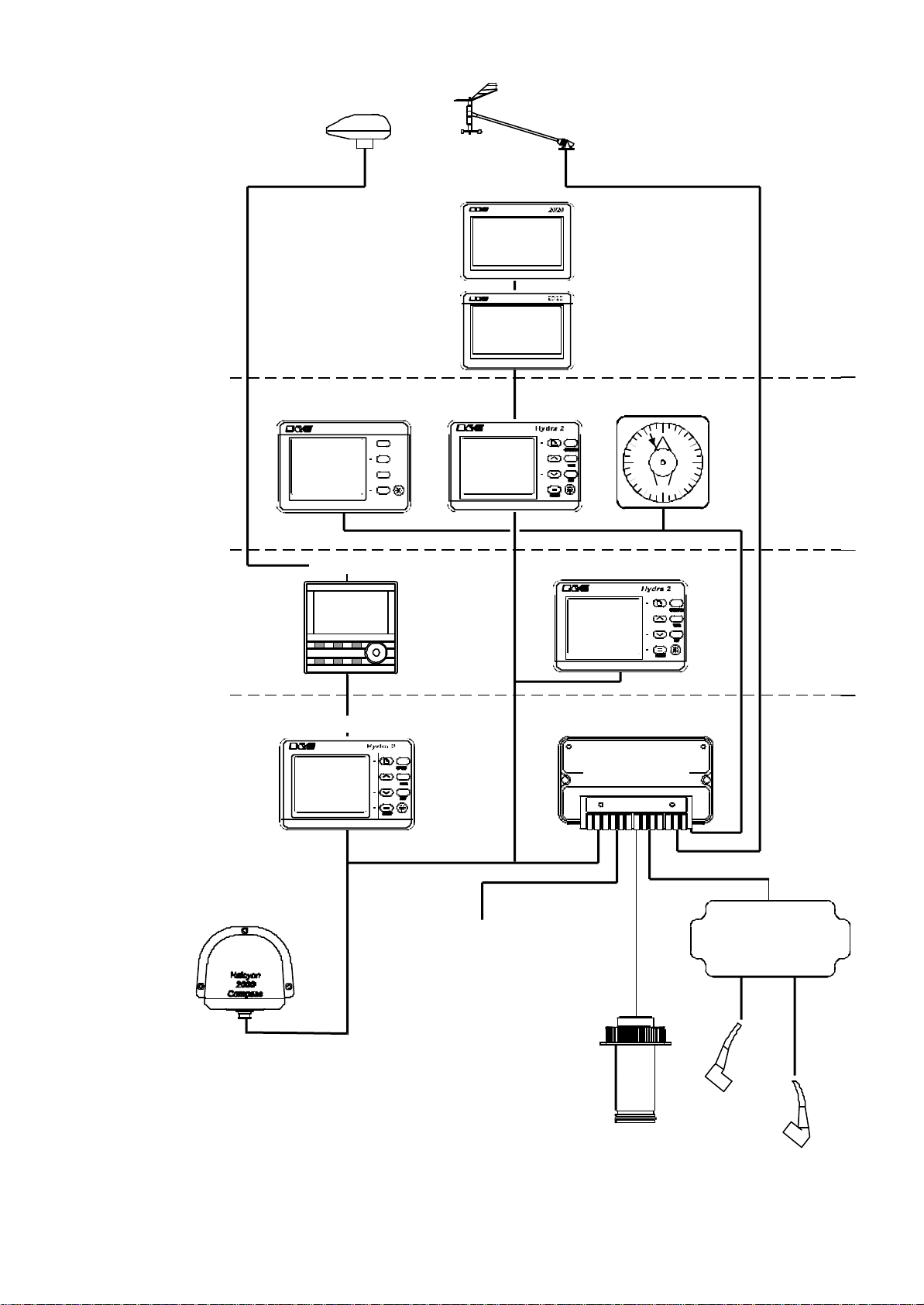
The FFD simultaneously displays two functions. Any system
function can be called up on any FFD and can be placed on the
system, all with full control of the Hydra 2000.
The NMEA FFD contains a NMEA interface which allows your
Hydra 2000 System to be connected to devices such as position
fixers, autopilots, chart plotters and radars, etc. from different
manufacturers. For example your GPS Plus may be at the chart
table, but you require its information to steer by on deck. Your
Hydra displays can show that information if interfaced to your GPS
Plus. The Hydra System can also provide information to your
autopilot.
NMEA is the National Marine Electronics Association, who have
produced a number of standard specifications for the
interconnection of marine electronic instruments. These standards
specify the electrical signals and the format of the data to be
transferred.
Part 2 - Operating Information describes in detail the use of the
FFD keyboard to control the Hydra 2000.
Part 4 - Installation Information shows NMEA in/out specifications.
1.4.2 Standard FFD
The Standard FFD is functionally identical and similar in
appearance to the NMEA FFD. The only difference is that the
Standard FFD is not fitted with a NMEA interface.
1.4.3 20/20 Display
The Hydra 2000 20/20 is a lightweight, large digit, liquid crystal
display - it can be configured from any FFD or a remote button to
display any system function.
The 20/20's operation is fully explained in Part 5 - Options.
1.4.4 Analogue Indicators
There is a wide range of analogue indicators available. Refer to
Part 5 - Options for full details.

Hydra 2000 User Manual
HB-0844-02
1.4.5 Halcyon Display
This is a dedicated compass display that shows heading in digital
form and has a bar graph display that can be used as a steering
indicator.
Refer to Part 5 - Options for further details.
1.5 CALIBRATION
Before using the Hydra 2000 for navigational purposes it is
important that the system is correctly calibrated for your
installation. The calibration process has been simplified as much
as possible, so that all you need is accurate information. This is
fully explained in Part 3 - Calibration.
1.6 DAMPING
A useful feature is that the damping on most functions is
adjustable. This allows you to slow down the response of the
function if it is too jumpy in rough weather, and similarly to speed it
up if it is too slow in flat water.
The damping works by averaging the numbers over a user
adjustable time period. The more you increase this time period
the smoother the data readings will get, but the longer it will take to
see the effect of any change.
Similarly the lower it is the bigger the jumps you will get in the
numbers but the response to any change will be quicker -
remember, high damping for rough weather, low damping for calm
weather.
Damping should not be confused with the update rate which is the
number of times each second that the function value is sent to the
display. It is fixed for all the functions.

Hydra 2000 User Manual
HB-0844-02
1.7 MENU STRUCTURE
The central concept to the operation of the system is the structure
of the Function Menus accessed through the FFD, and once this
is grasped, operation very quickly becomes familiar.
The idea of structured layers of menus is one seen everywhere in
modern software, and regular computer users will be familiar with
this concept.
The principle is that at any one level there is a set of choices
which you can scroll through (select) until you find the one you
want. Having found the correct menu entry, it is then selected - the
FFD then displays the first choice in the next level of menu down.
Here you once again scroll through the available options until you
find and select your choice.
The function options available through each Menu Choice are
listed in Table 1.1 - Function Menus. Operational Menu choices
together with the Function Menu applicable are listed in Table 1.2 -
Operational Menu Choices.
Note
The Functions available to the user are dependent on the range of
sensors fitted to the system.
Details of the sensors required for each function are fully
explained in Part 3 - Operating Information.

Hydra 2000 User Manual
HB-0844-02
Table 1.1 - Function Menu Choices
FUNCTION MENU CHOICE FUNCTION
TEXT
Speed Boat Speed
Average Speed
Velocity Made Good
BOAT SPD
AVG SPD
VMG
Log Stored Log
Trip Log STD LOG
TRIP LOG
Depth Depth - Meters
Depth - Feet
Depth - Fathoms
DEPTH M
DEPTH FT
DEPTH FM
Navigate
Heading
Off Course
Dead Reckoning Course
Dead Reckoning Distance
Course
Leeway
Tidal Set
Tidal Drift
HEADING
OFF CRSE
D/R CRSE
D/R DIST
COURSE
LEEWAY
TIDE SET
TIDE RTE
Wind
Apparent Wind Speed
True Wind Speed
Apparent Wind Angle
True Wind Angle
True Wind Direction
Head/Lift Trend
Apparent Wind Speed m/s
True Wind Speed m/s
APP W/S
TRUE W/S
APP W/A
TRUE W/A
TRUE DIR
LIFT/HDR
APP W/S MS
TRUE W/S MS
Perform
Opposite Tack
Layline
Heel Angle
Fore/Aft Trim
Mast Angle
Wind Angle to the Mast
OPP TACK
LAYLINE
HEEL
TRIM
MAST ANG
W/A MAST

Hydra 2000 User Manual
HB-0844-02
Table 1.1 - Function Menu Choices (Contd.)
FUNCTION MENU CHOICE FUNCTION
TEXT
Waypoint
Bearing W/point to W/point Mag.
Bearing W/point to W/point True
Bearing to W/point Rhumb Mag.
Bearing to W/point Rhumb True
Brg to W/point Great Circle Mag.
Brg to W/point Great Circle True
Distance to Waypoint Rhumb
Distance to Waypoint Great Circle
Course over Ground Mag.
Course over Ground True
SPD over Ground
VMG to Waypoint
Estimated Time of Arrival to WPT
Cross Track Error
BRG W-W M
BRG W-W T
BTW RMB M
BTW RMB T
BTW GC M
BTW GC T
DTW RMB
DTW GC
CRSE O/G M
CRSE O/G T
SPD O/G
VMG WPT
ETA WPT
CROSS TR
Motor Battery Voltage VOLTS
Temperature Sea Temperature °C
Sea Temperature °F
Air temperature °C
Air Temperature °F
SEA TEMP °C
SEA TEMP °F
AIR TEMP °C
AIR TEMP °F
Timer Timer TIMER
Miscellaneous
Linear 1
Linear 2
Linear 3
Linear 4
Barometric Pressure
Barometric Pressure Trend
Rudder Angle
LINEAR 1
LINEAR 2
LINEAR 3
LINEAR 4
BAROMETER
PR TREND
RUDDER
External Remote 0 to 9 REMOTE 0
TO 9

Hydra 2000 User Manual
HB-0844-02
Table 1.2 - Operational Menu Choices
OPERATION AVAILABLE
FUNCTION(S) OPERATIONAL
CHOICE
Log Control Trip Log
D/R Course
D/R Distance
RESET
RUN
FREEZE
Timer Control Timer
FREEZE
START 0
START 5
START 10
START 15
PR Trend
Control PR Trend PERIOD
RESET
Alarm Control
BOAT SPD
APP W/S
DEPTH
VOLTS
SEA TEMP
AIR TEMP
ALL OFF
HI ALARM
HI ON
HI OFF
LO ALARM
LO ON
LO OFF
Sector Alarm
Control HEADING
APP W/A
ALL OFF
SECTOR
SECT ON
SECT OFF
Damping
Control
BOAT SPD
APP W/A
APP W/S
HEADING
TRUE W/A
TRUE W/S
HEEL
TRIM
TIDE
RUDDER ANGLE
DAMPING VALUE

Hydra 2000 User Manual
HB-0844-02
Table 1.2 - Operational Menu Choice (Contd.)
OPERATION AVAILABLE
FUNCTION(S) OPERATIONAL
CHOICE
Calibrate Log
(AUTO CAL) BOAT SPD
STD LOG
SINGLE
PORT CAL
STBD CAL
CAL DIST
STRT RUN
STOP RUN
END CAL
Calibrate Log
(MANL CAL) BOAT SPD
STD LOG SINGLE
PORT CAL
STDB CAL
Calibrate Log
(Ref Cal) Boat SPD Reference CAL
Calibrate Temp Sea Temp °C
Sea Temp °F OFFSET C
Calibrate
Datum DEPTH DATUM (+/-)
Calibrate App
W/A APP W/A MHU ANGL
Calibrate App
W/S APP W/S MHU CAL
MHU OFFS
Calibrate Wind TRUE W/A
TRUE W/S CORRECTN
All Other
Calibrate
Functions Selected Function CAL VALUE 1
CAL VALUE 2
CAL VALUE 3
CAL VALUE 4

Hydra 2000 User Manual
Part 2 - Operating Information
HB-0844-02
2-1
PART 2 - OPERATING INFORMATION
CONTENTS
Para Page
2.1 FULL FUNCTION DISPLAY (FFD) 2-4
2.1.1 The Keys 2-5
2.1.2 Power/Lights Key 2-5
2.1.3 Page Key 2-5
2.1.4 Scroll Keys 2-6
2.1.5 Enter/Reset Key 2-6
2.1.6 Speed/Depth (SPD/DEP) Key 2-7
2.1.7 Wind Key (WIND) 2-7
2.1.8 Navigation (NAV) Key 2-7
2.1.9 Remote Button Operation 2-8
2.2 20/20 DISPLAY 2-8
2.3 SUPER HALCYON 3 AND HALCYON 2000
COMPASS 2-8
2.4 HALCYON DISPLAY 2-9
2.5 EXAMPLES OF OPERATION 2-9
2.5.1 Function Selection 2-9
2.5.2 Page Display Configuration 2-10
2.5.3 NAV Key Configuration 2-10
2.5.4 Damping Adjustment - Boat Speed 2-11
2.6 EXAMPLES OF CALIBRATION 2-12
2.6.1 Calibration Adjustment - Boat Speed 2-12
2.6.2 Calibration Adjustment - Depth 2-12
2.6.3 Calibration Adjustment - Wind Angle 2-13
2.7 ALARMS 2-14
2.7.1 Alarm Control 2-14
2.7.2 Alarm Types 2-14
2.7.3 Set LO Alarm - Depth 2-15
2.7.4 Switch Alarms On/Off 2-16
2.7.5 Disable Alarms 2-16

Hydra 2000 User Manual
Part 2 - Operating Information
HB-0844-02
2-2
2.8 TRIP FUNCTIONS 2-16
2.8.1 Fast Reset 2-17
2.8.2 Reset Timer 2-17
2.8.3 Reset Trip Log 2-18
2.9 LIGHTING CONTROL 2-18
2.9.1 Select Local Control 2-19
2.9.2 Select System Control 2-19
2.10 OPERATING NOTES 2-19
2.11 OPERATING FUNCTIONS 2-20
2.11.1 Air Temperature 2-20
2.11.2 Apparent Wind Angle 2-20
2.11.3 Apparent Wind Speed 2-21
2.11.4 Average Speed 2-21
2.11.5 Barometric Pressure 2-22
2.11.6 Barometric Pressure Trend 2-22
2.11.7 Battery Voltage 2-23
2.11.8 Bearing to Waypoint 2-23
2.11.9 Bearing Waypoint to Waypoint 2-23
2.11.10 Boat Speed 2-24
2.11.11 Course 2-24
2.11.12 Course Over Ground 2-25
2.11.13 Dead Reckoning 2-25
2.11.14 Depth 2-27
2.11.15 Distance to Waypoint 2-27
2.11.16 Fore/Aft Triim 2-28
2.11.17 Heading 2-28
2.11.18 Heading on Opposite Tack 2-29
2.11.19 Head Lift Trend 2-29
2.11.20 Heel Angle 2-29
2.11.21 Leeway 2-30
2.11.22 Layline Distance 2-30
2.11.23 Local Time of Day 2-31
2.11.24 Mast Angle 2-31
2.11.25 Next Waypoint Distance 2-31
2.11.26 Off Course 2-32
2.11.27 Rig Tension 2-32
2.11.28 Rudder Angle 2-33
2.11.29 Sea Temperature 2-33

Hydra 2000 User Manual
Part 2 - Operating Information
HB-0844-02
2-3
CONTENTS (Contd.)
Para Page
2.11.30 Speed Over Ground 2-33
2.11.31 Stored Log 2-34
2.11.32 Tidal Set and Drift 2-34
2.11.33 Timer 2-35
2.11.34 Time to Layline 2-36
2.11.35 Time to Waypoint 2-36
2.11.36 Trip Log 2-36
2.11.37 True Wind Angle 2-37
2.11.38 True Wind Direction 2-38
2.11.39 True Wind Speed 2-39
2.11.40 Velocity Made Good (VMG) 2-39
2.11.41 Wind Angle to the Mast 2-40
ILLUSTRATIONS
Fig No Page
2.1 Full Function Display 2-4
2.2 Sector Alarm 2-14
2.3 Dead Reckoning 2-26
2.4 Wind Angle 2-38
2.5 Calculation of VMG 2-40

Hydra 2000 User Manual
Part 2 - Operating Information
HB-0844-02
2-4
PART 2 - OPERATING INFORMATION
2.1 FULL FUNCTION DISPLAY (FFD)
The Hydra 2000 System is easily operated using the keys on any
one of the NMEA or Standard Full Function Displays (FFD).
Fig 2.1 - Full Function Display
The information displayed on each FFD consists of a page of
information comprising an upper display and a lower display. The
FFD has four pages available that may be configured to display
any function available in either the upper or lower displays. The
user may also select any function for display at any time in either
the upper or lower display.
In addition, three factory set pages relating to Wind, Speed/Depth
and Navigate functions are incorporated into each FFD. These
pages are accessed by pressing the related key on the FFD.
Table of contents
Other B&G Marine Equipment manuals

B&G
B&G RAM T2 User manual

B&G
B&G H5000 Pilot Use and care manual

B&G
B&G Zeus2 series User manual

B&G
B&G Zeus3 Glass Helm User manual

B&G
B&G Hydra Pilot Instruction Manual

B&G
B&G H1000-WDI User manual

B&G
B&G h1000 pilot User manual

B&G
B&G RAM T0 User manual

B&G
B&G h3000 User manual

B&G
B&G Zeus3 Glass Helm User manual
Popular Marine Equipment manuals by other brands

Skipper
Skipper ED 161 Operator's manual

Eaton
Eaton MEDC EV21 Technical manual

Lecomble & Schmitt
Lecomble & Schmitt VHM 26 DTP Mounting instructions

MEDC
MEDC DB5FM Technical manual

Orisec
Orisec INT-CS installation instructions

JRC
JRC Alphatron Marine Rudder Feedback Unit HD Installation and operation manual