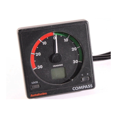
AUTOHELM Masterview ST80 User manual

Z211 ST80 Masterview Service Procedures
D2601-1
masterview
Z211Z211
Z211Z211
Z211
ST80 Masterview
ST80MasterviewServiceManual83028-1 1

CE MARKING OF EQUIPMENT/REPLACEMENT PARTS
WARNING
IftheAutohelmequipmentunderrepair,test,calibration,installationor
settingtoworkcarriestheEuropeanCEmark,only partsand components
suppliedorapprovedforsuchusebyAutohelm should beusedinorderto
maintaincompliancewiththerelevantCErequirements.
Incorporation,useorattachment,by any means,ofpartsorcomponents
notsuppliedforornot approvedforsuch use byAutohelmor,ifsuppliedor
approved forusebyAutohelm, not properlyfittedinaccordancewith
instructionspublished,providedorrecommendedbyAutohelm,maycause
theequipmenttomalfunctionand,inparticular,tobecomeunsafeortono
longermeettherelevantCErequirements.Inthesecircumstances,
RaytheonMarineEuropeLtdexcludesliabilitytothefullestextentpermissi-
bleinlawforany loss ordamageincludingany liability foritscontributionto
suchlossordamagebyits negligent actsoromissions.
Z211Z211
Z211Z211
Z211
ST80 Masterview
2 MasterviewServiceManual83028_1

Contents
1. Description ....................................................................5
2. Operation ......................................................................5
3. Disassembly ..................................................................6
4. Assembly .......................................................................6
5. Functional Test...............................................................8
5.1 Preliminary Inspection.........................................................8
5.2 Test Equipment ..................................................................8
5.3 Functional Test Flowchart....................................................9
6. Spares Numbers ..........................................................11
7. Circuit Description .......................................................13
7.1 Power Supplies................................................................13
7.2 External Signals ...............................................................13
7.3 Signal Processing ............................................................14
8. PCB Detail ...................................................................19
8.1 PCB Layout......................................................................19
8.2 PCB Component Lists.......................................................20
Illustrations
Figure 1 Exploded View ...............................................................7
Figure 2 Test Equipment Connection ............................................8
Figure 3 Block Diagram.............................................................16
Figure 4 Circuit Diagram (Sheet 1) .............................................17
Figure 5 Circuit Diagram (Sheet 2) .............................................18
Figure 6 PCB Layout .................................................................19
Z211Z211
Z211Z211
Z211
ST80 Masterview
ST80Masterview ServiceManual83028-1 3

Z211Z211
Z211Z211
Z211
ST80 Masterview
4 MasterviewServiceManual83028_1

1. Description
Theitemcoveredbythis section oftheMaintenance Manual istheST80
MasterviewHead, ProductCodeZ211.
Masterviewis amultifunctioninstrumentwhichdisplays SeaTalkdatain
alphanumericandgraphicformats.
2. Operation
There arenooperationalactivitiesrequiredtosetupor calibrate the
MasterviewfortestingexceptasdetailedinChapter5.
Z211Z211
Z211Z211
Z211
ST80 Masterview
ST80Masterview ServiceManual83028-1 5

3. Disassembly
RefertoFigure1, ExplodedView.
1. Unscrew andremovethesix No. 2x1/2 screws (6).Separate the rear
cover(5)fromthefrontcover(1)usingthe ST80 CaseSeparationTool
(T041).
2. IfanST80CaseSeparation Toolis not available,separatethecovers
byhand.Toavoid shatteringthecase,DO NOTusescrewdriversor
othertoolstoprisethecovers apart.(Note: If theyarestill attached,itis
helpfultoleavethebrassmountingstudsscrewedintotheunitrear
cover, ortoinsertstuds if asparepairareavailable,togaina purchase
ontherearcover)
3. WhenhandlingthePCB/LCDsubassembly,linenorothersuitable
material(
not
nylon)glovesshouldbeworntoavoidleaving fingerprints
orothermarksonthefrontlabel.If gloves arenot worn,handlethe
subassemblybythe edges only.Ifthelabel ismarked,clean using a
softstatic-freeclothonly.Donotusesolvents or detergents ofany
type.PullthePCBsubassembly (3) offthe connectorpinsinthe rear
cover. Work roundthe PCB, liftingeach side alittle at atime to avoid
distortionofthePCBandsolderbucketconnectors.Donotattemptto
separatetheLCDfromthePCB,asit is notpossibletore-align and
connecttheflexiconnector
4. Unplugthebuzzerconnector(4)fromthePCB(Note:thebuzzeris
gluedintotherecessin the rearcoverandisnotremoveable)
5. Takethe keypad mat(2)out of thefrontcover.
4. Assembly
RefertoFigure1, ExplodedView.
1. Placethekeypadmat(2) into thefrontcover(1)
2. SeenotesinDisassembly#2on handling thePCB/LCDsubassembly.
Plugthebuzzerconnector(4)intothePCB(3).PositionthePCB
subassembly(3)intotherearcover (5), ensuringthattheconnector
pinsintherearcoverlineupwith the solderbucketsonthePCB before
pressing thePCB intoplace.Workroundtheedgesas muchaspossi-
ble,pressinggently but firmlysothatthesubassemblysettlesinto
placealittleata time andtheELpanel/LCD surroundarenotdamaged
ordistorted
Z211Z211
Z211Z211
Z211
ST80 Masterview
6 MasterviewServiceManual83028_1

3. Assembletherearcover(5)tothefrontcover.Holdtheinstrumentin
bothhandsface down andclearof the worksurface.Usemoderate
thumbpressure,or preferably heel ofthehandpressure whichspreads
theareaofcontact,topressthefrontcoverintothe rearcoveralittle at
atime.Workfirstonthesides,thentopand bottom and backtothe
sides asmanytimesas necessaryto bed downtheassembly.Finally
goroundtheedgesandcornerstoensurethatthecovers arefully
matedandforma goodseal
4. Insertandscrewinthe sixNo. 2x 1/2 screws(6),using ahand screw-
driveronly.Startwiththescrewsin diagonallyoppositecornersand
finishoffwiththecentraltopand bottomscrews.
D2601-1
56
1. Front Cover (W065)
2. Keypad Mat (Q145)
3. PCB (Q144)
4. Buzzer Connector
5. Rear Cover (W067)
6. Screw No.2 x 1/2in. Pozi pan head (6 off)
13
2
4
masterview
Figure1ExplodedView
Z211Z211
Z211Z211
Z211
ST80 Masterview
ST80Masterview ServiceManual83028-1 7

5. Functional Test
5.1 Preliminary Inspection
Before testing, inspecttheinstrumentforphysicaldamage(crackedor
broken screen,case,bentconnectorpins,etc.).
Take offthe rear coverandcheck forsigns of wateringress.Check for
damagetothePCB,inparticular,overheatingonthepowersupplyinput
andoutputpins andPCBtracks.
Cleanoffany grease, dirtordepositsinoronthe instrument.
Checktheconnectorson the rearcaseforcorrosionand burning.Cleanor
replaceasrequired.
Presseach button inturn;checkthatallhave a positivefeeltothe action
andgivean audibleclickwhen pressed.
5.2 Test Equipment
Connecttheequipmentasshown in Figure2.
Before testing, ensurethat the instrumentisnotgrouped (i.e.tiedintoa
particularsystem)bycarryingouttheungroupingproceduresetoutinthe
Operationsmanual.
SeaTalk
1. 5A Fuse/Circuit Breaker
2. ST80 Power Cable
3. ST80 Masterview under test D2602-1
+
+
4. ST80 Daisychain Cable
5. ST80 Remote Keypad (Known good)
6. 12V 5A Power Supply
6
23 45
1
Figure2TestEquipmentConnection
Thekeypadispresentonlytoactas a receiver andtransmitterofSeaTalk
informationand couldbereplacedbyanyknowngoodST80 instrumentor
keypad.
References tokeyoperationsinthe flowchartareto Masterviewkeys.
Z211Z211
Z211Z211
Z211
ST80 Masterview
8 MasterviewServiceManual83028_1

5.3 Functional Test Flowchart
ST80 MASTERVIEW
VERSION 1.0
SERIAL NUMBER
0206 00000025
PRESS KEYS A & D
TOGETHER FOR 10
SECONDS. CHECK DISPLAY
SHOWS VERSION AND SERIAL
NUMBERS AND THERE
IS A ONE SECOND BEEP
EXAMPLE IS OF FORMAT ONLY:
SERIAL IS DIFFERENT FOR EACH
INSTRUMENT AND THE VERSION
NUMBER MAY CHANGE.
PRESS KEYS A & D
MOMENTARILY.
CHECK DISPLAY SHOWS
ALTERNATING PATTERNS AS
ILLUSTRATED INSET. EACH
FRAME IS DISPLAYED FOR
ONE SECOND. CHECK
ILLUMINATION TOGGLES
BETWEEN OFF AND LEVEL 3
AT 1 Hz
POWER OFF; END OF TEST
WAIT FOR ONE MINUTE OR
PRESS KEYS A & D
TOGETHER.
CHECK DISPLAY REVERTS
TO A NORMAL OPERATIONAL
SCREEN (SEE NOTE)
CHECK DISPLAY SHOWS
A NORMAL OPERATIONAL
SCREEN (SEE NOTE)
CHECK CABLES,
TERMINALS, ST80
ITEM, CONNECTOR
PINS, PCB SOLDER
BUCKETS, POWER
SUPPLY. RECTIFY
AS NECESSARY.
RESTART
START
CONNECT TEST EQUIPMENT
SWITCH ON
CHECK MASTERVIEW (3)
POWERED UP
CHECK KEYPAD
(5) POWERED UP
NOTE: THE DISPLAY IS THE
OPERATIONAL FRAME WHICH
WAS CURRENT AT THE TIME
OF THE LAST POWER-DOWN
OF THE UNIT
ALTERNATE ROWS
ALTERNATECOLUMNS
ALL SEGMENTS OFF
ALL SEGMENTS ON
VERSION
1.0
PRESS CHAPTER (A) AND
PAGE (B) KEYS
TOGETHER FOR 2 SECONDS.
CHECK DISPLAY SHOWS
N
Y
OK CHANGE PCB
& RESTART
N
Y
OK
N
Y
OK
N
Y
OK
N
Y
OK
SETUP
PRESS PAGE TO
CONTINUE
NOTE: THE DISPLAY MAY
SHOW SETUP OFF IF USER
CALIBRATION IS DISABLED.
PRESS KEYS A & B
TOGETHER FOR 2
SECONDS. CHECK DISPLAY
SHOWS VERSION NUMBER
N
Y
OK
N
Y
OK
NOTE: THE DISPLAY IS THE
OPERATIONAL FRAME WHICH
WAS CURRENT AT THE TIME
OF THE LAST POWER-DOWN
OF THE UNIT
N
Y
OK
NOTE: THE DISPLAY MAY
SHOW A DIFFERENT
VERSION NUMBER
CHANGE PCB
& RESTART
CHANGE PCB
& RESTART
CHANGE PCB
& RESTART
CHANGE PCB
& RESTART
CHANGE PCB
& RESTART
CHANGE PCB
& RESTART
KEY IDENTIFICATION
FOR FLOWCHART USE
A B C D
Z211Z211
Z211Z211
Z211
ST80 Masterview
ST80Masterview ServiceManual83028-1 9

Z211Z211
Z211Z211
Z211
ST80 Masterview
10 MasterviewServiceManual83028_1

6. Spares Numbers
Item Cat. No. Part No. Comments
Printed Circuit
Board Q154 3
Keypad Q149 2
ST80 Case
Separation Tool T041
Front Cover W065 1
Rear Label W066
Rear Cover W067 5
Z211Z211
Z211Z211
Z211
ST80 Masterview
ST80Masterview ServiceManual83028-1 11

Z211Z211
Z211Z211
Z211
ST80 Masterview
12 MasterviewServiceManual83028_1

7. Circuit Description
RefertoFigure3, BlockDiagramand Figures4 and5, CircuitDiagram.
7.1 Power Supplies
Anominal12V supply enterstheunit on P1orP4. A varistorplacedacross
thesupplyand0V IN (P2andP5) providesprotectionagainstpower surges
andvoltagespikes.
The12Vis routed asfollows:
1. Through reverseprotectiondiodeD5to IC14,a5V regulator,andASIC
IC4,as signalVHELD
2. Through diode D4assignalVUNREGwhichsupplies button illumination
LEDdrivetransistorsTR5,TR6,negative voltage generatorIC16via
transistorTR12,buzzer BZ1andASIC IC4
3. Through diode D7 toelectroluminescentpanel driver viaTR7assignal
VEL.Thissupply andthecorresponding return0V ELuse special PCB
trackswhichstart very close toconnector pins P1,P2, P4 andP5
becauseofhighcurrentswhenthe panel isactivated
IC14provides+5V(Vcc) tothe circuitryonthe PCB.
ReversediodeD1 ensuresa floating0V for thecircuitryby isolating0V IN.
7.2 External Signals
SeaTalk
SeaTalksignalsfromP3orP6 arerouteddirecttotheAutohelmASIC IC4.
IncomingsignalsareconvertedbytheASICfromSeaTalkduplexline
formattoReceivedData(DATARx)formatforthemicroprocessor.Outgo-
ingsignalsareconvertedfromDATATx formatatCMOS voltage levels to
SeaTalkformatat12V level bythe ASIC.
Connector Signals
Pin Nos. Signal
1 & 4 +12V Nominal 12V dc
2 & 5 0V 0V Screen
3 & 6 SeaTalk Irregular Pulse Trains, nominal 12V amplitude
Z211Z211
Z211Z211
Z211
ST80 Masterview
ST80Masterview ServiceManual83028-1 13

7.3 Signal Processing
Microprocessor
IC13has a clockrate of16MHz, determined bycrystal XL1.
Externaland internalinputs, SeaTalkdataandsignalsfromtheAutohelm
ASICareprocessedand the appropriatecommandsandresponsesare
generatedbythemicroprocessor.
OutputsfromthemicroprocessortoASICIC4are:
1. DatafortheSeaTalk bus (DATATx)
2. SeaTalkEnable/Disable(ST_EN)
3. Beeperenable
Otheroutputsignalsinclude:
1. Scansignalsto keypadswitches SW1 -4
2. KeypadLEDs1 - 8illuminationthroughdrivetransistors TR5, TR6
3. LCDContrastcontrolisachievedbysignalsappliedtonegativevoltage
generatorIC16viaacurrentamplifier/integratorformedbytransistors
TR3,12and capacitorC8. IC16 generatesVEE which issupplied tothe
rowandcolumn LCDdrivers. Contrast controlsignalsV1 -V6are
produced bya resistor network(R17- 21) andthe four elementsof
currentamplifier IC10.Thesignals areapplied to LCDrowdriverIC9
andcolumn drivers IC5, 6, 7,8
4. Control(D_RES,D/L,R/W) and column/rowaddress(L0-L7) signals
are supplied toLCD decoder/driversIC5, 6,7, 8,9. Row driver IC9
alsogeneratescontrolsignals which areappliedinternallyandtothe
columndrivers
5. Electroluminescent panelbrightnesssignalsareappliedthroughtheRC
filterformedbyR64and C45 tothedriver circuitbased on transistors
TR7,20, 21 22 and 23
Data Storage
Programsand ‘fixed’ data(includingfactory-set default values)areheld in
FLASH MEMORY IC2.
Otherdatastorage isprovidedbyRAM IC15whichis suppliedwitha
maintainingvoltagefrombatteryB1intheevent of power losseitherby
failureor intentionalswitch- offof thesystem.
Innormaloperation,both RAM andFLASH MEMORYaresupplied with VCC
throughtransistorsTR18(FLASH MEMORY)and TR11(RAM).If thesupply
fails,the ASIC, IC4, issues aresetsignal whichcuts offTR18via TR17.
Z211Z211
Z211Z211
Z211
ST80 Masterview
14 MasterviewServiceManual83028_1

Atthesame time, TR13iscut offand stops TR11conducting.
BatteryB1 suppliesRAMIC15 through diodeD16,thus preservingthedata
inthememoryfor the nextpower- up.
Thereset signal (RESET) to the RAM is protectedfromspurioustriggering
byintegratorC31/R57onthe input totransistorTR10.
Checksonthechargestateof batteryB1aremadebysignal B_SENSE
appliedtotransistorTR19,which generates signalB_LEVELtoASIC IC4.
Autohelm ASIC
TheASICis acustom-designedIC which providesspecificfacilities and
functions.Theseare:
1. ConversionofduplexSeaTalkdatatoTransmit and Receiveformat
(STDATA)
2. Beeperdrivesignals
3. MonitoringofVHELD, VUNREGand VCC, givingan orderly shutdownof
thesoftwareintheevent of supplyfailureorintentionalswitch-off,via
signalPWR_FAIL
4. Watchdogtiming(WDOG)
5. Reset.(RST)
Buzzerfrequencyandwatchdogintervalareset by R-C networks external
totheASIC.
Z211Z211
Z211Z211
Z211
ST80 Masterview
ST80Masterview ServiceManual83028-1 15

VUNREG
IC14 VCC (+5V)
P4
P1
P2
P5
P3
P6
0V
VHELD
VUNREG
BUZZER
W'DOG
IC4
DATA Rx
DATA Tx
ST_EN
RESET
WATCHDOG
BUZZCONTROL
POWER FAIL
REGULATOR
+12V
D2603-1
MICROPROCESSOR
IC13
D5
D6
D4
ASIC
RESET
R-C
TIMING
TO ASIC IC4
3
2
1
4
5
6
CONNECTOR LOCATION
VIEWED FROM BACK OF
INSTRUMENT (OUTSIDE)
VEL
D7
0V EL
TO EL PANEL
DRIVERS
VHELD
TO EL PANEL
DRIVERS
V1
RESET
SCAN
EL EL1
EL2
PL8
PL7
TO ELECTRO-
LUMINESCENT
PANEL
0V
SeaTalk
DATA
XL1
16MHz
+12V
0V
SeaTalk
DATA
SW1
SW2
SW3
SW4
XTAL
P8.2
P9.2
P9.0
P6.2
P8.1
P9.4
P6.1
P8.0
PC.0
PC.1
PC.6
PC.2
PC.7
PA.2
BUZZER
BZ1
TR20
VEL
0VEL
TR23
TR7
TR23
TR7
N/C
T3
L6
C37+
LCD CONTRAST V1 - V6
COL129
to
COL192
COL193
to
COL256
COL65
to
COL128
COL1
to
COL64
VCC
NEGATIVE VOLTAGE
GENERATOR
CURRENT AMP &
INTEGRATOR
TR3
TR12
C8 IC16
VUNREG
LCD
PA.4
PA.7
P4.0
to
P4.7
IC2
IC15
FLASH
MEMORY
RAM
DATA
D0 - D7
ROM 5V
RAM 5V
TR18
TR17
B1
3V
LITHIUM
TR11
TR13
TR10
TR19
B_SENSE
B_LEVEL
VCC
RES
OE
WE
CE
Vcc
OE
WE
CE
Vcc
CE2
A0
to
A18
RD
HWR
P8.3
P8.4
D8
to
D15
RES
P7.3
P6.8
RD
HWR
P8.4
A0 - A18
RD
HWR
P8.3
A0 - A16
DISPLAY
TR5
TR6
LED2 LED1
LED4 LED3
LED6 LED5
LED8 LED7
PA.6
V1-4
RST
D/L
R/W
CS3
DB0-7
CLK1
CLK2
M
FRM
CL2
V1-4
RST
D/L
R/W
CS3
DB0-7
CLK1
CLK2
M
FRM
CL2
V1-4
RST
D/L
R/W
CS3
DB0-7
CLK1
CLK2
M
FRM
CL2
V1-4
RST
D/L
R/W
CS3
DB0-7
CLK1
CLK2
M
FRM
CL2
CLK1
CLK2
M
FRM
CL2 ROW1
to
ROW64
LCD DRIVER
LCD DRIVER
LCD DRIVER
LCD DRIVER
LCD DRIVER
V5
V4
V3
V6
IC10
R22
R27
V1
V2
V5
V6
P8.5
PA.0
P9.5
P8.4
PA.3
D_RES
R/W
CS3B
CS3D
L0-7
PA.5 CS3C CS3C
D/L
CS3A
V1-4
D_RES
D/L
R/W
L0-7
CLK1
CLK2
M
FRM
CL2
V1-4
D_RES
D/L
R/W
L0-7
CLK1
CLK2
M
FRM
CL2
V1-4
D_RES
D/L
R/W
L0-7
CLK1
CLK2
M
FRM
CL2
V1-4
D_RES
D/L
R/W
L0-7
CLK1
CLK2
M
FRM
CL2
CS3D
CS3B
CS3A
VUNREG
VEE
VEE IC5
VEE IC6
VEE IC7
VEE IC8
VEE IC9
V1
V2
V5
V6
CONTRAST
d
c
b
+
a
+
+
+
R17
R18
R19
R20
R21
V2
V1
Figure3BlockDiagram
Signalflowis left torightexceptwhereindicated.
Z211Z211
Z211Z211
Z211
ST80 Masterview
16 MasterviewServiceManual83028_1

ST80 Masterview
ST80Masterview ServiceManual83028-1 17
Figure4CircuitDiagram (Sheet1)
D2608-1

Z211Z211
Z211Z211
Z211
ST80 Masterview
18 MasterviewServiceManual83028_1

D2609-1
Figure5CircuitDiagram (Sheet2)

8. PCB Detail
8.1 PCB Layout
D2606-1
Taken from Drawing No: 4280-001 Issue: Q Date:10.09.96
Conventional Components,
component side
Surface Mount Components,
component side
Conventional Components,
underside
Surface Mount Components,
underside
Figure6PCBLayout
Z211Z211
Z211Z211
Z211
ST80 Masterview
ST80Masterview ServiceManual83028-1 19

8.2 PCB Component Lists
Surface Mount Components, component side
D3961-1
Taken from Drawin
g
No: 4280-001 Issue:
Q
Date:10.09.96
Conventional Components, component side
D3962-1
Taken from Drawin
g
No: 4280-001 Issue:
Q
Date:10.09.96
Z211Z211
Z211Z211
Z211
ST80 Masterview
20 MasterviewServiceManual83028_1
This manual suits for next models
1
Table of contents
Other AUTOHELM Marine Equipment manuals