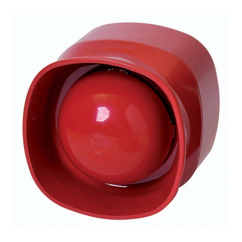
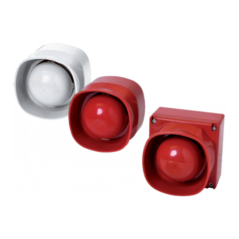
Bosch FNM-420V-A-WH User manual

Voice Sounder Indoor
FNM-420V-A-WH/RD
Installation Guide
deutsch
english
español
français
italiano
nederlands
polski
portuguese
türkçe


deutsch Inhaltsverzeichnis 6
english Table of contents 10
español Tabla de contenidos 14
français Table des matières 18
italiano Sommario 22
nederlands Inhoudsopgave 26
polski Spis treści 30
portuguese Índice 34
türkçe İçindekiler 38
Voice Sounder Indoor | 3
Bosch Sicherheitssysteme GmbH Installation Guide 03/2013 | 3.0 | F.01U.273.478

Graphics
FNM-420V-A-WH
FNM-420V-A-RD
5
3
2
1
6
4
4All | Graphics Voice Sounder Indoor
03/2013 | 3.0 | F.01U.273.478 Installation Guide Bosch Sicherheitssysteme GmbH

a2 a1 b2 b1 0V +U
LSN in
b1
a1
b2
LSN out a2
Xx
x
x X x
xx
X
A = 000
A = 001
- 254
A = CL00
LSN improved version
LSN classic
LSN improved version
Manual addressing
_____________________________________________________________________
13
0786 - CPD - 21249
EN 54-3:2001/A1:2002/A2:2006; EN 54-17:2005
Akustischer Signalgeber | Alarm Devices Sounder
Typ A: für Anwendungen in Gebäuden | Type A: for indoor use
FNM-420V-A-WH | FNM-420V-A-RD
Voice Sounder Indoor Graphics | All 5
Bosch Sicherheitssysteme GmbH Installation Guide 03/2013 | 3.0 | F.01U.273.478

Hinweise
i
Hinweis!
Die Installation darf nur von autorisiertem Fachpersonal durch-
geführt werden.
!
Vorsicht!
Die Produkte sollten nur an Orten ohne direkte Sonneneinstrah-
lung montiert werden, da nur so eine einwandfreie Funktionali-
tät und lange Lebensdauer sichergestellt werden kann.
i
Hinweis!
Die Batterie ist nicht im Lieferumfang inbegriffen und muss sep-
arat bestellt werden.
i
Hinweis!
Batterien dürfen nicht im Hausmüll entsorgt werden. Bitte ge-
ben Sie verbrauchte Batterien an den lokalen Sammelstellen ab.
Weitere Informationen finden Sie unter www.boschsecuri-
ty.com/standards.
i
Hinweis!
Dieses Produkt ist nur für die Wandmontage vorgesehen.
!
Warnung!
Eine gleichzeitige Verbindung mit einer LSN-Ringleitung und ei-
nem USB-Anschluss kann zu Schäden an Gerät, Zentrale und
Computer führen. Bevor Sie das Gerät mit einem USB-Ans-
chluss verbinden, trennen Sie es von der LSN-Ringleitung.
1
6de | Hinweise Voice Sounder Indoor
03/2013 | 3.0 | F.01U.273.478 Installation Guide Bosch Sicherheitssysteme GmbH

i
Hinweis!
Die 28 vorprogrammierten Signale können in der Programmier-
software FSP-5000-RPS ausgewählt werden.
Mithilfe der Konfigurationssoftware können individuelle Signale
unter Verwendung bestehender Tonarten und Sprachmeldun-
gen programmiert werden.
i
Hinweis!
Geräte mit der Einstellung LSN improved und gleichem Signal
können innerhalb einer Alarmgruppe synchronisiert werden.
Geräte mit unterschiedlichen LSN-Einstellungen (classic und
improved) können nicht innerhalb einer Alarmgruppe synchroni-
siert werden. In einem LSN-Ring können Alarmgruppen mit LSN
improved und Alarmgruppen mit LSN classic gemischt werden.
Nicht synchronisierte Geräte können nur in Bereichen installiert
werden, in denen sie nicht mit anderen Geräten akustisch inter-
agieren.
i
Hinweis!
Für eine Anwendung der zertifizierten Töne konform zu EN 54-3
müssen die Signalgeber mit maximaler Lautstärke betrieben
werden.
Lautstärkemessergebnisse der zertifizierten Töne sind im Doku-
ment Bulletin_Sound_Pressure_Level_EN54-3.pdf (F.01U.
283.373) aufgeführt. Das Dokument kann beim Hersteller ange-
fordert werden.
Montage
Siehe Graphics, Seite 4.
2
Voice Sounder Indoor Hinweise | de 7
Bosch Sicherheitssysteme GmbH Installation Guide 03/2013 | 3.0 | F.01U.273.478

1. Öffnen Sie den Signalgeber-Innenbereich mit dem
mitgelieferten Werkzeug (1). Drücken Sie die Spitzen des
Werkzeugs in die dafür vorgesehenen Öffnungen am
Gehäuse.
2. Bohren Sie die erforderlichen Löcher (2) auf der
Gehäuserückseite, und führen Sie die Kabel in das
Gehäuse.
3. Montieren Sie die Gehäuserückseite über die vorgestanzten
bzw. vorhandenen Bohrungen (3) mit mindestens zwei
Schrauben auf ebenem, trockenem Grund.
4. Verdrahten Sie die den Signalgeber mithilfe der
Klemmenleiste.
5. Für eine unterbrechungsfreie Alarmierung setzen Sie die
Batterie in die Batteriehalterung (4) ein, und schließen Sie
sie an. Stecken Sie hierfür den losen Batteriestecker bis
zum Anschlag in die vorgesehene Buchse (5).
6. Schließen Sie das Gehäuse, indem Sie den Signalgeber in
die Schnapphaken einrasten lassen bzw. den Signalgeber
mit den vier Schrauben (6) befestigen.
Konfiguration
Sie können die Sprachmeldungen und Signale mithilfe der
FNM-420V Konfigurationssoftware anpassen.
Die Software kann aus dem Onlinekatalog unter
www.boschsecurity.com heruntergeladen werden.
Systemanforderungen: Windows 7.
Die Anleitung zur FNM-420V Konfigurationssoftware, die eine
ausführliche Beschreibung der Software und der
Programmierung der Signalgeber enthält, steht ebenfalls unter
www.boschsecurity.com zum Download zur Verfügung.
3
8de | Hinweise Voice Sounder Indoor
03/2013 | 3.0 | F.01U.273.478 Installation Guide Bosch Sicherheitssysteme GmbH

Technische Daten
FNM-420V-A-RD/
FNM-420V-A-WH
Betriebsspannung 15 – 33V DC
Stromaufnahme
– Ruhe < 2,3 mA
– Alarm ≤ 15 mA
Max. Leistungsaufnahme 0,495 W
Anschlüsse 0,6 mm2 bis 2,5 mm2
Abmessungen (H x B x T) 105 x 105 x 95 mm
Gehäusematerial Kunststoff, ABS
Gehäusefarbe Rot, ähnlich zu RAL 3001;
weiß, RAL 9003
Gewicht ca. 295 g
Zulässige Einsatztemperatur -10 ℃ bis +55 ℃
Zulässige Lagertemperatur -25 ℃ bis +85 ℃
Relative Luftfeuchtigkeit Max. 95 %, nicht kondensierend
Schutzart nach EN 60529 IP42
Max. Schalldruckpegel in
1 m Entfernung
95,4 dB(A)
Frequenzbereich 440 Hz bis 2,90 kHz
Schnittstelle USB, mini-B
4
Voice Sounder Indoor Hinweise | de 9
Bosch Sicherheitssysteme GmbH Installation Guide 03/2013 | 3.0 | F.01U.273.478

Notices
i
Notice!
Installation must only be carried out by authorized specialist
personnel.
!
Caution!
The products should only be assembled out of direct sunlight,
as this is the only way to ensure correct functioning and a long
service life.
i
Notice!
The battery is not included in delivery and must be ordered sep-
arately.
i
Notice!
Batteries must not be disposed of in household waste. Please
take used batteries to the local collection points. See
www.boschsecurity.com/standards for further information.
i
Notice!
The product is to be used for wall mounting only.
!
Warning!
Concurrent connection with the LSN loop and an USB port may
cause damage to the device, panel and computer. Disconnect
the device from the LSN loop before the device is connected
through an USB port.
1
10 en | Notices Voice Sounder Indoor
03/2013 | 3.0 | F.01U.273.478 Installation Guide Bosch Sicherheitssysteme GmbH

i
Notice!
The 28 pregrogrammed signals can be selected in the
FSP-5000-RPS programming software.
With the Configuration Software individual signals can be pro-
grammed using the provided tone types and the provided voice
messages.
i
Notice!
Devices with LSN improved setting and same signal can be
synchronized within one alarm group. Devices with different
LSN settings (classic and improved) cannot be synchronized
within one alarm group. In one LSN loop, LSN improved and
LSN classic alarm groups can be mixed.
Not synchronized devices may only be installed in positions
where they do not interact acoustically with other devices.
i
Notice!
Only if the sounder volume is set to the maximum level, the cer-
tified signals comply with EN54-3.
Certified sound measurements are listed in the document Bulle-
tin_Sound_Pressure_Level_EN54-3.pdf (F.01U.283.373), which
can be obtained from the manufacturer.
Installation
See Graphics, page 4.
1. Open the Sounder Indoor using the tool supplied (1). Press
the point of the tool into the openings provided for it on
the housing.
2. Drill the required holes (2) on the rear side of the housing
and feed the cable into the housing.
2
Voice Sounder Indoor Notices | en 11
Bosch Sicherheitssysteme GmbH Installation Guide 03/2013 | 3.0 | F.01U.273.478

3. Fit the rear of the housing on a level, dry surface using the
pre-punched and/or any existing bore holes (3) and a
minimum of two screws.
4. Wire up the sounder using the terminal block.
5. For uninterruptible alarm signalling insert the battery into
the battery holder (4) and connect the battery. Push the
loose battery plug into the specified bushing (5) as far as it
will go.
6. Close the housing by clicking the sounder into place in the
snap-fit hooks or fastening the sounder in place with the
four screws (6).
Configuration
You can customize and program the voice messages and signals
using the FNM-420V Configuration Software.
The software can be downloaded from the online catalogue at
www.boschsecurity.com.
System requirements: Windows 7.
The FNM-420V Software Configuration Guide describing the
software and the programming of the sounders in detail is also
available for download at www.boschsecurity.com.
Technical data
FNM-420V-A-RD /
FNM-420V-A-WH
Operating voltage 15 - 33 V DC
Current consumption
– Standby < 2.3 mA
– Alarm ≤ 15 mA
Max. power consumption 0.495 W
Connections 0.6 mm2 to 2.5 mm2
3
4
12 en | Notices Voice Sounder Indoor
03/2013 | 3.0 | F.01U.273.478 Installation Guide Bosch Sicherheitssysteme GmbH

FNM-420V-A-RD /
FNM-420V-A-WH
Dimensions (H x W x D) 105 x 105 x 95 mm
Housing material Plastic, ABS
Housing color Red, similar to RAL 3001;
white, RAL 9003
Weight Approx. 295 g
Permissible operating
temperature
-10℃ to +55℃
Permissible storage
temperature
-25℃ to +85℃
Relative humidity Max. 95%, non-condensated
Protection category
according to EN 60529
IP42
Max. sound pressure level at
a distance of 1 m
95.4 dB(A)
Frequency range 440 Hz to 2.90 kHz
Interface USB, mini-B
Voice Sounder Indoor Notices | en 13
Bosch Sicherheitssysteme GmbH Installation Guide 03/2013 | 3.0 | F.01U.273.478

Notas
i
Nota!
La instalación debe realizarla exclusivamente personal autoriza-
do y especializado.
!
Precaución!
Los productos no deben exponerse directamente a la luz del
sol. Esta es la única forma de garantizar un funcionamiento cor-
recto y una larga vida útil.
i
Nota!
La batería no está incluida en el envío y hay que pedirla por
separado.
i
Nota!
Las baterías no deben desecharse junto con la basura domésti-
ca. Lleve dichas baterías a los puntos de recogida locales. Con-
sulte www.boschsecurity.com/standards para obtener más in-
formación.
i
Nota!
Este producto solo debe usarse para el montaje en pared.
!
Aviso!
Las conexiones simultáneas con un lazo LSN y un puerto USB
pueden causar daños en el dispositivo, la central y el ordena-
dor. Desconecte el dispositivo del lazo LSN antes de conectarlo
a un puerto USB.
1
14 es | Notas Voice Sounder Indoor
03/2013 | 3.0 | F.01U.273.478 Installation Guide Bosch Sicherheitssysteme GmbH

i
Nota!
Las señales preprogramadas 28 se pueden seleccionar en el
software de programación FSP-5000-RPS.
Las señales individuales se pueden programar con el software
de configuración con los tipos de tono y los mensajes de voz
suministrados.
i
Nota!
Los dispositivos con ajuste LSN improved y con la misma señal
pueden sincronizarse dentro de un mismo grupo de alarmas.
Los dispositivos con diferentes ajustes de LSN (clásico e im-
proved) no se pueden sincronizar dentro de un mismo grupo de
alarmas. En un lazo LSN se pueden mezclar grupos de alarmas
de LSN improved y LSN clásico.
Los dispositivos no sincronizados sólo pueden instalarse en
posiciones en las que no interactúen acústicamente con otros
dispositivos.
i
Nota!
Las señales certificadas sólo cumplen con la norma EN54-3 si el
volumen de la sirena está ajustado al nivel máximo.
En el documento Bulletin_Sound_Pressure_Level_EN54-3.pdf (F.
01U.283.373), que puede solicitarse al fabricante, hay una lista
de las mediciones de sonido certificadas.
Instalación
Consulte Graphics, Página 4.
1. Abra la sirena para interior con la herramienta suministrada
(1). Para esto, presione con la punta de la herramienta
sobre los orificios de la carcasa.
2. Taladre los orificios necesarios (2) en la parte posterior de
la carcasa y pase los cables a través de ella.
2
Voice Sounder Indoor Notas | es 15
Bosch Sicherheitssysteme GmbH Installation Guide 03/2013 | 3.0 | F.01U.273.478

3. Coloque la parte posterior de la carcasa en una superficie
nivelada y seca utilizando los orificios pretaladrados o
cualquier otro orificio (3) y, como mínimo, dos tornillos.
4. Conecte los cables de la sirena mediante el bloque de
terminales.
5. Para obtener una señal de alarma ininterrumpida, coloque
la batería en su soporte (4) y conéctela. Inserte el enchufe
suelto de la batería en el casquillo indicado (5) hasta el
tope.
6. Cierre la carcasa encajando la sirena en los ganchos de
ajuste hasta que oiga un "clic" o bien fije la sirena con los
cuatro tornillos (6).
Configuración
Puede personalizar y programar los mensajes de voz y las
señales con el software de configuración de la FNM-420V.
El software se puede descargar del catálogo en línea en
www.boschsecurity.com.
Requisitos del sistema: Windows 7.
La guía del software de configuración de la FNM-420V que
describe al detalle el software y el proceso de programación de
las sirenas también se puede descargar en
www.boschsecurity.com.
Datos técnicos
FNM-420V-A-RD /
FNM-420V-A-WH
Tensión en funcionamiento 15 - 33V de CC
Consumo de corriente
– En reposo < 2,3 mA
– Alarma ≤ 15 mA
Consumo de energía máx. 0,495 W
3
4
16 es | Notas Voice Sounder Indoor
03/2013 | 3.0 | F.01U.273.478 Installation Guide Bosch Sicherheitssysteme GmbH

FNM-420V-A-RD /
FNM-420V-A-WH
Conexiones De 0,6 mm2 a 2,5 mm2
Dimensiones (Al. x An. x Pr.) 105 x 105 x 95 mm
Material de la carcasa Plástico, ABS
Color de la carcasa Rojo, similar a RAL 3001;
blanco, RAL 9003
Peso Aprox. 295 g
Temperatura de
funcionamiento permitida
De -10℃ a +55℃
Temperatura de
almacenamiento permitida
De -25℃ a +85℃
Humedad relativa Máx. 95%, sin condensación
Categoría de protección
conforme a EN 60529
IP42
Nivel de presión acústica
máxima a una distancia de
1 m
95,4 dB(A)
Rango de frecuencia De 440 Hz a 2,90 kHz
Módulo USB, mini-B
Voice Sounder Indoor Notas | es 17
Bosch Sicherheitssysteme GmbH Installation Guide 03/2013 | 3.0 | F.01U.273.478

Remarque
i
Remarque!
L'installation doit être réalisée uniquement par un employé spé-
cialisé et habilité.
!
Attention!
Les produits ne doivent pas être montés à la lumière directe du
soleil ; c'est le seul moyen de garantir un fonctionnement cor-
rect et une durée de vie élevée.
i
Remarque!
La batterie n'est pas fournie et doit être commandée séparé-
ment.
i
Remarque!
Les batteries ne peuvent être jetées avec les ordures ménag-
ères. Veuillez rapporter les batteries aux points de collecte lo-
caux. Pour plus d'informations, consultez le site www.boschse-
curity.com/standards.
i
Remarque!
Le produit est destiné exclusivement à un montage mural.
!
Avertissement!
La connexion simultanée à la boucle LSN et au port USB peut
conduire à l'endommagement de l'appareil, de la centrale ou de
l'ordinateur. Déconnectez l'appareil de la boucle LSN avant de
le connecter à un port USB.
1
18 fr | Remarque Voice Sounder Indoor
03/2013 | 3.0 | F.01U.273.478 Installation Guide Bosch Sicherheitssysteme GmbH

i
Remarque!
Les 28 signaux préprogrammés sont disponibles dans le logiciel
de programmation FSP-5000-RPS.
Dans le logiciel de configuration, vous pouvez configurer les sig-
naux à l'aide des types de tonalité et des messages vocaux four-
nis.
i
Remarque!
Des périphériques pourvus de paramètres LSN improved et du
même signal peuvent être synchronisés au sein d'un même
groupe d'alarme. Des périphériques avec des paramètres LSN
différents (classic et improved) ne peuvent pas être synchroni-
sés au sein d'un même groupe d'alarme. Dans une boucle LSN,
les groupes d'alarme LSN improved et LSN classic peuvent être
mélangés.
Des périphériques non synchronisés peuvent être installés, à
condition qu'il n'y ait pas d'interaction acoustique avec d'autres
périphériques.
i
Remarque!
Les sons homologués sont conformes à la norme EN 54-3
uniquement si le volume de la sirène est réglé sur le maximum.
Les mesures de son homologué figurent dans le document Bul-
letin_Sound_Pressure_Level_EN54-3.pdf (F.01U.283.373) dis-
ponible auprès du fabricant.
Installation
Voir Graphics, Page 4.
1. Ouvrez la sirène intérieure à l'aide de l'outil fourni (1).
Appuyez la pointe de l'outil dans les ouvertures prévues à
cet effet sur le boîtier.
2
Voice Sounder Indoor Remarque | fr 19
Bosch Sicherheitssysteme GmbH Installation Guide 03/2013 | 3.0 | F.01U.273.478

2. Percez les trous adéquats (2) à l'arrière du boîtier et faites
passer le câble dans le boîtier.
3. Fixez l'arrière du boîtier sur une surface sèche et plate à
l'aide des trous de fixation (3) prédécoupés ou des trous
existants et au moins deux vis.
4. Câblez la sirène à l'aide du bornier.
5. Pour une signalisation d'alarme sans coupure, insérez la
batterie dans le compartiment à batterie (4) et branchez la
batterie. Poussez la fiche de batterie libre jusqu'en butée
dans le passe-câble indiqué (5).
6. Fermez le boîtier en enclenchant la sirène dans les crochets
encliquetables ou en fixant la sirène à l'aide de quatre vis
(6).
Configuration
Vous pouvez personnaliser et programmer les messages vocaux
et les signaux en utilisant le logiciel de configuration FNM-420V.
Vous pouvez télécharger le logiciel depuis le catalogue en ligne
sur www.boschsecurity.fr.
Configuration minimale requise : Windows 7.
Vous pouvez également télécharger le guide de configuration du
logiciel FNM-420V décrivant en détail le logiciel et la
programmation des sirènes sur www.boschsecurity.fr.
Caractéristiques techniques
FNM-420V-A-RD /
FNM-420V-A-WH
Tension de fonctionnement 15- 33 V DC
Consommation
– Veille < 2,3 mA
– Alarme ≤ 15 mA
Consommation maximale 0,495 W
3
4
20 fr | Remarque Voice Sounder Indoor
03/2013 | 3.0 | F.01U.273.478 Installation Guide Bosch Sicherheitssysteme GmbH
Other manuals for FNM-420V-A-WH
1
This manual suits for next models
1
Table of contents
Languages:
Other Bosch Marine Equipment manuals

Bosch
Bosch MSS 300 WH-EC Quick start guide

Bosch
Bosch FNM-420-A-BS-RD User manual

Bosch
Bosch FNM-420V-A-WH User manual

Bosch
Bosch Rexroth Marex SB User manual

Bosch
Bosch FNM-420-A-RD User manual

Bosch
Bosch FNM-320-SRD User manual

Bosch
Bosch FNM-420U-A-BSWH User manual
Bosch
Bosch FNM-420U-A-WH User manual

Bosch
Bosch FNM-420U-A-BSWH User manual

Bosch
Bosch FNM-320-SRD User manual