Automatic Systems TriLane TL Series User manual

TriLaneTLxx
www.automatic-systems.com
TRIPOD TURNSTILE
Technical Manual
(Translated from the original French version)
Rev. 04

p. 2/46
TLxx-MT-EN-04
DOCUMENT REVISION
Rev. Date Written by Checked by Purpose
00 Date JB / SL SD First edition.
01 24/01/2018 JB JB Electrical diagrams Rev B and TOF camera option
02 02/2019 JB JB Correction of weight according to datasheet
03 04/2019 JB SDA TL1 version included in the manual
04 09/07/2019 JB SDA New CE certificate and last modifications to include TL1
version.

p. 3/46
TLxx-MT-EN-04
DOCUMENT REVISION 2
TABLE OF CONTENTS 3
TABLE OF ILLUSTRATIONS 5
1. PRESENTATION 6
2. SAFETY WARNINGS 7
3. GENERAL SYMBOLS 8
4. INTRODUCTION 9
4.1. Terminology 9
4.2. idenTificaTion plaTe 10
4.3. convenTions 10
5. GENERAL DESCRIPTION 12
5.1. exTernal dimensions 12
5.2. operaTing modes 13
5.2.1. With power on 13
5.2.2. With power off 13
5.3. audible signal 13
5.4. visual symbols (funcTional picTograms) 14
5.5. space provided for reader inTegraTion 15
6. INSTALLATION INSTRUCTIONS 17
6.1. packaging 17
6.2. unpacking 17
6.3. swiTching on and off The equipmenT 17
6.4. general dimensions and insTallaTion plan 18
6.5. recommended Tools 20
6.6. preliminary work 20
6.6.1. Site preparation work 20
6.6.2. Installing the turnstile 20
6.6.3. Installing the stainless steel arm 21
6.6.4. Electrical connections and initial power-up 21
7. MECHANISM 22
7.1. operaTing principle 22
7.2. descripTion of The sTandard mechanism 23
7.2.1. Removing the cover 23
7.2.2. Overview of the kinematics 24
7.2.3. Locking and unlocking principle 24
7.2.4. Centring mechanism 25
7.2.5. Shock absorber 26
TABLE OF CONTENTS

p. 4/46
TLxx-MT-EN-04
7.2.6. Fixed arm turret assembly 26
7.3. descripTion of The oTher mechanical opTions 27
7.3.1. Dropping arm option 27
7.3.2. Motorisation option 28
7.3.3. TOF camera detection option 28
7.3.4. Other housing options 29
7.4. descripTion of The elecTronic assembly 30
7.4.1. Power supply circuit board 32
7.4.2. Electronic circuit board 32
7.4.3. Functional pictogram (operating symbols) 33
7.4.4. List of the electrical and electronic sub-assemblies 33
8. MAINTENANCE 34
8.1. firsT check afTer 50,000 passages 34
8.2. rouTine mainTenance 34
9. SETTINGS AND TECHNICAL INTERVENTIONS 36
9.1. faulT diagnosis 36
9.2. replacing componenTs 37
9.2.1. Replacing a fixed arm (barrier) 37
9.2.2. Replacing a dropping arm 37
9.2.3. Replacing the angle sensor assembly 38
9.2.4. Replacing or inverting the direction of an electro-magnet 38
9.2.5. Replacement of a gear motor (option) 39
9.2.6. Replacement of rings, washers, springs and other wear parts 40
9.2.7. Replacing a functional pictogram 40
10. TECHNICAL DATA 41
11. ELECTRICAL DIAGRAMS 42
12. EC DECLARATION OF CONFORMITY 45

p. 5/46
TLxx-MT-EN-04
TABLE OF ILLUSTRATIONS
Fig. 1 Conventions for direction A and direction B 10
Fig. 2 External dimensions, 2-leg TL2 version 12
Fig. 3 External dimensions, 1-leg TL1 version 12
Fig. 4 Functional pictogram option TL2 14
Fig. 5 Functional pictogram option TL1 14
Fig. 6 Space available under the TL2 hood for reader integration 15
Fig. 7 Space available under the TL1 hood for reader integration 16
Fig. 8 - Main switch 17
Fig. 9- TL2 general dimensions and installation drawing (plan CH9594) 18
Fig. 10 Fixing points TL1 version 18
Fig. 11 TL1 general dimensions and installation drawing 19
Fig. 12 - Removing the feet (TL2) 20
Fig. 13 - Installing the stainless steel arm 21
Fig. 14 Removing the cover. 23
Fig. 15 Access to the mechanism and electronic board (TL1) 23
Fig. 16 View of the kinematic assembly 24
Fig. 17 View of the locking/unlocking assembly 24
Fig. 18 Anti-noise spacer on the axis of the electro-magnets 25
Fig. 19 View of the centring mechanism 25
Fig. 20 Shock absorber option 26
Fig. 21 Fixed arm turret 26
Fig. 22 Dropping arm device 27
Fig. 23 Motorisation option 28
Fig. 24 TOF camera option on TL2 28
Fig. 25 Other housing options (TL2) 29
Fig. 26 Other housing options (TL1) 29
Fig. 27 Readers option 30
Fig. 28 General overview of the electrical and electronic panels 30
Fig. 29 Overview of the electronic plates (TL1) 31
Fig. 30 Motor control board position on the TL1 31
Fig. 31 Power supply circuit board 32
Fig. 32 Power supply plate on TL1 32
Fig. 33 Control circuit board 33
Fig. 34 Electronic circuit of the functional pictogram 33
Fig. 35 Fixing the dropping arm 38
Fig. 36 Angle sensor 38
Fig. 37 Electro-magnet 39
Fig. 38 Fixing the motor 39

p. 6/46
TLxx-MT-EN-04
1. PRESENTATION
You have chosen a TriLane equipment fitted with a tripod turnstile designed and manufactured by Automatic Systems, for
which we thank you. We are convinced that your acquisition will give you complete satisfaction for many years and, to
this end, invite you to read the following information carefully before installing your equipment.
While this manual has been prepared with great care, some information may seem erroneous or unclear to you. In that
case, please do not hesitate to contact us with your remarks or questions.
PRIOR WARNING
YOUR TRIPOD TURNSTILE IS MADE UP OF VARIOUS MECHANICAL
AND ELECTRICAL COMPONENTS. ANY NEGLIGENCE WHILE WORKING
ON IT COULD HAVE SERIOUS CONSEQUENCES FOR YOUR SAFETY.
DISCONNECT THE GENERAL POWER SUPPLY FROM THE EQUIPMENT AS
SOON AS YOU OPEN THE CASING. BE VERY CAREFUL WHEN HANDLING
ANY INTERNAL ELEMENTS THAT CAN BE TURNED ON OR ARE IN MOTION.

p. 7/46
TLxx-MT-EN-04
2. SAFETY WARNINGS
• This manual must be available to all persons required to work on the equipment: installers, maintenance operators,
end users, etc.
• This equipment is designed for pedestrian access control and is not to be used for another purpose without risk to
the user and to the integrity of the equipment.
• Automatic Systems cannot be held liable for damage resulting from improper use of the equipment.
• In particular, the equipment is not designed for:
-Persons with reduced mobility.
-Unaccompanied young children.
-Managing a continuous flow of more than 20 persons per minute.
• Do not install this equipment in an explosive area.
• Do not add non-original or non-approved accessories (contact between different metals causes a galvanic effect
that adversely affects the corrosion resistance of the equipment).
• The contractor shall comply with local regulations when installing the equipment.
• All operations on the equipment must be carried out by qualified personnel. Any work on this product that is
unauthorised or carried out by an unqualified technician will automatically void the manufacturer’s warranty.
• Access to the mechanism must be reserved for staff who are aware of the electrical and mechanical risks incurred
in case of negligent handling. These personnel are required to lock the access panels to the mechanism after the
intervention.
• As soon as the upper casing is opened for maintenance, cut off the power via the circuit breaker.
This manual details how the equipment works and provides information concerning fault diagnosis and maintenance
operations in order to ensure the device works at maximum efficiency. We recommend you read it carefully before starting
up the equipment.
Keep this manual in a safe place, at the disposal of the operating and maintenance personnel.

p. 8/46
TLxx-MT-EN-04
3. GENERAL SYMBOLS
The following symbols are used in this manual or as labels on the equipment:
This symbol is used to highlight a tip that may help you to better understand the product.
This symbol is used to highlight an important instruction for the correct use and/or maintenance of
the product.
This symbol is used to highlight a risk of electric shock or electrocution.
This symbol is used to highlight a risk of cutting yourself.
This symbol is used to identify the ground connection point.
(Either in the form of an affixed label or directly engraved on a mechanical part)
13
This symbol is used to indicate the tool to be used for the relevant operation.
This symbol indicates that the equipment conforms to European standards and directives.
This symbol indicates that the equipment must be disposed of in accordance with the applicable
European Directives (DEEE 2012/19/EU).

p. 9/46
TLxx-MT-EN-04
4. INTRODUCTION
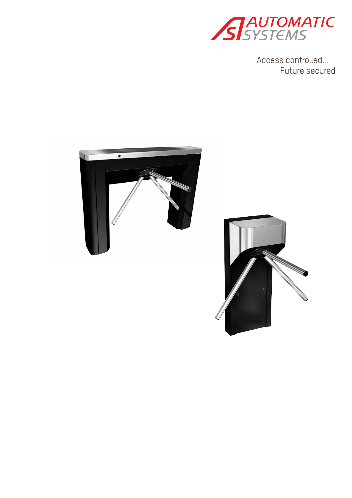
The tripod turnstiles in the TriLane range are designed for deterrent and economical access control, and allow the
incorporation of control equipment such as proximity readers, barcode scanners, badge collectors, etc. .
The assembly is finished to a level that ensures proper sealing and acoustic insulation from the surrounding environment.
The rotation control mechanism for the arms is the result of many years' experience in the development and manufacture
of access control equipment and the marketing of tens of thousands of units in all corners of the world.
The mechanical and electronic assembly is located in the central part of the tripod, under the protective cover, and
therefore out of reach for users; the connection and the fixation to the ground do not require any particular construction
work.
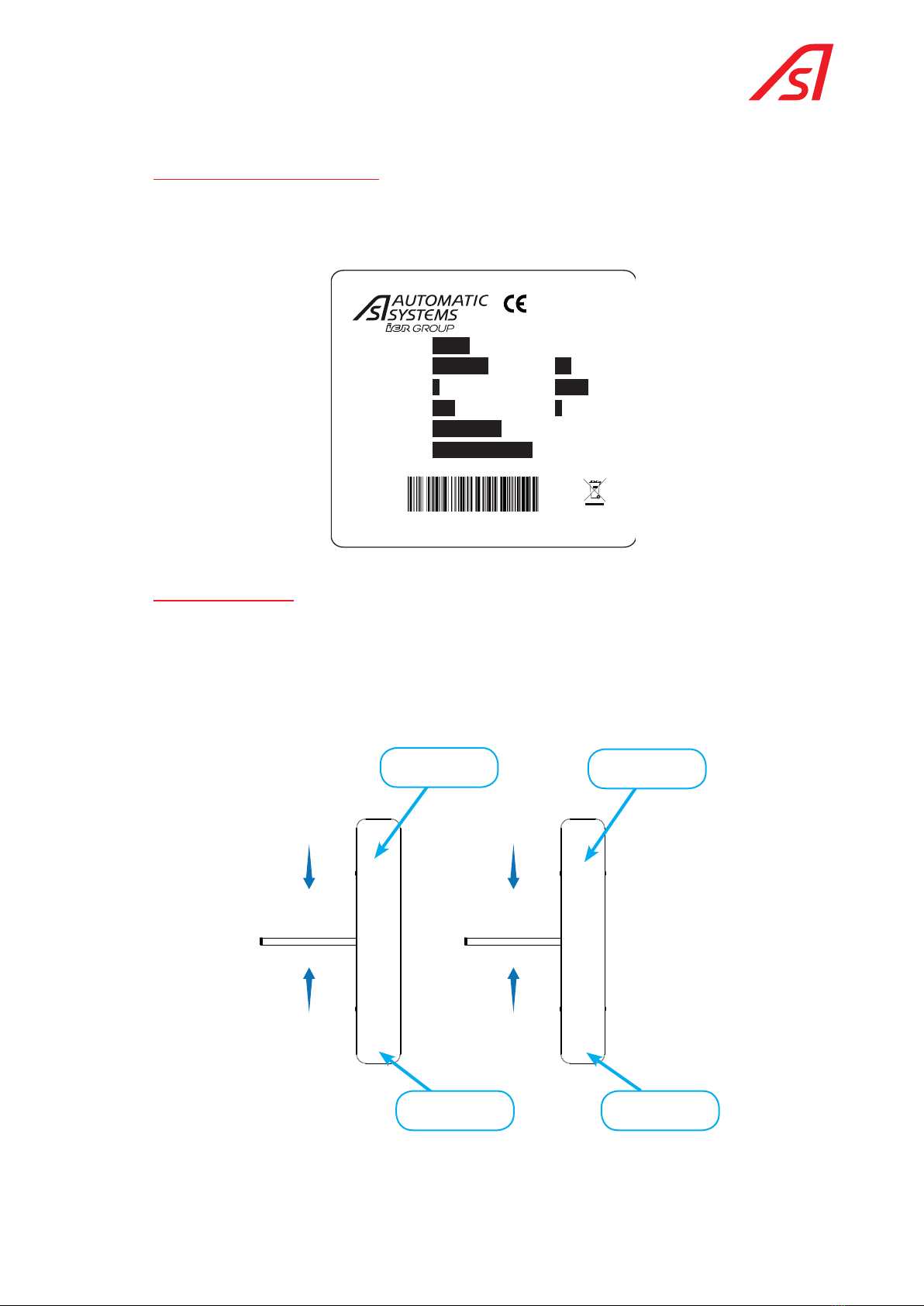
The mechanism, which has a robust and reliable design, can be integrated into two bodywork models:
• The compact version with single leg, called TL1 in this manual;
• The version with two legs, allowing easier integration of one or two readers, and called TL2 in this manual.
The design is nevertheless modular, because the same kinematic assembly is found in the TL1 and TL2 models.
Many configurations and options are available to cover all cases that are likely to be encountered in pedestrian access
control: functional pictograms, motorised movement, dropping arms, presence detection, full stainless steel finish...
4.1. TERMINOLOGY
AS Automatic Systems.
CMD Command
DI Digital input
DO Digital output
I/O Input / Output
O/S Out of service
HMI Man-Machine Interface
CRA Card reader direction A
CRB Card reader direction B
NC Normally closed(contact)
NO Normally open(contact)
OP Opening
MVT Movement
RGBW Red – Green – Blue - White
TL1 TriLane version with single leg
TL2 TriLane version with two legs
TOF TOF camera (Time of Fly): This camera calculates the time necessary for a light beam to be reflected
on each point of the object or user present in the passage, which gives a 3D representation and
enables a presence and its uniqueness to be checked to a good approximation.
TOR All or nothing
Direction A By convention, direction A is the passage from the uncontrolled area to the controlled area.
Direction B Passage in opposite direction to direction A
Direction B corresponds to passing from the controlled area to the uncontrolled area.
ZC Controlled area
ZNC Uncontrolled area
ZCZNC Direction from the controlled area to the uncontrolled area

p. 10/46
TLxx-MT-EN-04
ZNCZC Direction from the uncontrolled area to the controlled area
4.2. IDENTIFICATION PLATE
The name plate, an example of which is given below, contains technical information regarding the characteristics of the
equipment and its date of manufacture.
The serial number of the equipment is useful in the event of a technical support request.
Model
Mfg Date
Phases
Volts
kg
Hz
A
Item
Serial
SN
MADE IN BELGIUM
www.automatic-systems.com
TL2P
xx/xx/18
230
E/TL2P/002
18-TL2P-B0000
1
2
65
50/60
4.3. CONVENTIONS
The figure below illustrates what is meant by passage in directions A and B. The optional reader, which is always placed
to the right of the passage in direction A, will generally be incorporated under the cover of the TriLane in the uncontrolled
area.
The optional reader in direction B (exit direction) will generally be placed inside the same housing, even when a battery of
several TriLane is installed, in order to avoid connections between housings and installing an additional equipment at the
end of the battery. However, other layouts are possible on request.
A
B
Controlled area
Non controlled area
A
B
Controlled area
Non controlled area
Possible reader
direction A
Possible reader
direction B
Possible reader
direction B
Possible reader
direction A
Fig. 1 Conventions for direction A and direction B

p. 11/46
TLxx-MT-EN-04
The TriLane turnstile can be configured in 5 operating modes in each direction of passage. Some modes have an impact
on the assembly of the kinematic assembly, and the desired configuration should therefore be specified when ordering
the product.
Code Description Comment
1 Access always free. The locking mechanism is not installed
2 Access always blocked The locking mechanism is present, but without
electro-magnet
3 Access always blocked when power is on,
and free when power is off.
The lock and the electro-magnet are present.
4 Access controlled electrically and
blocked when power is off.
The lock and the electro-magnet are present.
5Access controlled electrically and free
when power is off.
The lock and the electromagnet are present.
So, for example, a TriLane A5/B1 will be controlled in the A (entry) direction and always be free in the B (exit) direction. This
is the ex-factory configuration if nothing else is specified in the customer’s order.

p. 12/46
TLxx-MT-EN-04
5. GENERAL DESCRIPTION
5.1. EXTERNAL DIMENSIONS
1300
=
880
=
210210
5 0920
510
750
235
Fig. 2 External dimensions, 2-leg TL2 version
400
100
750
977
338.5 510
Fig. 3 External dimensions, 1-leg TL1 version

p. 13/46
TLxx-MT-EN-04
5.2. OPERATING MODES
5.2.1. With poWer on
The TriLane, which is fitted with an optional detection system, has two operating modes when power is on:
Mode Description
NF (Normally closed) At rest and in controlled mode, the passage is locked until a user obtains a passage
authorisation. The passage is then unlocked to perform a cycle in the authorised
direction.
NO (Normally Open) At rest and in the controlled mode, the passage is unlocked. The lock will be actuated if
the system detects a turret rotation without passage authorisation.
This mode is only of interest if the electro-magnet has to be powered to lock the turret
(which is the case in the NO configuration with power off). There will be energy saving in
a rest state.
5.2.2. With poWer off
When power is off, the unit can be configured as normally open (NO) or normally closed (NC). This setting depends on
the physical orientation of the solenoid coil, as they have an internal return spring The control of the electro-magnets
will therefore be different in each case, and a configuration parameter is provided in the memory of the AS1635 logic.
5.3. AUDIBLE SIGNAL
The buzzer, which is present on the AS1635 logic board, can be activated in 2 cases:
Case Buzzer signal (factory setting)
Intrusion Continuous sound
Fraud Rapid intermittent (with detection option)
The operation of the buzzer can be changed by a parameter change on the AS1635 control circuit board. For details, refer
to the technical manual of the AS1635, in the section on configuration parameters.

p. 14/46
TLxx-MT-EN-04
5.4. VISUAL SYMBOLS (FUNCTIONAL PICTOGRAMS)
In order to correctly orient users in obtaining a right of passage, functional pictograms are to be provided in each direction
of passage (optional).
In this case, the upper part of the cover has two cut-outs that allow the placement of opal-coloured Plexiglass. These
diffuse the light emitted by a set of LEDs of different colours (WBGR for White/Blue/Green/Red).
Operating symbols
(functional pictograms)
Fig. 4 Functional pictogram option TL2
Operating symbols
(functional pictograms)
Fig. 5 Functional pictogram option TL1

p. 15/46
TLxx-MT-EN-04
The following are the colour conventions in the factory configuration according to the status of the TriLane:
Case Colour Flashing
Power on Red No
Initialisation Blue No
Evacuation Green Yes
Maintenance Orange No
Not used (free) Green No
Forbidden Red No
Controlled pending validation White No
Controlled with authorised passage. Green No
Controlled without right of passage request. Red No
5.5. SPACE PROVIDED FOR READER INTEGRATION
The upper inner part of each leg is available for integration of a reader. A plastic support, fixed on two studs, is available
as an option. Between 175 mm and 210 mm are available in the length direction. If this volume is insufficient, a cut-out in
the closing plate between the leg and the central part is also possible (study available on request).
The other dimensions are shown in the figure below.
Where necessary (to save significant space in the height direction), the reinforcing bar welded to the end of the leg can
be cut.
This reinforcing bar can be
cut out if necessary
Fig. 6 Space available under the TL2 hood for reader integration

p. 16/46
TLxx-MT-EN-04
Fig. 7 Space available under the TL1 hood for reader integration

p. 17/46
TLxx-MT-EN-04
6. INSTALLATION INSTRUCTIONS
6.1. PACKAGING
In most cases, your turnstile will be delivered in a cardboard box attached to a wooden pallet.
A plastic bag containing the keys and attachments for the last arm is attached to one of the turnstile arms.
The last arm is located inside the turnstile, under the cover.
6.2. UNPACKING
When the equipment arrives on-site, please check that it is complete and in good condition.
If for some reason damage has occurred during transport, please check that the problem is described in the transport
document and, where necessary, report the incident to Automatic Systems for corrective actions.
6.3. SWITCHING ON AND OFF THE EQUIPMENT
OFF
Fig. 8 - Main switch
Ifyou open the housIng, turn off the power supply by swItchIng off the maIn swItch (see fIg. 8) on the left-hand
cIrcuIt board whIch Is accessIble vIa the cover on the tl2 and vIa the front panel on the tl1.

p. 18/46
TLxx-MT-EN-04
6.4. GENERAL DIMENSIONS AND INSTALLATION PLAN
With the TL2 housing, the power and data cables can be insert inside the housing through the right or left end box. But we
recommend a connection through the left (B) side considering that the main circuit breaker is located to the left.
min. 100*
AAA
BBB
Ø60
Ø15*
160 37.537.5
235550235235
40
1300
754
880 210210
550
80
Power supply and connection wiring inlet, can be through right or left end box
EXPANSIBLE ANCHOR B15/30
-/3413/000
(Suggested reference (M10))
Ø 60 mm PVC SHEATH.Concrete
Wiring to provide for:
230 V single phase power supply + ground, in 3G2.5 ²
IP CABLE (Ethernet) STP CAT.5
* Dimensions according to standard Automatic Systems anchoring.
Fig. 9- TL2 general dimensions and installation drawing (plan CH9594)
340
Oblong hole 12 x 15 mm
Oblong hole
46 x 106 mm
for connecting
cables
Expansible anchor
M10
to provide
Fig. 10 Fixing points TL1 version

p. 19/46
TLxx-MT-EN-04
DESIGNATION :
BESTEMMING :
DESSINE :
GETEKEND :
DATE :
DATUM :
N° DOSSIER :
N° DOSSIER :
VERIFIE :
NAGEZIEN :
ECHELLE :
SCHAAL :
PLAN N° :
PLAN N° :
Ce plan est notre propriété et ne peut être cédé à des tiers ni être recopié sans autorisation écrite de Automatic Systems.
Dit plan blijft onze eigendom en mag niet voorgelegd aan derden noch worden gekopieerd zonder schriftelijke toelating van Automatic Systems.
TRILANE TL001
CF 20/03/2019 -----
----- 1/20 CH9761
Ne pas mesurer sur le plan.
Niet meten op het plan.
Les dimensions sont données
en mm.
De afmetingen zijn gegeven in
mm.
A3
Avenue Mercator. 5 - B-1300 Wavre
www.automatic-systems.com
60
48
350
30340
30
==
970
TUYAU EN PVC Ø 60
BUIS IN PVC Ø 60
TUBE IN PVC Ø 60
LEERROHR Ø60
BETON
CONCRETE BASE
FUNDAMENT
ALIMENTATION 230V MONO+TERRE EN 3G2.5²
CABLE IP (Ethernet) STP CAT.5
VOEDING 230V MONO + AARDE, IN 3G2.5 ²
KABEL IP (Ethernet) STP CAT.5
POWER SUPPLY SINGLE PHASE 230V MONO + T, IN 3G2.5 ²
IP CABLE (Ethernet) STP CAT.5
SPANNUNGSVERSORGUNG 230V EINPHASIG + ERDE, 3X2,5 ²
KABEL NETZWERK (Ethernet) STP CAT.5
ZONE D'ARRIVEE DES CABLES D'ALIMENTATION ET DE COMMANDE
AAMKOMST VOEDINGSKABELS EN VERBINDINGSKABELS
POWER SUPPLY AND CONNECTION WIRING INLET
BEREICH FÜR KABELZUFÜHRUNG FÜR SPANNUNGS- UND STEUERLEITUNGEN
A
B
fixations
750
40510
550
400350
Fig. 11 TL1 general dimensions and installation drawing

p. 20/46
TLxx-MT-EN-04
6.5. RECOMMENDED TOOLS
13
• Standard electrical tools.
• Flat spanner set.
• Set of Allen keys.
• Spirit level.
• Hammer drill + concrete drill bit - Ø 15 x 100
• Standard protective equipment: gloves, goggles, hard hat and safety shoes.
6.6. PRELIMINARY WORK
• The turnstile has been specially packaged for transport. Bring the material to the installation site with the help of
a forklift truck and remove the packing material.
• Unlock the cover and open it (TL2) or the front panel (TL1). The keys are supplied as accessories in a separate bag.
• Lift and remove the 2 feet (TL2) and the top cover (TL1).
4:3 4:2
Fig. 12 - Removing the feet (TL2)
• Check the condition of the material - although it has been carefully packed, damage may have occurred during
transport.
6.6.1. Site preparation Work
This is basically the following:
• Study the set-up and positioning of the equipment according to the general layout of the site.
• Prepare the holes in the floor according to the specifications of the installation drawing.
• Be sure to drill the holes with a diameter suitable for the expandable dowels that you are going to use (recommended
type: model B15/30, ref. -/3413/000).
• Check the correct location of the cable passage according to the installation drawing. .
• Prepare the passage for the electrical control cables of the Central Controller Station (not supplied) and the mains
supply cables (230V single-phase + earth, i.e. 3G x 2.5). Provide 1.5 metres extra.
If you add any elements to the feet of the turnstile that could ignite (see EN60950 standard, paragraph 4.4.5), ensure that
the installation surface is non-flammable.
6.6.2. inStalling the turnStile
• Position the turnstile precisely.
This manual suits for next models
2
Table of contents
Other Automatic Systems Turnstile manuals

Automatic Systems
Automatic Systems TR450 User manual

Automatic Systems
Automatic Systems SmartLane User manual

Automatic Systems
Automatic Systems TR491 User manual

Automatic Systems
Automatic Systems TriLane TL2 User manual

Automatic Systems
Automatic Systems SL930 User manual

Automatic Systems
Automatic Systems SMARTLANE SL 90X User manual

Automatic Systems
Automatic Systems SMARTLANE SL 90 Series User manual

Automatic Systems
Automatic Systems TriLane TL1 User manual