C-19
Economical Door Side Sensor
(A)
Photoelectric
Sensors
(B)
Fiber
Optic
Sensors
(C)
Door/Area
Sensors
(D)
Proximity
Sensors
(E)
Pressure
Sensors
(F)
Rotary
Encoders
(G)
Connectors/
Sockets
(H)
Temperature
Controllers
(I)
SSRs / Power
Controllers
(J)
Counters
(K)
Timers
(L)
Panel
Meters
(M)
Tacho /
Speed / Pulse
Meters
(N)
Display
Units
(O)
Sensor
Controllers
(P)
Switching
Mode Power
Supplies
(Q)
Stepper Motors
& Drivers
& Controllers
(R)
Graphic/
Logic
Panels
(S)
Field
Network
Devices
(T)
Software
2. Mount sensor heads to the mounting holes.
When not using the bracket
① One push method
• Put the sensor head into the mounting hole as the gure.
※Check the nuts are fixed on the sensor body tightly.
※Install the sensor with no gap between the nut and the
side of the door (or panel).
② Screw method
• Put the sensor head to the mounting hole.
※Install the sensor with no gap between the panel and the
sensor.
② Screw method
• Remove the nut and head holder from the sensor head.
• Install the sensor head to the bracket.
• Fix the bracket on the side post of the door by screws.
※It may cause malfunction because sensitivity setting
is not available as the optical axes are not matched if
sensor body is inclined.
※Check the damage such as scratches or pollutant on the
lens of the sensor head. It may cause malfunction in the
condition of interrupted light or lack of sensitivity by dust.
When using the bracket
① One push method
• Put the sensor head to the bracket.
• Fix the bracket to the desired place by screws.
※Check the nut is xed to the sensor body tightly.
※Install the sensor with no gap between the nut and the
side of the door (or bracket).
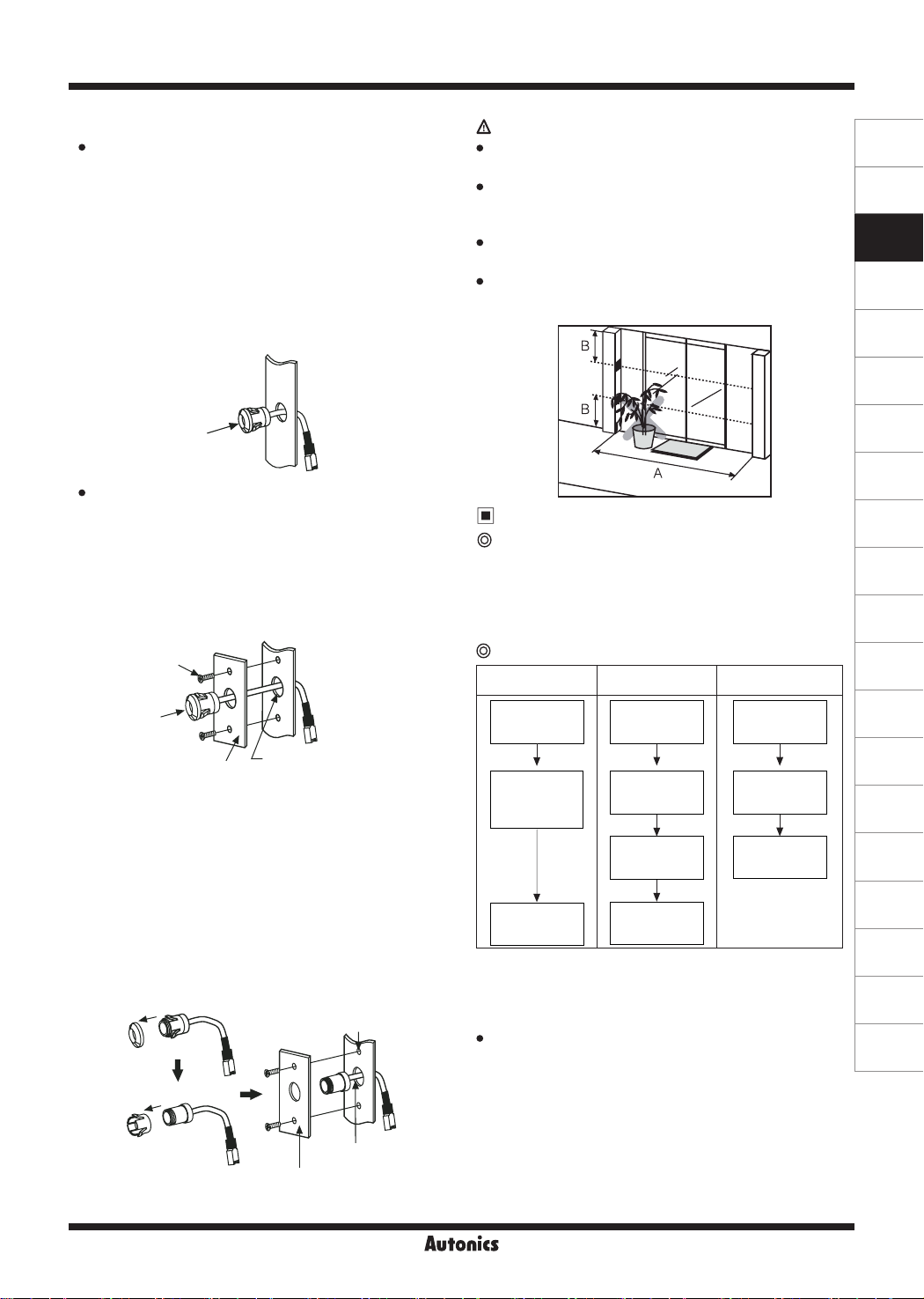
Caution for sensor installation
The rated sensing distance is 10m (A).Install the sensors
within the rated sensing distance.
Install the sensor with more than 50cm (B) gap from the
bottom and ceiling. It may cause malfunction by reected
beams from the surface of the bottom and ceiling.
Do not put obstacles between Emitter and Receiver, or it
may cause malfunction.
This product is for indoor. Avoid the place where
exposed in direct sunlight or it is in over rated intensity of
illumination.
M4 at head
screw
Bracket Through hole for sensor head
: Ø13 to 14mm
Screw hole
: M4 Tap or Ø3.5mm
Through hole for sen-
sor head
Ø13 to 14mm
Bracket
Nut
①
②
Head holder
Sensitivity Setting
Sensitivity setting is required when a user installs this unit
at rst or there is malfunction due to lack of sensitivity.
Depending on the sensing distance, the controller
automatically sets the optimum sensitivity for the best
operation.
Check the followings when sensitivity setting is
failed.
①Check there are obstacles between Emitter/Receiver
heads.
②Check there is dirt on the head lens of Emitter/Receiver.
③Check the wires are disconnected or connected properly
as the label (connection diagram).
④Check the heads of Emitter/Receiver are inclined.
⑤Check the above items and resolve the problems and
set the sensitivity again.
※When pressing the sensitivity setting key below 1 sec.,
the sensitivity setting is canceled and it operates as the
latest setting. If sensitivity is not enough or the setting is
not correct, this unit may have malfunction.
Sensitivity setting
key adjustment Indicator Status
Press sensitvity
setting key
After 1 sec.
during pressing
sensitivity
setting key
Completes
sensitivity
setting
Red/Green
indicators
ashe in turn
Red/Green
indicators turn
OFF
Indicates
operation
status
Red/Green
indicators
ashes
Ready
sensitivity
setting
Starts
sensitivity
setting
Completes
sensivitity
setting
Sensitivity setting
Order of Sensitivity setting