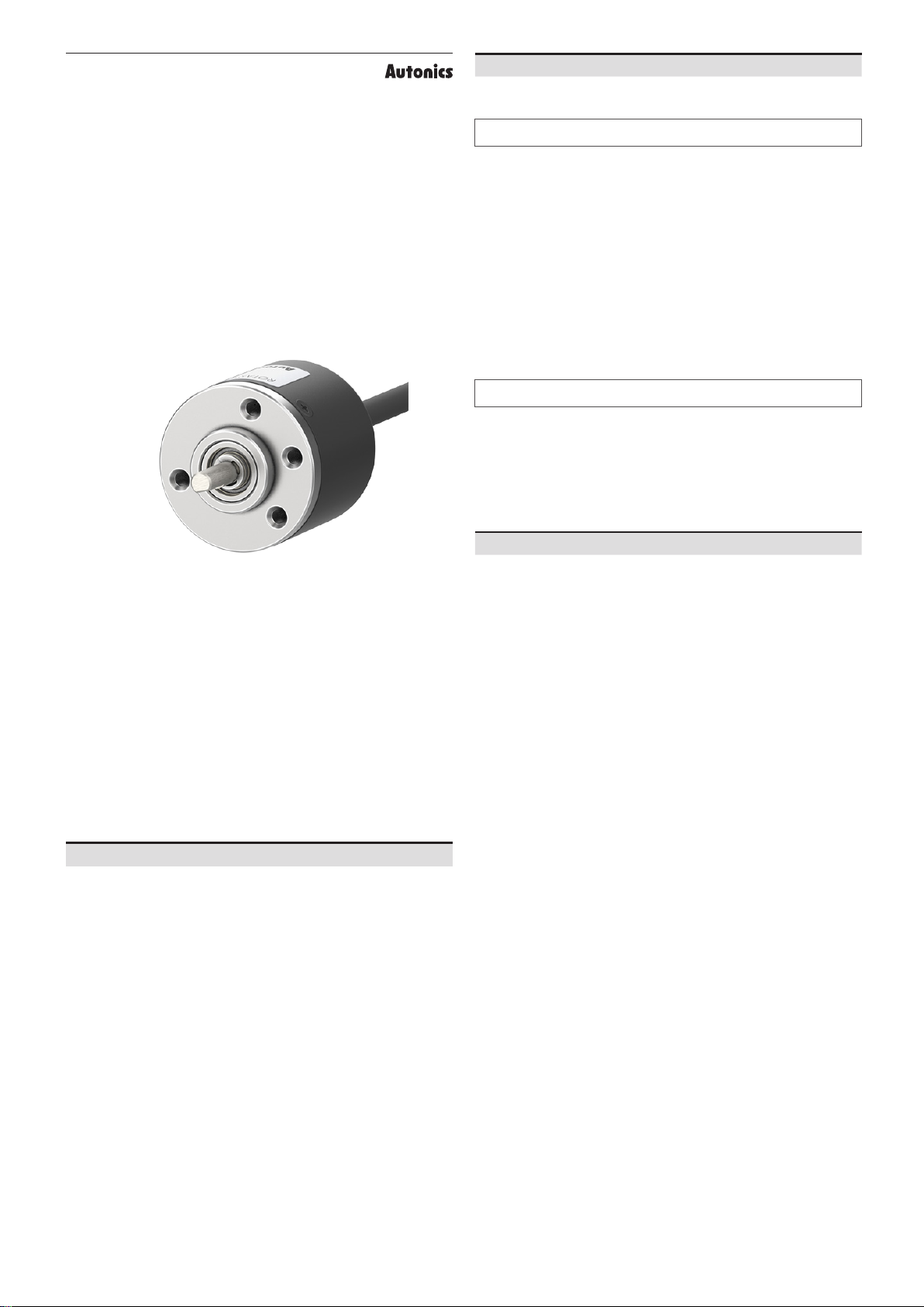
manuals.online logo
Brands
  1. Home
  2. •
  3. Brands
  4. •
  5. Autonics
  6. •
  7. Media Converter
  8. •
  9. Autonics E30 Series User manual

Autonics E30 Series User manual

This manual suits for next models

4

Other Autonics Media Converter manuals

Autonics SCM Series User manual

Autonics

Autonics SCM Series User manual

Autonics E80 Series User manual

Autonics

Autonics E80 Series User manual

Autonics BD-C Series User manual

Autonics

Autonics BD-C Series User manual

Autonics ENA Series User manual

Autonics

Autonics ENA Series User manual

Autonics E58 Series User manual

Autonics

Autonics E58 Series User manual

Autonics E60 Series User manual

Autonics

Autonics E60 Series User manual

Autonics E100 Series User manual

Autonics

Autonics E100 Series User manual

Autonics E58 Series User manual

Autonics

Autonics E58 Series User manual

Autonics E50 Series User manual

Autonics

Autonics E50 Series User manual

Autonics E58-A Series User manual

Autonics

Autonics E58-A Series User manual

Autonics EP50 Series User manual

Autonics

Autonics EP50 Series User manual

Autonics SCM Series User manual

Autonics

Autonics SCM Series User manual

Autonics SCM-WF48 User manual

Autonics

Autonics SCM-WF48 User manual

Autonics BFC Series User manual

Autonics

Autonics BFC Series User manual

Autonics CN-6000 Series User manual

Autonics

Autonics CN-6000 Series User manual

Autonics ENC Series User manual

Autonics

Autonics ENC Series User manual

Autonics SCM-US48I User manual

Autonics

Autonics SCM-US48I User manual

Autonics SCM-WF48 User manual

Autonics

Autonics SCM-WF48 User manual

Autonics E40 Series User manual

Autonics

Autonics E40 Series User manual

Autonics E40 Series User manual

Autonics

Autonics E40 Series User manual

Autonics E18 Series User manual

Autonics

Autonics E18 Series User manual

Autonics EPM50 Series User manual

Autonics

Autonics EPM50 Series User manual

Autonics E20 Series User manual

Autonics

Autonics E20 Series User manual

Popular Media Converter manuals by other brands

SoundTraxx Blunami BLU-2200 user guide

SoundTraxx

SoundTraxx Blunami BLU-2200 user guide

SPROLINK VA1 user manual

SPROLINK

SPROLINK VA1 user manual

Acclaim Lighting DDC-1-AC user guide

Acclaim Lighting

Acclaim Lighting DDC-1-AC user guide

Nikon AF-S TC-20E III user manual

Nikon

Nikon AF-S TC-20E III user manual

Axis AXIS Q7406 user manual

Axis

Axis AXIS Q7406 user manual

Omega TAC80B-J instruction sheet

Omega

Omega TAC80B-J instruction sheet

Zoom Thunderbolt TAC-2R Operation manual

Zoom

Zoom Thunderbolt TAC-2R Operation manual

OST iConverter 10/100M quick start guide

OST

OST iConverter 10/100M quick start guide

Vertiv Netsure user manual

Vertiv

Vertiv Netsure user manual

birddog MINI user guide

birddog

birddog MINI user guide

Roland GI-10 owner's manual

Roland

Roland GI-10 owner's manual

Wallenstein WX310 Operator's manual

Wallenstein

Wallenstein WX310 Operator's manual

Pace MSS 200-1 Service manual

Pace

Pace MSS 200-1 Service manual

Solar Converters EQ 12/24-50 manual

Solar Converters

Solar Converters EQ 12/24-50 manual

CYP EL-7400V Operation manual

CYP

CYP EL-7400V Operation manual

TIE MIDI 1i1o user manual

TIE

TIE MIDI 1i1o user manual

DCS Vivaldi Upsampler user manual

DCS

DCS Vivaldi Upsampler user manual

Westermo MCW-211 SERIES user guide

Westermo

Westermo MCW-211 SERIES user guide

manuals.online logo
manuals.online logoBrands
  • About & Mission
  • Contact us
  • Privacy Policy
  • Terms and Conditions

Copyright 2025 Manuals.Online. All Rights Reserved.

-|Transparent Guide|-
TCD210018AB
30 mm Diameter
Incremental Rotary Encoders
E30 Series
PRODUCT MANUAL
For your safety, read and follow the considerations written in the instruction
manual, other manuals and Autonics website.
󹃗


Features
󹮳 󹮳󹮳󹮳󹮳󹮹󹮳󹮳󹮳󹮳󹮳
󹮳 󹮳󹮳󹮳󹮳󹮳󹮳
󹮳 󹮳󹮳󹮳󹮳
󹮳 󹮳󹮽󹮳󹮳󹮳󹮳󹮳󹮳
󹮳 󹮳󹮳󹮳
󹮳 󹮳󹮽󹮳󹮳󹮳󹮳󹮹󹮳󹮳󹮺󹮳󹮳󹮳󹮳
Safety Considerations
• 
• 
᜸ Warning 
01. Fail-safe device must be installed when using the unit with machinery that
may cause serious injury or substantial economic loss. (e.g. nuclear power
control, medical equipment, ships, vehicles, railways, aircraft, combustion
apparatus, safety equipment, crime / disaster prevention devices, etc.)
󹃗
02. Do not use the unit in the place where 󹃙ammable / explosive / corrosive gas,
high humidity, direct sunlight, radiant heat, vibration, impact or salinity
may be present.
󹃗
03. Install on a device panel to use.
󹃗
04. Do not connect, repair, or inspect the unit while connected to a power
source.
󹃗
05. Check ‘Connections’ before wiring.
󹃗
06. Do not disassemble or modify the unit.
󹃗
᜸ Caution 
01. Use the unit within the rated speci󹃘cations.
󹃗
02. Do not short the load.
󹃗
03. Do not use the unit near the place where there is the equipment which
generates strong magnetic force or high frequency noise and strong
alkaline, strong acidic exists.

Cautions during Use
• 

• 

• 

• 
• 

• 

• 

• 


• 
󹃗



-|Transparent Guide|-
Product Components
• 
• 
• 
• 
Inner Circuit
• 
■Totem pole output ■NPN open collector output
LOAD
LOAD
CIRCUIT


NPN


CIRCUIT
LOAD
■Voltage output ■Line driver output

CIRCUIT
LOAD
CIRCUIT
A
A
Connections
• 
• 
• 
■ Totem pole / NPN open collector / Voltage output
Pin Color Function Pin Color Function
1 OUT A  +V
2White OUT B  
3 OUT Z 6 
 M17 6-pin layout
2

3 6
1

2

3 6
1

■Line driver output
Pin Color Function Pin Color Function
1 OUT A White OUT B
2Red OUT A 6  OUT B
3 +V 7 OUT Z
  8 OUT Z

9 
 M17 9-pin layout
12
3
7 8 9
  6
12
3
7 8 9
  6
Sold Separately
• 
Cautions during Installation
• 
󹃗
• 
• 

• 󹃗
• 


• 
Ordering Information

󹃗
E30 ❶ ❷ -❸-❹-❺-❻-❼
❶ Shaft type

❺ Control output




❷ Shaft outer diameter
󹮽󹮳󹮳󹮳
❸ Resolution

󹃗
❻ Power supply


❹ Output phase

ABZ
❼ Connection


Output Waveform
• 

• 󹃖T
T
8
■ Totem pole /
NPN open collector /
Voltage output
■Line driver output
 T
2
H
L
T
A
H
L
Z

H
L
B
T
T
8
T
2T

H
L
H
L
H
L
H
L
H
L
H
L
T
A
B
Z
A
B
Z

T
2T

T
T
8
 T
2
Model E30S4-□-
3-T-□-□
E30S4-□-
3-N-□-□
E30S4-□-
3-V-□-□
E30S4-□-
6-L-5-□
Power supply 



Current
consumption  

Insulation
resistance 
Dielectric strength 
Vibration 

Shock 
Ambient temp. 
Ambient humi. 
Protection rating 
Connection 
Cable spec. 

Wire spec. 
Connector spec.  
type
Speci󹃘cations
Model E30S4-□-
3-T-□-□
E30S4-□-
3-N-□-□
E30S4-□-
3-V-□-□
E30S4-□-
6-L-5-□
Resolution 
Control output Totem pole

NPN open
  Line driver

    ABZ
󹃘   
    
󹃘    



 



 
Response speed
01)

 
Max. response freq.

Max. allowable
revolution 04) 
Starting torque 
Inertia moment 22
Allowable shaft load

Unit weight 
Approval    

󹮳
resistance


 × 60 sec]
-|
Transparent Guide|-
Dimensions
•
•
3
6
0
0
■Coupling
21
•
•
•
Appearance Power
supply Connector 1Connector 2 Length Model
DC
Sold Separately: M17 Connector Cable
•
Appearance Power
supply Connector 1Connector 2 Length Model
DC