Autoscript Control Net HC-1 User manual

MFC-D
Control Net
Controllers and Smart Combiner
Control Net
Controllers and Smart Combiner
Part Nos. HC-1
www.autoscript.tv
EN
MFC
SCB

Copyright © 2014
All rights reserved.
Original Instructions: English
All rights reserved throughout the world. No part of this document may be stored in a retrieval system,
transmitted, copied or reproduced in any way, including, but not limited to, photocopy, photograph,
magnetic or other record without the prior agreement and permission in writing of the Vitec Group plc.
Disclaimer
The information contained in this manual is believed to be correct at the time of printing. Vitec Videocom
Ltd reserves the right to make changes to the information or specifications without obligation to notify any
person of such revision or changes. Changes will be incorporated in new versions of the publication.
We are making every effort to ensure that our manuals are updated on a regular basis to reflect changes
to product specifications and features. Should this manual not contain information on the core functionality
of your product, please let us know. You may be able to access the latest revision of this manual from our
website.
Vitec Videocom Ltd reserves the right to make changes to product design and functionality without
notification.
Trademarks
All product trademarks and registered trademarks are the property of The Vitec Group Plc.
All other trademarks and registered trademarks are the property of their respective companies.
Published by:
Vitec Videocom Ltd
Supports Technical Publications Department
Western Way, Bury St Edmunds
Suffolk IP33 3TB
United Kingdom
Email: [email protected]

1
Contents
Safety. . . . . . . . . . . . . . . . . . . . . . . . . . . . . . . . . . . . . . . . . . . . . . . . . 2
About this Guide . . . . . . . . . . . . . . . . . . . . . . . . . . . . . . . . . . . . . . . 3
Components and Connections . . . . . . . . . . . . . . . . . . . . . . . . . . . . 4
Key Components . . . . . . . . . . . . . . . . . . . . . . . . . . . . . . . . . . . . 4
Box Contents . . . . . . . . . . . . . . . . . . . . . . . . . . . . . . . . . . . . . . . 8
Tools Required . . . . . . . . . . . . . . . . . . . . . . . . . . . . . . . . . . . . . . 9
Installation . . . . . . . . . . . . . . . . . . . . . . . . . . . . . . . . . . . . . . . . . . . 10
Controller Connection Options . . . . . . . . . . . . . . . . . . . . . . . . . 10
Control Net Connections. . . . . . . . . . . . . . . . . . . . . . . . . . . . . . 10
Serial Connections . . . . . . . . . . . . . . . . . . . . . . . . . . . . . . . . . . 11
Power Connections. . . . . . . . . . . . . . . . . . . . . . . . . . . . . . . . . . 13
System Connections - Single Controllers . . . . . . . . . . . . . . . . . 14
System Connections - One Smart Combiner Box . . . . . . . . . . 15
System Connections - Two Smart Combiner Boxes . . . . . . . . . 16
Adding Additional Smart Combiner Boxes . . . . . . . . . . . . . . . . 17
Powering Up . . . . . . . . . . . . . . . . . . . . . . . . . . . . . . . . . . . . . . . 17
Operation . . . . . . . . . . . . . . . . . . . . . . . . . . . . . . . . . . . . . . . . . . . . 18
Using the Hand Controller . . . . . . . . . . . . . . . . . . . . . . . . . . . . 18
Using the Foot Controller . . . . . . . . . . . . . . . . . . . . . . . . . . . . . 20
Using the Desk Controller. . . . . . . . . . . . . . . . . . . . . . . . . . . . . 21
Priority Control . . . . . . . . . . . . . . . . . . . . . . . . . . . . . . . . . . . . . 22
Maintenance . . . . . . . . . . . . . . . . . . . . . . . . . . . . . . . . . . . . . . . . . . 23
Routine Maintenance . . . . . . . . . . . . . . . . . . . . . . . . . . . . . . . . 23
Cleaning . . . . . . . . . . . . . . . . . . . . . . . . . . . . . . . . . . . . . . . . . . 23
Changing the Fuse (Smart Combiner Box). . . . . . . . . . . . . . . . 23
Troubleshooting. . . . . . . . . . . . . . . . . . . . . . . . . . . . . . . . . . . . . . . 24
Technical Specification . . . . . . . . . . . . . . . . . . . . . . . . . . . . . . . . . 25
General Notices . . . . . . . . . . . . . . . . . . . . . . . . . . . . . . . . . . . . . . . 26

2
Safety
Important information on the safe installation and operation of
this product. Read this information before operating the product.
For your personal safety, read these instructions. Do not operate
the product if you do not understand how to use it safely. Save
these instructions for future reference.
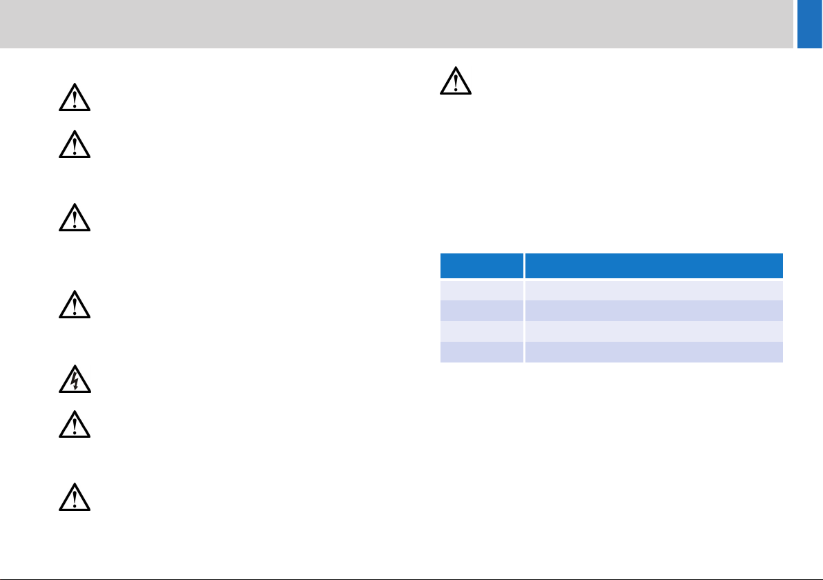
Warning Symbols Used in these Instructions
Safety cautions are included in these instructions. These safety
instructions must be followed to avoid possible personal injury and
avoid possible damage to the product.
Intended Use
The Control Net controllers and Smart Combiner Box have been
designed to provide prompter text control as part of a high quality
teleprompting facility for television broadcasting.
They are intended for use by television presenters and camera
operators, installed within a TV studio environment, or on outside
broadcasts (OB) when protected from weather by a suitable waterproof
cover.
Electrical Connection
Basic Electrical Insulation (Class 1 equipment)
Mounting and Installation
WARNING!
Where there is a risk of personal injury or injury to others,
comments appear supported by the warning triangle symbol.
Where there is a risk of damage to the product, associated
equipment, process or surroundings, comments appear
supported by the word ‘Caution’.
ELECTRIC SHOCK
Where there is a risk of electric shock, comments appear
supported by the hazardous voltage warning triangle.
WARNING! Risk of electric shock. Always check cables for
signs of damage. Damaged cables can cause personal injury
and/or damage the equipment.
CAUTION! The products must be connected to a power
supply of the same voltage (V) and current (A) as indicated
on the products. Refer to the technical specifications for the
products.
CAUTION! Only use the power cable specified for the
products and certified for the country of use.
CAUTION! Using alternative power sources will invalidate
the system EMC liability.
WARNING! This product is Class 1 equipment. For safe
operation this equipment must be connected to a power
supply that has a protective earth connection (US: ground).
WARNING! Always ensure that all power and auxiliary
communications cables are routed so that they do not
present any danger to personnel. Take care when routing
cables in areas where robotic equipment is in use.

3
Safety and About this Guide
Water, Moisture and Dust
Ventilation
Operating Environment
Cleaning
Maintenance
About this Guide
This guide describes the installation and operation of the Control Net
controllers and Smart Combiner Box, as part of a full prompting system,
using the range of compatible equipment and connecting cables
available for various configurations.
The range of products covered in this guide consists of the following:
WARNING! Protect the product from water, moisture and
dust. The presence of electricity near water can be
dangerous.
WARNING! When using this product outside, protect from
rain using a suitable waterproof cover.
WARNING! Slots and openings are intended for ventilation
purposes to ensure reliable operation of the product, and
protect it from overheating. Do not block or cover any slots
and openings.
CAUTION! The product should not be used outside the
operating temperature limits. Refer to the product technical
specifications for the operating limits for the product.
WARNING! Risk of electric shock. Always disconnect and
isolate the product from the power supply before cleaning.
CAUTION! Do not use solvent or oil-based cleaners,
abrasives or wire brushes.
WARNING! Servicing or repair of this product must only be
performed by qualified and trained electrical engineers.
WARNING! The fitting of non-approved parts and
accessories, or the carrying out of non-approved alterations
or servicing can be dangerous and could affect the safety of
the product. It may also invalidate the terms and conditions
of the product warranty.
Part No. Description
HC-1 Optical five button hand control
MFC Magnetic foot control
MFC-D Remote six button desk pad
SCB Smart combiner box

4
Components and Connections
Key Components
Hand Controller - Front View Hand Controller - Rear View
1‘Next story’ button
2‘Previous story’ button
3‘Back to top of script’ button
4Programmable function button 1
5‘Blank screen’ / programmable function button 2
6Scroll control dial
1
3
2
4
5
6
7Scroll control indication LED
8DC power socket
9Serial control socket
10 Control Net socket
7
9
8
10

5
Components and Connections
Foot Controller- Front View Foot Controller - Rear View
1Forward scroll control foot pedal
2Direction indicator LED
3Cable guard
4Reverse scroll control button
1
3
2
4
5DC power socket
6Control Net connector
7Serial connector for MFC-D (RJ11)
8Serial connector (9 way D type)
5
6
7
8
Cable guard removed
for illustrative purposes

6
Components and Connections
Desk Controller- Front View Desk Controller - Bottom View
1‘Next story’ button
2‘Previous story’ button
3‘Back to top of script’ button
4Toggle reverse button
5Scroll direction indicator LED
6Function button 1
7Function button 2
1
3
2
456
7
8Serial connector (RJ11)
9Cable strain relief clamp
8
9

7
Components and Connections
Smart Combiner Box
1Power indicator LED 5Serial connector (9 way D type)
2AC power inlet socket 6Control Net input or expansion loop output
3Fuse holder 7Control Net inputs
4Power switch
5
6
1
2
3
4
7

8
Components and Connections
Box Contents
Hand Controller
Smart Combiner
Foot Controller Package - MFC-PKG1
No. Part Description
1 HC-1 Five button optical hand control
No. Part Description
1 SCB Smart combiner box
1
1
No. Part Description
1 MFC Magnetic foot control
2 MFC-D Desk controller
3 PSU-HR Hirose power supply
4 RJ11-2 RJ11 connecting cable, 2 metres
5 RJ11-5 RJ11 connecting cable, 5metres
1
3
5
2
4

9
Components and Connections
Tools Required
Pozidriv® PZ-1 screwdriver.

10
Installation
Controller Connection Options
Special consideration should be given when choosing locations and
connection methods to install and use the controllers and smart
combiner box.
• Using Control Net connections, the cables can be up to 300
metres in length.
• Serial connections are used for short connection distances, with a
maximum cable length of 18 metres.
Control Net Connections
Hand Controller
Foot Controller
Control Net
300 m (984 ft)
Serial
18 m (59 ft)
Control Net connections should always be made with
screened 75Ω coaxial cable.The cable screen must be
connected to earth (ground) at both ends.

11
Installation
Smart Combiner Box
The smart combiner box has six Control Net inputs available. One of
the inputs can also be used as an output to either link back to the
control system, or loop through to another combiner.
Serial Connections
Single controllers can also be connected using a serial connection. The
serial connection can also provide power to the connected controller.
Serial connections are restricted to a maximum length of 18 metres (59
feet).
Hand Controller
Foot Controller
Inputs x6
Output x1

12
Installation
Desk Controller
The desk controller is connected with a short local serial link to the foot
controller using an RJ11 connecting cable.
Strain Relief Clamp
The desk controller is fitted with a strain relief clamp which must be
used to prevent the cable from becoming disconnected during use.
RJ11 cable

13
Installation
Smart Combiner Box
The smart combiner box has a serial out connector. This can be used
to connect it directly to the control system.
Power Connections
Hand Controller
Foot Controller
Desk Controller
The desk controller receives DC
power via the RJ11 serial
connection, and does not require
a separate connection.
Smart Combiner Box
12VDC
12VDC
100-240VAC

14
Installation
System Connections - Single Controllers
XBox and WinPlus Host PC
Foot Controller
Hand Controller
Control Net connections
(75 BNC coax cables)Ω
Serial connections (9-pin D
connecting cable)
Key
Desk Controller
Serial connections (RJ11
connecting cable)
Power Supply
PSU-HR is required for a
controller not connected
using a serial link

15
Installation
System Connections - One Smart Combiner Box
Six Control Net inputs available
on the smart combiner (five if
the Control Net output is used
for connection to the XBox)
Smart
Combiner Box
XBox and WinPlus Host PC
Hand Controllers
Foot and Desk Controllers
The diagram shows an example of an installation using one smart combiner box.
Any combination of controllers (hand or foot and desk) can be used.
Power Supply Individual PSU-HRs
are required for
controllers not
connected using a
serial link

16
Installation
System Connections - Two Smart Combiner Boxes
Five controllers (mixed)
connected to the first
smart combiner
Smart
Combiner Box(1)
Smart
Combiner Box(2)
Additional five controllers
(mixed) connected to the
second smart combiner
Control Net loop
out to second
smart combiner
XBox and WinPlus Host PC
Power Supply Individual PSU-HRs
are required for all
the controllers.

17
Installation
Adding Additional Smart Combiner Boxes
Additional hand, foot and desk controllers can be added into a system
by looping more smart combiner boxes onto the Control Net.
Powering Up
The hand, foot and desk controllers are automatically powered up when
DC power is connected.
Smart combiner box
To power up the smart combiner box, operate the power switch on the
rear of the product.
When three or more smart combiners are connected in
one installation, response time delays may be incurred
when operating the controllers.
Control Net
loop in from
previous smart
combiner box
Control Net loop
out to next smart
combiner box
Four Control Net
inputs available
for additonal
controllers

18
Operation
Using the Hand Controller
The hand controller is typically located in the control room and operated
in close conjunction with the WinPlus software. The scroll speed and
direction of the prompted text is controlled using a rotary dial. Push
buttons are provided for next and previous pages/stories selection and
other functions described in this section.
Scroll Control
Story Control Buttons
Forward
scroll control
Stop scroll
(indent)
Reverse
scroll control
Advances the prompter text forward by one page/
story for each press.
First press - Back to top of the current page/story
Subsequent presses - Back by page/story.
Pressed together - Returns the prompter text to the
overall top of the script.
Returns the prompter text to the beginning of the
script.
This manual suits for next models
3
Table of contents
Other Autoscript Professional Video Accessories manuals

Autoscript
Autoscript X-Box Ultra WP-NXU User manual

Autoscript
Autoscript XBox-IP User manual

Autoscript
Autoscript ELP 15 PLUS User manual

Autoscript
Autoscript LED8TFT-ME User manual

Autoscript
Autoscript EPIC-IP User manual

Autoscript
Autoscript XBOXLITE User manual

Autoscript
Autoscript LED12TFT-ME User manual

Autoscript
Autoscript FC-IP User manual