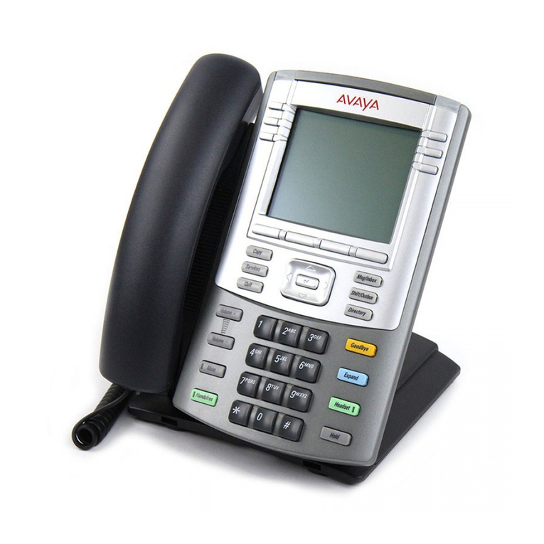
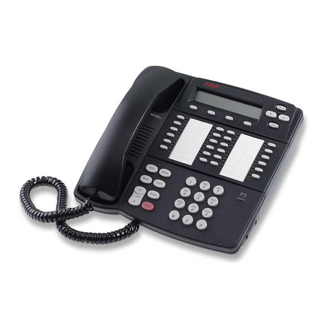
Avaya 3606 Operator's manual

Avaya™ 3606 Wireless IP Telephone
Installation and Configuration Guide
555-301-101
Issue 1
Part Number 72-0278-02
Revision A
February 2003

2003, Avaya Inc.
All Rights Reserved, Printed in U.S.A.
Notice
Every effort was made to ensure that the information in this book was complete and accurate at the time of printing. However, information is subject to
change.
Avaya Web Page
The world wide web home page for Avaya is: http://www.avaya.com
Preventing Toll Fraud
Toll Fraud is the unauthorized use of your telecommunications system by an unauthorized party (for example, a person who is not a corporate employee,
agent, subcontractor, or working on your company’s behalf). Be aware that there is a risk of toll fraud associated with your system and that, if toll fraud
occurs, it can result in substantial additional charges for your telecommunications services.
Avaya Fraud Intervention
If you suspect that you are being victimized by toll fraud and you need technical assistance or support, call the Technical Service Center’s Toll Fraud
Intervention Hotline at 1.800.643.2353.
Providing Telecommunications Security
Telecommunications security of voice, data, and/or video communications is the prevention of any type of intrusion to, that is, either unauthorized or
malicious access to or use of, your company’s telecommunications equipment by some party.
Your company’s “telecommunications equipment” includes both this Avaya product and any other voice/data/video equipment that could be accessed via
this Avaya product (that is, “networked equipment”).
An “outside party” is anyone who is not a corporate employee, agent, subcontractor, or a person working on your company’s behalf. Whereas, a
“malicious party” is Anyone, including someone who may be otherwise authorized, who accesses your telecommunications equipment with either
malicious or mischievous intent.
Such intrusions may be either to/through synchronous (time-multiplexed and/or circuit-based) or asynchronous (character-, message-, or packet-based)
equipment or interfaces for reasons of:
• Utilization (of capabilities special to the accessed equipment)
• Theft (such as, of intellectual property, financial assets, or toll-facility access)
• Eavesdropping (privacy invasions to humans)
• Mischief (troubling, but apparently innocuous, tampering)
• Harm (such as harmful tampering, data loss or alteration, regardless of motive or intent)
Be aware that there could be a risk of unauthorized intrusions associated with your system and/or its networked equipment. Also realize that, if such an
intrusion should occur, it could result in a variety of losses to your company, including but not limited to, human/data privacy, intellectual property,
material assets, financial resources, labor costs, and/or legal costs).
Your Responsibility for Your Company’s Telecommunications Security
The final responsibility for securing both this system and its networked equipment rests with you – an Avaya customer’s system administrator, your
telecommunications peers, and your managers. Base the fulfillment of your responsibility on acquired knowledge and resources from a variety of sources
including but not limited to:
• Installation documents
• System administration documents
• Security documents
• Hardware-/software-based security tools
• Shared information between you and your peers
• Telecommunications security experts
To prevent intrusions to your telecommunications equipment, you and your peers should carefully program and configure your:
• Avaya provided telecommunications systems and their interfaces
• Avaya provided software applications, as well as their underlying hardware/ software platforms and interfaces
• Any other equipment networked to your Avaya products
Federal Communications Commission Statement
Part 15: Class A Statement. This equipment has been tested and found to comply with the limits for a Class A digital device, pursuant to Part 15 of the
FCC Rules. These limits are designed to provide reasonable protection against harmful interference when the equipment is operated in a commercial
environment. This equipment generates, uses, and can radiate radio-frequency energy and, if not installed and used in accordance with the instructions,
could cause harmful interference to radio communications. Operation of this equipment in a residential area is likely to cause harmful interference, in
which case the user will be required to correct the interference at his own expense.
Industry Canada (IC) Interference Information
This digital apparatus does not exceed the Class A limits for radio noise emissions set out in the radio interference regulations of Industry Canada.
Le Présent Appareil Nomérique n’émet pas de bruits radioélectriques dépassant les limites applicables aux appareils numériques de la class A préscrites
dans le reglement sur le brouillage radioélectrique édicté par le Industrie Canada.
European Union Declaration of Conformity
The “CE” mark affixed to the equipment means that it conforms to the referenced European Union (EU) Directives listed below:
EMC Directive 89/336/EEC
Low-Voltage Directive 73/23/EEC
For more information on standards compliance, contact your local distributor.
3606 Wireless IP Telephone
Installation and Configuration Guide
Table of Contents
1. About This Document.................................................................................................... 5
1.1 Contacting Avaya 5
1.2 Icons and Conventions 5
2. 3606 Wireless IP Telephone Overview.......................................................................... 6
2.1 Quick Start Guide 6
2.2 System Diagram 7
2.3 System Components 7
3. The 3606 Wireless IP Telephone................................................................................... 9
3.1 Specifications 9
3.2 The Display 9
4. Avaya Call Server Configuration................................................................................. 11
4.1 Configuring a Standalone Station 11
4.2 Configuring an Associated Station 11
5. 3606 Wireless IP Telephone Configuration................................................................ 12
5.1 Opening and Using the Admin Menu 12
5.2 User-defined Preferences 18
6. License Management................................................................................................... 20
6.1 Requirements 20
6.2 Configuration Process 20
7. Avaya Call Server Integration Factors........................................................................ 22
8. Feature Programming.................................................................................................. 24
9. Testing a Wireless Telephone..................................................................................... 25
555-301-101, Issue 2 3
February 2003

3606 Wireless IP Telephone
Installation and Configuration Guide
10. Certifying the 3606 Wireless IP Telephones........................................................... 26
10.1 Site Certification 26
10.2 Site Survey Mode 26
10.3 Solving Coverage Issues 27
11. Software Maintenance.............................................................................................. 28
11.1 Upgrading Wireless Telephones 28
12. Troubleshooting Wireless Telephone Problems.................................................... 30
12.1 Access Point Problems 30
12.2 Configuration Problems 30
12.3 Wireless Telephone Status Messages 31
4 555-301-101, Issue 2
February 2003

3606 Wireless IP Telephone
Installation and Configuration Guide
1. About This Document
This document explains how to configure and maintain the 3606 Wireless IP Telephone with an Avaya
Call Server (such as an Avaya™MultiVantage™on a DEFINITY®Server SI or an Avaya™S8100
Media Server with CMC1 Media Gateway).
1.1 Contacting Avaya
To access software updates, the most current troubleshooting information, and other important
information about the 3606 Wireless IP Telephone, go to http://avaya.com/support. If you have
questions about or problems with the 3606 Wireless IP Telephone that you cannot resolve after reading
this document, contact Avaya Technical Support at 1 800 242-2121 (USA only) or your local
authorized Avaya dealer.
1.2 Icons and Conventions
This manual uses the following icons and conventions.
Caution! Follow these instructions carefully to avoid danger.
!Note these instructions carefully.
NORM This typeface indicates a key, label, or button on Avaya hardware.
555-301-101, Issue 2 5
February 2003

3606 Wireless IP Telephone
Installation and Configuration Guide
2. 3606 Wireless IP Telephone Overview
The 3606 Wireless Telephone is a mobile handset for workplace IP telephone systems. The Wireless
Telephone operates over an 802.11b wireless Ethernet LAN providing users a wireless voice over IP
(VoIP) extension. By seamlessly integrating with an Avaya Call Server (such as an Avaya™
MultiVantage™on a DEFINITY®Server SI and an Avaya™S8100 Media Server with CMC1 Media
Gateway), Wireless Telephone users are provided with high-quality mobile voice communications
throughout the workplace. The Wireless Telephone gives users the freedom to roam throughout the
workplace while providing all the features and functionality of an IP desk phone.
The 3606 Wireless IP Telephone provides a wireless extension to the Avaya Call Server. The Wireless
Telephones reside on the wireless LAN with other wireless devices using Direct Sequence Spread
Spectrum (DSSS) radio technology. The handset radio transmits and receives packets at up to 11Mb/s.
A Wireless Telephone must be administered on the Avaya Call Server for the specific features and
lines to be accessed by the Wireless Telephone. After the handset is registered, it receives its
configuration information from the Avaya Call Server.
The 3606 Wireless IP Telephone supports Wired Equivalent Privacy (WEP) as defined by the 802.11
specification. Avaya offers the product with both 40-bit and 128-bit encryption. WEP increases the
security of the wireless LAN to a level similar to a wired Ethernet LAN.
2.1 Quick Start Guide
1. A wireless LAN must be properly configured and operational through the use of 802.11b wireless
access points (APs).
2. A TFTP Server must be available on the network in order to load the appropriate software into the
Wireless Telephones. See Section 6 “License Management” for detailed instructions for loading
software on Wireless Telephones.
3. The Avaya Call Server must be connected to your network and completely operational.
4. The Avaya Voice Priority Processor, which controls the QoS on the wireless LAN for the Wireless
Telephones, must be on the same subnet as the Wireless Telephones and have the proper versions
of software. Visit http://avaya.com/support to download the latest Avaya Voice Priority Processor
software.
5. Add a station on the Avaya Call Server for each Wireless Telephone. You will administer each
Wireless Telephone as an Avaya 4606 IP Telephone.
6. Configure your Wireless Telephone to ensure that it is associated with the Wireless LAN, has the
appropriate software and is registered to the Avaya Call Server. See “License Management” for
detailed instructions for loading software onto Wireless Telephones.
6 555-301-101, Issue 2
February 2003

3606 Wireless IP Telephone
Installation and Configuration Guide
2.2 System Diagram
The following diagram shows the components residing on a network with the Avaya Call Server,
access points (APs), and wireless LAN Ethernet Switched Hub:
access
p
oint
Ethernet cable
Phone cable
PSTN
or
PBX
Avaya Call Server
Avaya IP
Phones
access
p
oint
Wireless
Telephones
Wireless
POS
Ethernet switch
Avaya Voice Priority
Processor
2.3 System Components
• 3606 Wireless IP Telephone – The 3606 Wireless IP Telephone is a lightweight, durable handset
specifically designed for mobile workplace use within a facility using the Avaya Call Server and
802.11 APs in a wireless LAN.
Wireless Telephone functionality is provided by emulating the Avaya 4606 desk set. The Wireless
Telephone supports four predefined feature keys and a mixture of six programmable line and
feature keys. Among other features, the Wireless Telephone can receive calls directly, receive
transferred calls, transfer calls to other extensions, make conference calls, and make outside and
long distance calls (subject to the restrictions applied in your facility.) The Wireless Telephones are
to be used on-premises; they are not cellular or satellite phones.
3606 Wireless IP Telephones use direct sequence spread spectrum radio technology (DS) to
transmit audio packets over wireless LAN APs that support the Avaya Wireless PC card.
555-301-101, Issue 2 7
February 2003

3606 Wireless IP Telephone
Installation and Configuration Guide
• Avaya Voice Priority Processor – SpectraLink Voice Priority (SVP) is the Quality of Service
(QoS) mechanism that is implemented in the Wireless Telephone and AP to enhance voice quality
over the wireless network. SVP gives preference to voice packets over data packets on the wireless
medium, increasing the probability that all voice packets are transmitted efficiently and with
minimum or no delay. SVP is fully compliant with the IEEE 802.11 and 802.11b standards.
The Avaya Voice Priority Processor is an Ethernet LAN appliance that works with the AP to
provide QoS on the wireless LAN. All packets to and from the 3606 Wireless IP Telephones pass
through the Avaya Voice Priority Processor and are encapsulated for prioritization as they are
routed to and from the Avaya Call Server.
SVP is required for QoS because the current IEEE 802.11b wireless LAN standard provides no
mechanism for differentiating audio packets from data packets. This standard is undergoing
revision to version 802.11e to provide all the functionality of SVP in an industry standard thus
ensuring high-quality voice in a mixed client environment. Once 802.11e is ratified, Avaya and its
802.11 technology partners will adopt the new specification. When the 802.11e specification
replaces SVP, the Wireless Telephones can be upgraded and the Avaya Voice Priority Processor
can be removed from the system.
• Avaya Call Server – the call-processing component of the Avaya IP telephony solution.
• Access Points – provide the connection between the wired Ethernet LAN and the wireless
(802.11) LAN. Access points must be positioned in all areas where Wireless Telephones will be
used. The number and placement of access points will affect the coverage area and capacity of the
wireless system. Typically, the requirements for use of 3606 Wireless IP Telephones are similar to
that of wireless data devices.
• Ethernet Switch – interconnects multiple network devices, including the Avaya Voice Priority
Processor, Avaya Call Server, Avaya IP Phones and the access points. Ethernet switches provide
the highest performance networks, which can handle combined voice and data traffic, and are
required when using the 3606 Wireless IP Telephones.
Although a single Ethernet switch network is recommended, the Wireless Telephones and the
Avaya Voice Priority Processor can operate in larger, more complex networks, including networks
with multiple Ethernet switches, routers, VLANs and/or multiple subnets. However, in such
networks, it is possible for the Quality of Service (QoS) features of the Avaya Voice Priority
Processor to be compromised and voice quality may suffer. Any network that consists of more than
a single Ethernet switch should be thoroughly tested to ensure any quality issues are detected.
Note that the 3606 Wireless IP Telephones cannot “roam” from one subnet to another. If routers
and multiple subnets are in use, the Wireless Telephones must only use access points attached to a
single subnet, or be powered off and back on to switch to a different subnet.
• Avaya IP Phone – The wired-LAN desk sets provided by Avaya for use with the Avaya Call
Server.
• TFTP Server – Required in the system to distribute software to the Wireless Telephones.
8 555-301-101, Issue 2
February 2003

3606 Wireless IP Telephone
Installation and Configuration Guide
3. The 3606 Wireless IP Telephone
3.1 Specifications
Radio frequency 2.4000 – 2.4835 GHz
Transmission type Direct Sequence Spread Spectrum (DSSS)
Transmit data rate up to 11 Mb/s
Radio QoS SpectraLink Voice Priority (SVP)
Wireless security Wired Equivalent Privacy (WEP), 40bit and 128bit
FCC certification Part 15.247
Management DHCP, TFTP
Voice encoding G.711
VoIP Protocols CCMS
Transmit power 100 mW peak, < 10 mW average
Display 2 x 16 character alphanumeric, plus line and status indicators
Dimensions 5.9 “ L x 2.0” W x 1.0 “ D
Weight 6.0 ounces, maximum
Battery capacity 2 hours talk time, 80 hours standby
3.2 The Display
Alphanumeric
The 3606 Wireless IP Telephone display has two lines capable of displaying 16 alphanumeric
characters each. Display information provided by the Avaya Call Server when the Wireless Telephone
is off-hook will be passed directly to the Wireless Telephone display. The Wireless Telephone will
emulate the 4606 display handling. Certain characters may be used by the Avaya Call Server that are
not implemented in the Wireless Telephone such as definable and special characters.
555-301-101, Issue 2 9
February 2003

3606 Wireless IP Telephone
Installation and Configuration Guide
MSG Icon
The message-waiting icon (MSG) is activated in a similar fashion as the message indicator of the
display set. The Message Waiting feature must be assigned to a button in order to support the
message-waiting icon.
Ringing and Tones
The ringing types (normal or vibrator) are programmed by the Wireless Telephone user into the
Wireless Telephone and are not accessible or changeable by the Avaya Call Server. Whenever
possible the audible and vibrating ringer on the Wireless Telephone will follow the command provided
by the Avaya Call Server.
Audio Features
The Avaya IP Phone Model 4606 speakerphone features will not be made available on the Wireless
Telephone.
Line Indicators
The line indicators on the Wireless Telephone will illuminate to mimic the LEDs next to Line keys on
the Avaya 4606. Note, however, that the Wireless Telephone will indicate line numbers based on the
order line assignments are received from the Avaya Call Server, regardless of which button the line is
assigned to during system administration.
10 555-301-101, Issue 2
February 2003

3606 Wireless IP Telephone
Installation and Configuration Guide
4. Avaya Call Server Configuration
You can configure the 3606 Wireless Telephone as a stand-alone station or associate it with a desk
station. When the 3606 Wireless Telephone is associated with a desk station, the user can make and
handle calls from either the 3606 Wireless Telephone or the desk station.
4.1 Configuring a Standalone Station
To configure a 3606 Wireless Telephone as a stand-alone station, you must add a station on the Avaya
Call Server for the 3606 Wireless Telephone.
To administer a stand-alone station on the Avaya Call Server for a Wireless Telephone:
1. From the Avaya Call Server administration software, add a new station.
2. Set “Type” to “4606.”
3. Complete the remainder of the station form as you would for a desk station.
4. Repeat Steps 1 through 3 for each stand-alone Wireless Telephone.
4.2 Configuring an Associated Station
To configure a 3606 Wireless Telephone as an associated station, you must add a station on the Avaya
Call Server for the 3606 Wireless Telephone and then associate that station with a desk station.
To administer an associated station on the Avaya Call Server for a Wireless Telephone:
1. From the Avaya Call Server administration software, add a new station.
2. Set “Type” to “4606.”
3. Set “Security Code” to the same security code used for the extension to which this Wireless
Telephone will be associated (that is, the desk station). You can use a different security code,
but to make it easier for the user it is recommended that you use the same security code as the
desk station.
4. Set “Message Lamp Ext” to the extension of the associated desk station.
5. Set “Bridged Call Alerting” to “y.”
6. Set “Auto Select Any Idle Appearance” to “y.”
7. For Button Assignments, create bridged appearances to the line appearances on the desk
station.
8. Add additional feature buttons to buttons 4 and 5, if desired.
9. Repeat Steps 1 through 8 for each Wireless Telephone.
!When making changes to feature buttons, the phone must be power
cycled.
555-301-101, Issue 2 11
February 2003

3606 Wireless IP Telephone
Installation and Configuration Guide
5. 3606 Wireless IP Telephone Configuration
The Wireless Telephone can be automatically configured for IP address and/or ESSID by enabling
DHCP and/or ESSID Learning, respectively.
If any of the Wireless Telephone’s default settings need to be changed, the following procedure should
be followed.
5.1 Opening and Using the Admin Menu
The Admin menu contains configuration options that are stored locally (on each Wireless Telephone).
Every Wireless Telephone is independent and if the default settings are not desired, the admin options
must be set in each Wireless Telephone requiring different settings.
1. With the Wireless Telephone powered OFF, simultaneously press and hold the PWR and END
keys.
2. After hearing three beeps, release the PWR key, then release the END key. The first option on
the Admin menu displays.
!If an admin password has been set, the display will require its entry before
opening the Admin menu. If no password is set, the display will proceed
directly into the Admin menu.
3. Press the left or right arrow keys (# and *) on the Wireless Telephone to scroll through the
menu options.
4. Press
0(zero) to change the selected option.
5. Press
FCN to return to the previous menu level.
6. Press
END to exit the menus.
An asterisk (*) next to an option indicates that it is selected. The default settings are shown below with
an * prior to the option.
The following table lists the Admin menu items. Detailed descriptions of each item appear below the
table.
12 555-301-101, Issue 2
February 2003

3606 Wireless IP Telephone
Installation and Configuration Guide
Admin Menu Items 2nd Level 3rd Level
IP Address Use DHCP
Static IP
Phone IP
TFTP Server IP
OAI Server IP
Default Gateway
Subnet Mask
SVP Server IP
Static Entry
ESS ID Learn Once
Learn Always
License Management Set Current
Restore Defaults
Site Survey Mode
Regulatory Domain
Authentication
Open System
Shared Key
Encryption WEP On/Off
Key Information
Default Key
Key Length
Key #
Admin PW
Ext.
Password
Avaya Call Server IP
IP Address
There are two modes in which the Wireless Telephone can operate: DHCP enabled or Static IP. Select
the mode for operation from the IP Address menu:
* Use DHCP: will use Dynamic Host Configuration Protocol to assign an IP address each time
the Wireless Telephone is turned on. If DHCP is enabled, the Wireless Telephone also receives
all other IP address configuration from the DHCP server.
Static IP: allows you to manually set a fixed IP address. If selected, the Wireless Telephone
will prompt for the IP addresses of each configurable network component. When entering
addresses, enter the digits only, including leading zeroes. No periods are required.
Regardless of the mode in which the Wireless Telephone is operating, the following components must
be configured:
555-301-101, Issue 2 13
February 2003

3606 Wireless IP Telephone
Installation and Configuration Guide
Phone IP – the IP address of the Wireless Telephone. This is automatically assigned if DHCP is used.
If using Static IP configuration, you must obtain a unique IP address for each phone from your network
administrator.
SVP Server IP – the IP address of the Avaya Voice Priority Processor. If using Static IP configuration,
this is simply the IP address of the Avaya Voice Priority Processor. Note that the Avaya Voice Priority
Processor must be statically configured to have a permanent IP address. If DHCP is being used, the
Wireless Telephone will try the following, in order: the DHCP option 151, then a DNS lookup of
“SLNKSVP2” if the DHCP options 6 (DNS Server) and 15 (Domain Name) are configured.
The following components may be configured optionally:
TFTP Server IP – the IP address of a TFTP server on your network which holds software images for
updating the Wireless Telephones. If this feature is configured (not set to 0.0.0.0 or 255.255.255.255)
with either Static IP configuration or using DHCP option 66 (TFTP Server), or the Boot server/next
server (siaddr) field, the Wireless Telephone will check for newer software each time it is powered on
or comes back into range of your network. This check takes only a second and ensures that all Wireless
Telephones in your network are kept up-to-date with the same version of software.
OAI Server IP – the IP address of the NetLink OAI Gateway. If using static IP configuration, this is
simply the IP address of the NetLink OAI Gateway. If DHCP is being used, the Wireless Telephone
will try the DHCP option 152.
Default Gateway and Subnet Mask – used to identify subnets, when using a complex network which
includes routers. Both of these must be configured (not set to 0.0.0.0 or 255.255.255.255) for the
Wireless Telephone to contact any network components on a different subnet. They can be set using
either Static IP configuration or via DHCP options 3 (Default Gateway) and 1 (Subnet Mask)
respectively. Contact your network administrator for the proper settings for your network. Note that the
Wireless Telephones cannot “roam” across subnets, since they cannot change their IP address while
operational. Ensure that all your access points are attached to the same subnet for proper operation.
The Wireless Telephone can change subnets if DHCP is enabled, and the Wireless Telephone is
powered off then back on when within range of access points on the new subnet.
ESSID
Select the option that will enable the Wireless Telephone to acquire APs with the correct ESSID
(Extended Service Set ID, aka SSID) each time it is turned on.
Note about Automatic Learn options: Broadcast ESSID must be enabled in the access points for
ESSID learning to function. Refer to the Configuration Note for your access point or call your access
point vendor for specifics. Overlapping wireless systems complicate the use of ESSID learning as the
Wireless Telephone in an overlapping area could receive conflicting signals. If this is the situation at
your site, use Static Entry or Learn Once in an area with overlapping ESSIDs.
14 555-301-101, Issue 2
February 2003

3606 Wireless IP Telephone
Installation and Configuration Guide
* Learn Once: allows the Wireless Telephone to scan all ESSIDs for a DHCP server and/or
TFTP server. Once either is found, the Wireless Telephone retains the ESSID from whichever
access point it associates with at that point. When overlapping wireless systems exist, the Learn
Once feature allows the Wireless Telephone to use only the ESSID established at first learn at
all subsequent power ons. This ESSID is retained by the Wireless Telephone until the ESSID
option is reselected.
Learn Always: allows the Wireless Telephone to automatically learn the ESSID at each power
on or loss of contact with the wireless LAN (out of range). This may be useful if the Wireless
Telephone will be used at more than one site.
Static Entry: If your access points do not accept broadcast ESSID or if there are overlapping
wireless systems in use at the site, enter the correct ESSID manually:
1. On the keypad, press the first digit/letter of the ESSID. The digit displays. Press the key again
to scroll through the letters associated with that key.
Example: if you press 2 repeatedly, you will see 2, A, B, and C, a, b, and c.
The following table shows which key will allow you to enter non-numeric characters or
other characters not represented on the keypad.
To Enter Press
. - _ ! # $ % & ‘ ( ) , : ; / \ = @ ~ 1
Space 0
Q q 7
Z z 9
When the correct entry displays, press Right Arrow to move on to the next character.
Repeat for each digit/letter of the ESSID.
2. Press
END to save the entry and return to the menu.
Press FCN to abort and return to the menu without saving any changes.
License Management
License Management lets you select the VoIP protocol that your site is licensed to download and run.
The currently available protocols are:
Option Protocol Use with
001 SpectraLink Radio Protocol (SRP) NetLink Telephony Gateways
006 CCMS Avaya Call Server
3. Press 0to view the current selection. The protocol number appears on the display.
4. Press 0to change the protocol.
5. Press the right arrow to scroll through the options.
6. Press 0to select the displayed protocol number.
555-301-101, Issue 2 15
February 2003

3606 Wireless IP Telephone
Installation and Configuration Guide
After selecting the correct protocol for your site, you should upgrade the software for the phones. See
Upgrading Wireless Telephones section for more information.
Restore Defaults
The Restore Defaults option will set all user and administrative parameters to their factory defaults.
During configuration, press Right Arrow to skip this mode.
Site Survey Mode
Site Survey Mode is used to check the signal strength from access points. When you select Site
Survey Mode, the Wireless Telephone will remain in this mode until it is powered off. During
configuration, press Right Arrow to skip this mode. See Certifying the 3606 Wireless IP Telephone
(Section 7) for more information on this mode.
Regulatory Domain
The Regulatory Domain will default to North America on the Wireless Telephone display. FCC
requirements dictate that the menu for changing the domain be available by password, which in our
case is the HOLD button. To change the domain, press HOLD and then enter the digits that represent
the site’s domain. Note that both digits must be entered.
01 - North America
02 - Europe (except Spain and France)
03 - Japan
04 - Spain
05 – France
Note: as of this writing, Spain and France are adopting the general European Regulatory rules. Check
with you wireless LAN administrator or supplier for which domain to enter in these countries.
Encryption
WEP (Wired Equivalent Privacy) is a wireless encryption protocol that scrambles wireless signals
allowing for greater security in the wireless network. If WEP/Encryption is required at this site, you
must configure each Wireless Telephone to correspond with the encryption protocol set up in the
access points. Select the entries from the options below to enable the Wireless Telephone to acquire
the system.
* By default, WEP options are off. If WEP is desired, options must be set in the Wireless Telephone
that match those set in the APs.
!Set each of these options to match exactly the settings in your APs.
Authentication
Select either Open System or Shared Key.
WEP
Select either WEP Off or WEP On.
16 555-301-101, Issue 2
February 2003

3606 Wireless IP Telephone
Installation and Configuration Guide
Key Information
Press the right arrow key to scroll through the options:
Default Key: Enter the key # specified for use by the Wireless Telephones. This will be
1 through 4.
Key Length: Select either 40-bit or 128-bit depending on the key length specified for
use at this location.
Key 1-4: Scroll to the key option that corresponds to the Default Key that was entered
above. Press 0 and enter the encryption key as a sequence of hexadecimal characters.
(Use the 2and 3keys to access hexadecimal digits A-F, use the left arrow key to
backspace.) For 40-bit keys you will need to enter 10 digits, for 128-bit keys you will
need to enter 26 digits. The display will scroll as needed.
!Encryption codes display as they are entered. For security reasons codes
will not display when a user returns to the Admin menu, Encryption
options.
!Note that WEP may be set to “optional” at the AP if there are wireless
devices in use that do not have WEP capability. All wireless devices must
be upgraded to WEP capability for a fully secured WEP environment.
Admin PW
The Admin PW (password) controls access to the administration functions in the Admin menu. The
password must be set in each Wireless Telephone for which controlled access is desired. Wireless
Telephones are shipped without any Admin menu password.
1. On the keypad, press 0to change the password.
2. Enter the password. Press the first digit/letter of the password. The digit displays. Press the key
again to scroll through the letters associated with that key.
Example: if you press 2 repeatedly, you will see 2, A, B, and C, a, b, and c.)
The following table shows which key will allow you to enter non-numeric characters or other
characters not represented on the keypad.
To Enter Press
. - _ ! # $ % & ‘ ( ) , : ; / \ = @ ~ 1
Space 0
Q 7
Z 9
When the correct entry displays, press Right Arrow to move on to the next character. Repeat
for each digit/letter of the password.
3. Press
END to save the entry and return to the menu.
Press FCN to abort and return to the menu without saving any changes.
!If you press END with no entry, the password is erased and the display
will not require it before displaying the Admin menu.
555-301-101, Issue 2 17
February 2003

3606 Wireless IP Telephone
Installation and Configuration Guide
Ext.
Each 3606 Wireless Telephone must have an extension assigned to it, as well as having the same
extension administered in the Avaya Call Server. This extension is used to register the Wireless
Telephone with the Avaya Call Server.
1. Press
0(zero) to enter a new extension.
2. Press
END when done.
3. Press
FCN to quit without changes.
Password
Each 3606 Wireless Telephone must have a password entered into it that matches the password
administered in the Avaya Call Server.
1. Press
0(zero) to enter a new password.
2. Press
END when done.
3. Press
FCN to quit without changes.
Avaya Call Server IP
This option is displayed only when the CCMS Mode is set to static.
1. Press
0(zero) to enter a new IP.
2. Press
END when done.
3. Press
FCN to quit without changes.
5.2 User-defined Preferences
The following user-defined preferences are also covered in the 3606 Wireless IP Telephone user guide.
The system administrator can refer to this list for more information about customizing Wireless
Telephone settings.
To configure the following options, the Wireless Telephone must acquire the system (the NO SVC icon
must be off) and be at the extension display. Press and hold FCN briefly to access the following
options:
Select Volume Level from the menu to set the base audio volume level of this Wireless
Telephone. Select a level from 1 (softest) to 8 (loudest). Level 5 is the default.
Select Ring Type then Telephone Ring to change the standard ring used for normal operation.
From the Telephone Ring menu, select either Normal Ring (an audible alert) or Vibrator
Ring. The Auxiliary Ring modes are reserved for future use. Vibrator ring works only if this
Wireless Telephone has the optional vibrating ringer. The ring type currently in use displays
with an asterisk (*).
Select High Noise Mode from the menu to select an option that describes the noise level in
your environment. This option will adjust the Wireless Telephone to account for background
18 555-301-101, Issue 2
February 2003

3606 Wireless IP Telephone
Installation and Configuration Guide
noise. Use of the non-Normal Noise modes is not recommended unless you are in a loud
environment, or you may find it difficult to be heard on your Wireless Telephone.
Current IP Address: displays the IP address currently assigned to the Wireless Telephone. The
IP address is not set here, it is merely displayed.
Avaya Call Server IP: displays the IP address of the Avaya Call Server with which the
Wireless Telephone is registered.
555-301-101, Issue 2 19
February 2003

3606 Wireless IP Telephone
Installation and Configuration Guide
6. License Management
The 3606 Wireless IP Telephone system supports a number of different IP protocol integrations. All
3606 series Wireless Telephones are shipped from Avaya with a generic software load that allows
them to associate to a wireless LAN and download their functional software from a TFTP server. The
Wireless Telephones will not function properly without downloading appropriate software.
The following details the process to properly configure 3606 Wireless IP Telephone and download
software via over-the-air file transfer.
6.1 Requirements
• A wireless LAN must be properly configured and operational through the use of 802.11b
wireless access points.
• The Avaya Call Server must also be connected to your network and completely operational.
• A TFTP Server must be available on the network in order to load the appropriate software into
the Wireless Telephones.
• Finally, ensure that the Battery Pack on the Wireless Telephone is fully charged.
6.2 Configuration Process
1.
2.
3.
4.
5.
6.
7.
Download the latest 3606 Wireless IP Telephone – IP software from http://avaya.com/support.
Load the latest version of the 3606 Wireless IP Telephone code and place it on the TFTP
Server and ensure the TFTP Server is started. The two files that are needed must be named
pd06ccc.bin and slnk_cfg.cfg.
If statically assigning IP addresses, ensure that the IP Address, TFTP Server IP, Subnet
Mask, and Default Gateway information are accurate in the Admin Menu. If using a DHCP
Server, ensure that appropriate options are set for the TFTP Server. See “3606 Wireless IP
Telephone Configuration” section for detailed configuration instructions.
Ensure the Wireless Telephone has properly configured ESSID and Reg Domain Information
within the Admin Menu.If you are accepting broadcast ESSIDs at your access points, the
handset will automatically learn the ESSID information when powering on. See “3606
Wireless IP Telephone Configuration” section for detailed configuration instructions.
Using the Admin Menu on the Wireless Telephone, ensure the License Mngt menu option is
set to 006.This ensures the handset will check for the proper software files each time it powers
on. See “3606 Wireless IP Telephone Configuration” section for detailed configuration
instructions.
Power cycle the Wireless Telephone.
The code will now download to the handset. The status bar will increment fully across the
display for each function that is being performed in the download process. Upon completion of
the update process, the handset will re-boot with the new firmware.
20 555-301-101, Issue 2
February 2003
Other manuals for 3606
3
Table of contents
Other Avaya IP Phone manuals

Avaya
Avaya 1140E Safety guide

Avaya
Avaya 1403 User manual

Avaya
Avaya IP Office 4601 User manual

Avaya
Avaya T3 Comfort User manual

Avaya
Avaya J129 User manual

Avaya
Avaya 4622SW User manual

Avaya
Avaya 3641 Instruction Manual

Avaya
Avaya 9408 User manual

Avaya
Avaya 9650 Deskphone Edition User manual

Avaya
Avaya one-X Quick Edition User manual

Avaya
Avaya IP Office TransTalk MDW 9040 User manual

Avaya
Avaya 1140E User manual

Avaya
Avaya 1403 User manual

Avaya
Avaya 4620SW User manual

Avaya
Avaya J189 Guide

Avaya
Avaya B189 Datasheet

Avaya
Avaya E169 User manual

Avaya
Avaya 4600 Series Installation instructions

Avaya
Avaya IP Office 9620 User manual

Avaya
Avaya J139 Installation and operating instructions