AVENTICS | LP04 | R402000482–BDL–001–AE | English 9
English
1 Presentation of information
Warnings
In this document, there are warning notes before the steps
whenever there is a danger of personal injury or damage
to equipment. The measures described to avoid these
hazards must be observed.
Structure of warnings
Meaning of the signal words
Symbols
2 Safety notes
Please observe these safety notes
WThis valve system is to be used for industrial
applications only.
WInstallation may only be performed in a voltagefree and
pressure-free state and only by a qualified person.
WIn order to avoid accidents, electrical start-up is to be
carried out only in a pressure-free state.
WPlease, familiarize yourself thoroughly with the
contents of the operating instructions before installing
the valve system and connecting it to the compressed
air or electrical systems.
WBefore connecting or disconnecting the plugs, switch
off the operating voltage to prevent damage to the
electrical system.
WIf the valve system is disassembled, do not place it in
operation until it has been completely reassembled.
WIf the valve system is subject to continuous actuation of
the solenoids, be sure to provide adequate ventilation
or air-cooling.
3 System architecture
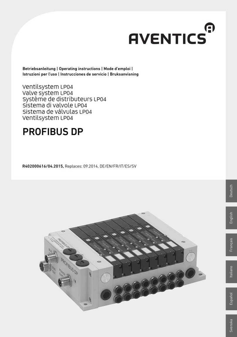
This manual applies to all standard versions of the valve
system (VS) LP04.
The LP04 is designed for space-limited automation
applications. Size is therefore prioritized over modularity.
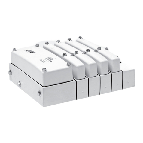
One VS can consist of 2*, 4, 6, 8, 10, 12, 14 or 16 valve
positions (* = only version 33–35). After delivery it is
extendable with one double sub-base (= 2 valve positions).
Note! Versions 33–35 and 80–81 are not extendable.
Fig. – shows the different available versions.
Design
The LP04 valve system is composed of the following
components:
WRight end plate for pneumatic connections.
W2–16 sub-bases for valves, blanking plates or air
supply plates.
WLeft end plate for pneumatic connection.
WConnection piece for electrical connections.
Valves
Directional-control valves complete with pilot control
valve. The valves have a manual override of turn and
detent type, (yellow knob) or, turn type (red knob).
Yellow LEDs for side 14 and side 12.
Pneumatic components
Spare parts and accessories are listed under section
„Spare parts“.
Electrical connection
The valve system is controlled via either Sub-D connection
or fieldbus connection. Available fieldbus protocols are
Profibus DP, CANopen, Device-Net and AS-i. Also the
fieldbus system Drive and Diagnostic Link (DDL) is available
with or without inputs.
Function
The valve system is connected to the pneumatic system
via two end plates for air supply and exhaust for both main
and pilot valves. Channel 1 supplies all valves with
compressed air. The pilots may be supplied with air either
from channel 1 (internal supply) or from an external pilot
air supply port (port X) on the right end plate. The exhaust
air from all main valves is evacuated through integrated
silencers or port 3/5 in the end plates.
The exhaust air from all pilot valves is evacuated through an
integrated silencer or through port Rx in the right end plate.
Air supply connections are provided on both sides of the
VS, through the two end plates (port 1). It is recommended
to connect the air supply lines to both sides.
The valves direct the air to the pneumatic drives. The
connection is made via the valve’s sub-base (sub-base
connection port 2 and 4).
SIGNAL WORD
Hazard type and source
Consequences of non-observance
OMeasures to avoid these hazards
NOTICE
Indicates damage to property: The product or its
environment may be damaged.
Operation may be impaired if this information is
disregarded.
Each valve has a manual override which is
activated by a turning motion. Do not push!
