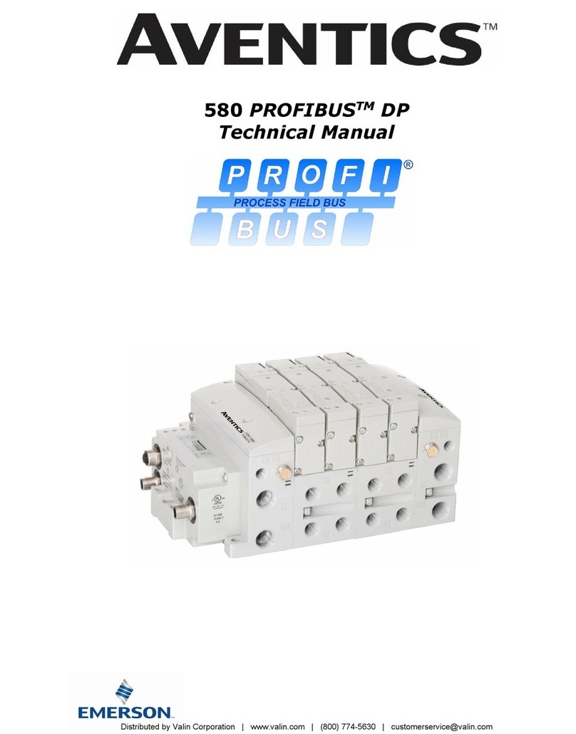
580 POWERLINKTM Technical Manual
1-4
TD580PLTM1-5EN 12/21
Subject to change without notice
http://www.Emerson.com
Table of Contents
PAGE
1. About POWERLINKTM........................................................................................................................................5
1.1 Overview ...............................................................................................................................................5
1.2 580 POWERLINKTM Features .....................................................................................................................5
2. 580 POWERLINKTM Introduction.........................................................................................................................6
2.1 Pneumatic Valve Manifold –501 Series shown............................................................................................7
2.2 500 Series Manifold Stations ....................................................................................................................8
2.3 Z-Board™ Connectors .............................................................................................................................9
3. Zoned Power.....................................................................................................................................................10
3.1 503 Series Zoned Power application ........................................................................................................10
3.2 503 Series Zoned Power example ...........................................................................................................11
4. Communication Module ......................................................................................................................................12
4.1 580 POWERLINKTM Node ........................................................................................................................12
4.2 580 Node Description ............................................................................................................................13
4.3 Connector Pin-Outs ...............................................................................................................................14
4.4 Electrical Connections............................................................................................................................15
4.5 Chassis Ground ....................................................................................................................................16
4.6 Power Consumption ..............................................................................................................................17
4.7 Recommended External Fuses ................................................................................................................18
4.8 Diagnostics –580 POWERLINKTM Node LED Functions................................................................................19
5. Extended Coil Capability .....................................................................................................................................20
5.1 500 Series Extended Coil Configurations ..................................................................................................20
5.2 500 Series Extended IO Mapping ............................................................................................................23
5.3 501 Series, up to 64 solenoid coils..........................................................................................................24
5.4 501 Series, up to 128 solenoid coils ........................................................................................................25
5.5 502 and 503 Series, up to 80 coils ..........................................................................................................26
6. 580 POWERLINKTM Node Graphic Display ..............................................................................................................27
6.1 IP Address Sub-Menu ............................................................................................................................28
6.2 Subnet Mask Sub-Menu .........................................................................................................................29
6.3 Gateway IP ..........................................................................................................................................30
6.4 Web Server Sub-Menu...........................................................................................................................30
6.5 Config. Mode........................................................................................................................................32
6.6 MAC Address Sub-Menu.........................................................................................................................33
6.8 Model Number Sub-Menu.......................................................................................................................33
6.9 Advanced Settings –Comm. Fault...........................................................................................................34
6.10 Advanced Settings - Brightness ..............................................................................................................35
5.12 Advanced Settings –Flip Display ............................................................................................................36
5.13 Advanced Settings –Parameters Lock .....................................................................................................37
5.14 Advanced Settings –Configuration Lock ..................................................................................................38
6.12 Factory Defaults ...................................................................................................................................39
6.13 Diagnostics ..........................................................................................................................................40
6.14 Diagnostics Self-Test.............................................................................................................................40
6.15 Messages Error Messages ......................................................................................................................42
7. POWERLINKTM Integrated Web Server ..................................................................................................................43
7.1 Connecting to an Aventics 580 PowerlinkTM Node ......................................................................................43
7.2 Using the Functionality of the 580 PowerlinkTM Web Server.........................................................................45
7.3 User Configurable Device Parameters ......................................................................................................52
7.4 Communication Fault/Idle Mode Parameter ..............................................................................................53
8. B&R Automation Studio and 580 Configuration ......................................................................................................54
8.1 Import the XDD File ..............................................................................................................................54
9. POWERLINKTM Mapping.......................................................................................................................................61
9.1 I/O Sizes .............................................................................................................................................61
9.2 Bit Mapping Rules .................................................................................................................................61
9.3 Mapping Example No. 1 .........................................................................................................................62
9.4 Mapping Example No. 2 .........................................................................................................................63
10. Appendix ........................................................................................................................................................64
10.1 System Specifications............................................................................................................................64
10.2 Factory Default Settings ........................................................................................................................64
10.3 Troubleshooting....................................................................................................................................65
10.4 Glossary of Terms.................................................................................................................................65
10.5 Technical Support .................................................................................................................................66
Distributed
by
Valin
Corporation
|
www.valin.com
|
(800)
774-5630
|
[email protected]