AVer PTZ211 User manual

Professional PTZ Camera
—User Manual —
PTZ211 / PTZ211N / PTZ310UV2 / PTZ310UNV2
PTZ231 / PTZ231N / PTZ330UV2 / PTZ330UNV2

Warning
To reduce the risk of fire or electric shock, do not expose this appliance to rain or moisture.
Warranty will be void if any unauthorized modifications are done to the product.
Do not drop the camera or subject it to physical shock.
Use the correct power supply voltage to avoid the damaging camera.
Do not place the camera where the cord can be stepped on as this may result in fraying or
damage to the lead or the plug.
Hold the bottom of the camera with both hands to move the camera. Do not grab the lens or lens
holder to move the camera.
Federal Communications Commission
NOTE: This equipment has been tested and found to comply with the limits for a Class A digital
device, pursuant to part 15 of the FCC Rules. These limits are designed to provide reasonable
protection against harmful interference when the equipment is operated in a commercial
environment. This equipment generates, uses, and can radiate radiofrequency energy and, if not
installed and used in accordance with the instruction manual, may cause harmful interference to
radio communications. Operation of this equipment in a residential area is likely to cause harmful
interference in which case the user will be required to correct the interference at his own
expense.
FCC Caution:Any changes or modifications not expressly approved by the party responsible for
compliance could void the user's authority to operate this equipment.
This device complies with part 15 of the FCC Rules.
Operation is subject to the following two conditions:
(1) This device may not cause harmful interference, and
(2) this device must accept any interference received, including interference that may cause undesired
operation.
This ClassA digital apparatus complies with Canadian ICES-003. Cet appareil numérique de la classe
A est conforme à la norme NMB-003 du Canada.

Warning
This is a class A product. In a domestic environment, this product may cause radio interference
in which case the user may be required to take adequate measures.
Caution
Risk of explosion if battery is replaced by an incorrect type. Dispose of used batteries according
to the instructions.
VCCI-A
この装置は、クラス A 機器です。この装置を住宅環境で使用すると電波妨害を引き起こすことがあります。こ
の場合には使用者が適切な対策を講ずるよう要求されることがあります。
사용자안내문
이기기는 업무용 환경에서 사용할 목적으로 적합성평가를 받은 기기로서 가정용 환경에서
사용하는 경우 전자파간섭의 우려가 있습니다.
※사용자 안내문은 "업무용 방송통신기자재"에만 적용됩니다.
기종별
사용자안내문
A급기기
(업무용 방송통신기자재)
이기기는 업무용(A 급) 전자파적합기기로서 판
매자 또는 사용자는 이점을 주의하시기 바라
며, 가정외의 지역에서 사용하는 것을
목적으로합니다.
DISCLAIMER
No warranty or representation, either expressed or implied, is made with respect to the contents
of this documentation, its quality, performance, merchantability, or fitness for a particular
purpose. Information presented in this documentation has been carefully checked for reliability;
however, no responsibility is assumed for inaccuracies. The information contained in this
documentation is subject to change without notice.
In no event will AVer Information Inc. be liable for direct, indirect, special, incidental, or
consequential damages arising out of the use or inability to use this product or documentation,
even if advised of the possibility of such damages.
TRADEMARKS
“AVer” is a trademark owned by AVer Information Inc. Other trademarks used herein for
description purpose only belong to each of their companies.
COPYRIGHT
© 2023 AVer Information Inc. All rights reserved. | August 31, 2023
All rights of this object belong to AVer Information Inc. Reproduced or transmitted in any form or
by any means without the prior written permission of AVer Information Inc. is prohibited. All
information or specifications are subject to change without prior notice.

More Help
For FAQs, technical support, software and user manual download, please visit:
Headquarters
Download Center: https://www.aver.com/download-center
Technical Support: https://www.aver.com/technical-support
USA Branch Office
Download Center: https://www.averusa.com/pro-av/support
Technical Support: https://averusa.force.com/support/s/contactsupport
Europe Branch Office
Download Center: https://www.avereurope.com/download-center
Technical Support: https://www.avereurope.com/technical-support
Contact Information
Headquarters
AVer Information Inc.
https://www.aver.com
8F, No.157, Da-An Rd., Tucheng Dist., New Taipei City 23673, Taiwan
Tel: +886 (2) 2269 8535
USA Branch office
AVer Information Inc., Americas
https://www.averusa.com
668 Mission Ct., Fremont, CA94539, USA
Tel: +1 (408) 263 3828
Toll-free: +1 (877) 528 7824
Technical support: support.usa@aver.com
Europe Branch office
AVer Information Europe B.V.
https://www.avereurope.com
Westblaak 134, 3012 KM, Rotterdam, The Netherlands
Tel: +31 (0) 10 7600 550
Technical support: eu.rma@aver.com
Japan Branch Office
アバー・インフォメーション株式会社
https://jp.aver.com
〒160-0023 日本東京都新宿区西新宿 3-2-26 立花新宿ビル 7 階
Tel: +81 (0) 3 5989 0290
テクニカル・サポート: https://jp.aver.com/technical-support
Vietnam Branch Office
Công ty TNHH AVer Information (Việt Nam)
Tầng 5, 596 Nguyễn Đình Chiểu, P.3, Quận 3,
Thành phốHồChíMinh 700000, Việt Nam
Tel: +84 (0)28 22 539 211

Contents
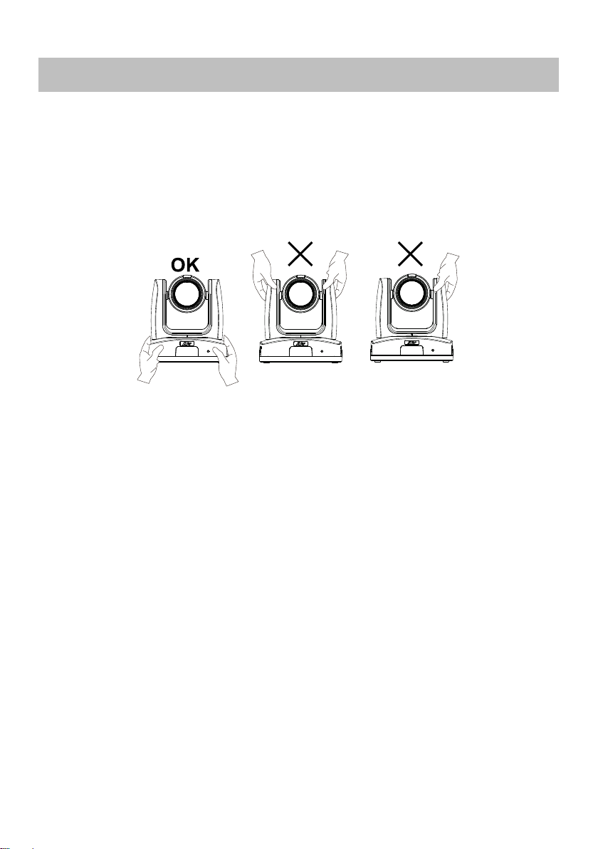
Warning...............................................................................................................................2
Overview .............................................................................................................................1
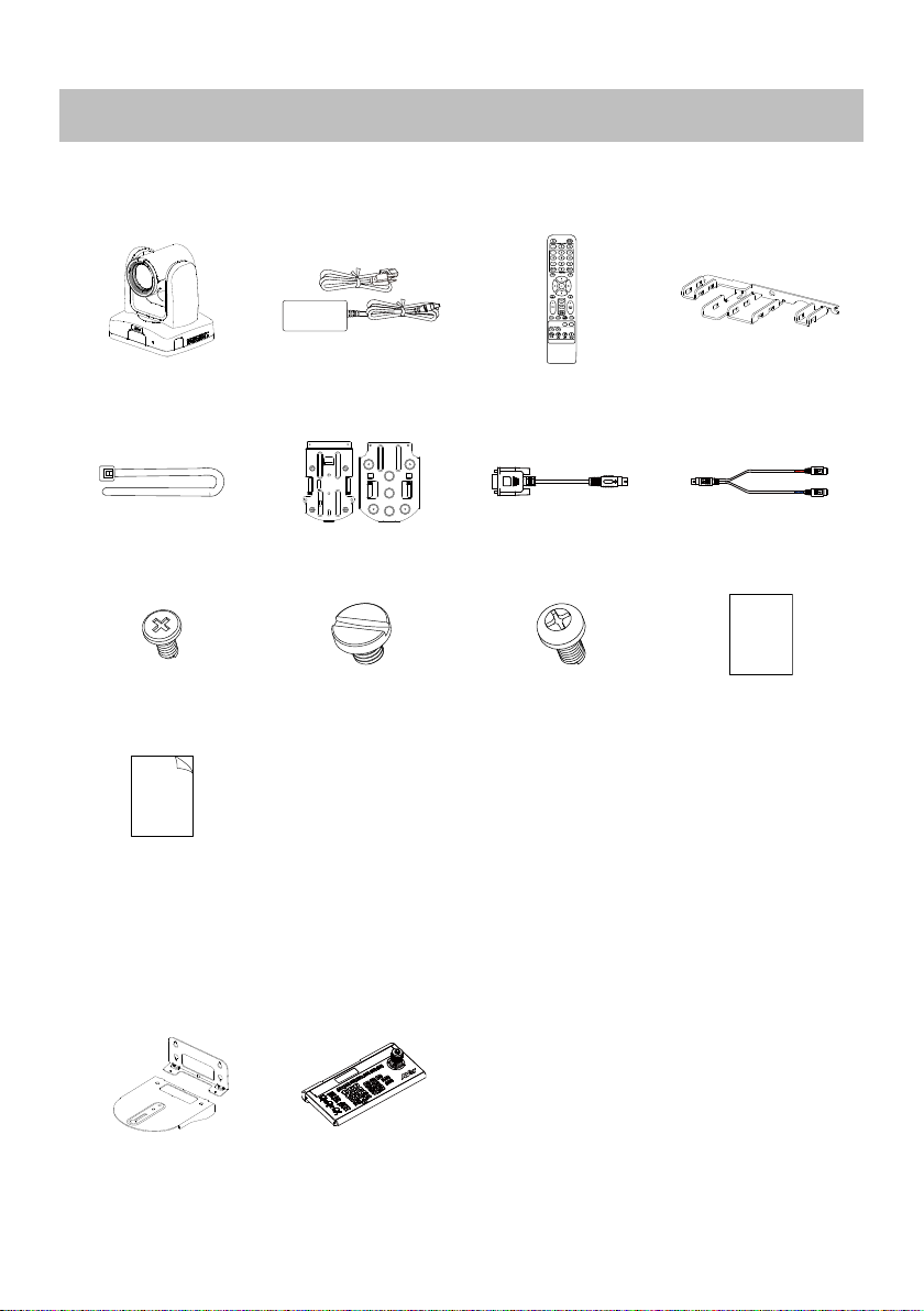
Package Contents ...........................................................................................................1
Optional Accessories*......................................................................................................1
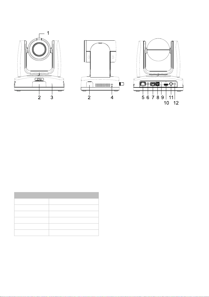
Parts Info.........................................................................................................................2
LED Indicators ............................................................................................................2
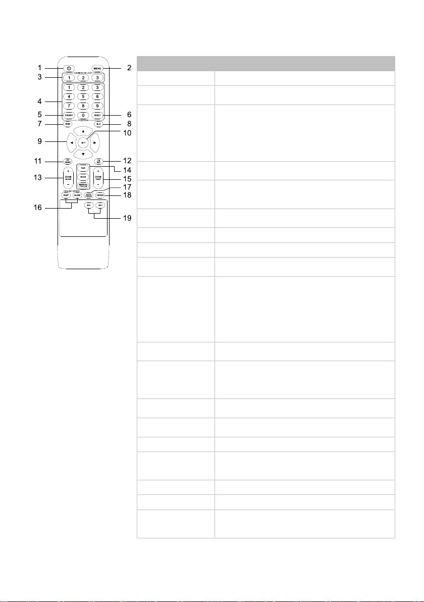
Remote Control................................................................................................................3
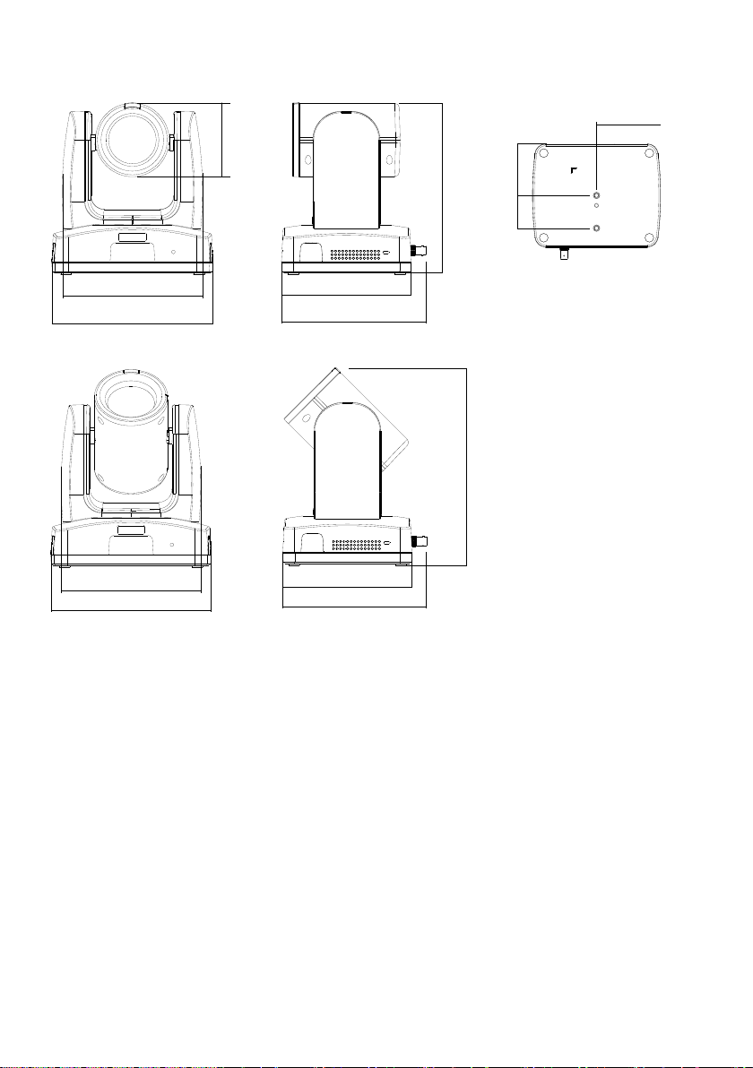
Dimensions......................................................................................................................4
Pan and Tilt Angle............................................................................................................6
Connection..........................................................................................................................7
Device Connection...........................................................................................................7
PoE Connection...............................................................................................................7
RS-232 and RS-422 Connection .....................................................................................9
Audio Input Connection .................................................................................................14
Video Output Connection...............................................................................................15
Installation ........................................................................................................................16
Cable Fixing Plate Installation .......................................................................................16
Ceiling Mount Installation...............................................................................................17
Camera Installation........................................................................................................18
Set Up the Camera............................................................................................................19
OSD Menu.....................................................................................................................19
IP Address Setup...........................................................................................................19
Static IP ....................................................................................................................19
DHCP........................................................................................................................20
OSD Menu Tree.............................................................................................................21
Camera.....................................................................................................................21
Video Output.............................................................................................................23

Network.....................................................................................................................23
Advanced Setting......................................................................................................23
System......................................................................................................................24
Web Setup.........................................................................................................................25
Access the Web Interface of the Camera......................................................................25
Accessing the Camera via AVer IPCam Utility ..........................................................25
Accessing the Camera via AVer PTZ Management ..................................................26
Live View .......................................................................................................................27
Camera Control.........................................................................................................27
Preset .......................................................................................................................28
Camera Settings............................................................................................................29
Exposure...................................................................................................................29
Image Process..........................................................................................................30
Video & Audio................................................................................................................31
Network .........................................................................................................................33
Advanced Setting...........................................................................................................36
SmartShoot...............................................................................................................36
SmartFrame..............................................................................................................37
Debug Information ....................................................................................................38
NDI (model names with N only).....................................................................................39
System...........................................................................................................................41
Appendix...........................................................................................................................43
VISCA RS-232 Command Table....................................................................................43
Visca over IP Settings....................................................................................................48
CGI Command...............................................................................................................49

Overview
Package Contents
Camera
Power Adapter &
Power Cord*
Remote Control
Cable Fixing Plate
Cable Tie (x4)
Ceiling Mount
Bracket (x2)
DIN8 to D-Sub9
Cable
RS-232 In/Out
Y Cable
M2 x 4mm
Screw (x3)
1/4”-20, L=6.5mm
Screw (x2)
M3 x 6mm
Screw (x3)
Drill Template
Quick Start Guide
*The power cord may vary based on the country or region where sold.
Optional Accessories*
Wall Mount Bracket
Camera Controller
(CL01)
*For details on optional accessories, please consult with your local dealer.

2
Parts Info
1. Tally Lamp
2. IR Sensor
3. LED Indicator
4. Kensington Lock
5. PoE+ IEEE 802.3AT
6. RS-232 Port
7. RS-422 Port
8. USB 3.0 Type-B Port
9. Audio In*
10. HDMI Port
11. 3G-SDI (unavailable for
model names with H)
12. DC Power Jack
*Line input: 1Vrms max.
Mic input level: 50mVrms max.; supplied voltage: 2.5V.
LED Indicators
Color
Status
Solid blue
Normal
Flashing red
Firmware update
Solid orange
Standby
Flashing orange
Start-up
Flashing purple
SmartShoot
Flashing blue
SmartFrame

3
Remote Control
AAA Battery (x2)
(not included)
Name
Function
1. Power
Power on or enter standby mode.
2. Menu
Open and close the OSD menu during HDMI
output.
3. Camera
Select
No selection is required by default to operate
the camera.
Both camera and remote control have
been set to 1.
Specify a number in the OSD menu:
System > Camera Selector.
4. Number Pad
Press number button (0-9) to move the camera
to pre-configured preset position 0-9.
5. Preset
Press and hold Preset, then short press
Number button (0-9) to save the preset
position.
6. Reset
Press and hold Reset, then short press Number
button (0-9) to reset preset position.
7. WDR
Turn Wide Dynamic Range on or off.
8. BLC
Turn Backlight Compensation on or off.
9. Directional
Buttons
Press once for incremental movement or press
and hold for continuous pan or tilt.
10. Enter
Confirm a selection in the OSD menu.
Short press to turn on One Push Focus.
Press and hold for 2 seconds to turn on
SmartFrame.
Note: Make sure SmartFrame has been
turned on in the OSD menu or on the web
interface for this shortcut to work.
11. PT Reset
Return the Pan-Tilt position to the home
position.
12. L/R SET
Invert L/R Pan Direction: Press and hold
L/R SET, then short press Position 2.
Reset L/R Pan Direction: Press and hold
L/R SET, then short press Position 1.
13. Zoom Slow
+/-
Zoom in or out slowly.
14. Far / Near /
Manual Focus
Enable manual focus. Use Far/Near to adjust
the focus.
15. Zoom Fast +/-
Zoom in or out fast.
16. Pan-Tilt
Speed Fast /
Slow
Adjust pan-tilt speed.
17. Auto Focus
Autofocus.
18. Freeze
Freeze the live view.
19. EV +/-
Short press to adjust EV level.
Long press EV+ to turn on RTMP.
Long press EV- to turn off RTMP.

4
Dimensions
156.5mm
180mm
82mm
145mm
161.3mm
191.5mm
46mm 72.5mm
80mm
156.5mm
180mm
145mm
161.3mm
216mm

5
Ceiling Mount
153mm
180mm
161.3mm
200.8mm
80mm
104mm
35mm
112mm

6
Pan and Tilt Angle
180mm
206mm
161.3mm
263.2mm
Wall Mount
35.8mm
259.7mm

7
Connection
Device Connection
PoE Connection
Connect the camera to the router or switch through the PoE+ port.
[Note] Only support IEEE 802.3AT PoE+ standard.
Lecture capture system
Professional PTZ Camera
3G-SDI
PoE+
HDMI
or
or
LAN
(Record)
Laptop
(Management/Presentation)
Monitor/TV
(Display)
Web application
(Remote Management)
Microphone
Audio input RS-232
or
RS-422
Joystick
(Camera control)

8
Router/PoE Switch
Ethernet Cable
(Not Included)

9
RS-232 and RS-422 Connection
Connect through the RS-232 or RS-422 for camera control.
RS-232
Laptop
Joystick
RS-232 (VISCA) cable
(Not included)

10
RS-232 Port Pin Definition
Function
Mini DIN9
PIN #
I/O Type
Signal
Description
VISCA IN
1
Output
DTR
Data Terminal Ready
2
Input
DSR
Data Set Ready
3
Output
TXD
Transmit Data
6
Input
RXD
Receiver Data
VISCA OUT
7
Output
DTR
Data Terminal Ready
4
Input
DSR
Data Set Ready
8
Output
TXD
Transmit Data
9
Input
RXD
Receiver Data
5
Input
I/O
Detect DIN8/DIN9
---
Shield
---
GND
Ground
1
2
3456
789

11
RS-232 mini DIN9 to mini DIN8 Cable Pin Definition
Mini DIN8 Cable Pin Definition
12 34
56
7
8
No.
Signal
1
DTR
2
DSR
3
TXD
4
GND
5
RXD
6
GND
7
NC
8
NC

12
Din8 to D-Sub9 Cable Pin Definition
6 7 8
3 4 5
1 2
15
69

13
RS-422
[Note] Use cat5e splitter for multi-camera connection.
Cat5e splitter pin assignment:
1
234
5
678
1
234
5
678 1
234
5
678
Camera
Camera/Joystick Camera/Joystick
RS-422 Pin
No.
Pin
No.
Pin
1
TX+
5
TX-
2
TX-
6
RX-
3
RX+
7
RX+
4
TX+
8
RX-
1 8

14
Audio Input Connection
Connect the audio device for audio receiving.
[Note]
- Line input level: 1Vrms (max.).
- Mic input level: 50mVrms (max.); Supplied voltage: 2.5V.
Microphone
Audio Mixer
This manual suits for next models
7
Table of contents
Other AVer Security Camera manuals

AVer
AVer FD2000 User manual

AVer
AVer TR320NV2 User manual

AVer
AVer PAVPTR310 User manual

AVer
AVer PTC300V2 Series User manual

AVer
AVer FC2020-PW User manual

AVer
AVer FB3028-RT1 User manual

AVer
AVer SF2012H-D User manual

AVer
AVer FC2020-P Instruction manual

AVer
AVer VC322 User manual

AVer
AVer CAM520 Pro User manual