AVLink SX-2088 User manual

User Manual
SX-2044 SX-2084
SX-2088
SX Series Matrix Switching Systems

SX Matrix Switching System—User Manual
1
Before You Use the System
1、Read manual——Carefully read the manual before you use the system.
2、Installation environment——The system should be installed indoor only. Install either on a
sturdy rack or desk in a well-ventilated place.
3、Lightning——Unplug the power cord during lightning or after a prolonged period of non-use
to avoid damage to the equipment.
4、Maintenance——Only qualified technical engineers or specified distributors are permitted to
repair or replace components and parts of the equipment upon failure.

SX Matrix Switching System—User Manual
2
Table of Contents
1.0 Matrix System Overview…………………………………….……………………………...4
1.0.1 SX Matrix System……………………………………………………………..…….….4
1.0.2 SX Matrix System Packing……………………………………………………..……....4
2.0 SX Matrix Host Installation…………………………………………………………...….....5
3.0 SX Matrix System Models………………………………………………………..……........6
4.0 Matrix System Front and Rear Panels…………………………………………...…………..6
4.0.1 SX-3044 Front and Rear Panels.......................................................................................6
4.0.2 SX-3084 Front and Rear Panels…………………………………………………….......7
4.0.3 SX-3088 Front and Rear Panels…………………………………………………...........7
5.0 SX Matrix System and Perpherals Connection………………………………………..….....8
5.0.1 Input/Output Ports………………………………………………………….…………...8
5.0.1.1 Audio Connecting Cable……………………………………………………..….....8
5.0.2 SX Matrix System and Control Computer Connection………………………………...10
5.0.3 Remote Control and Settings……………………………………………………….......10
5.0.3.1 RS-232 Communication Port and Connection……………………………..…........10
5.0.3.2 RS-485 Communication Port…………………………………………………........12
5.0.3.3 On/Off Switch Settings…………………………………………………………….13
5.0.3.4 SX Matrix System and Control System Connection……………………………….15
6.0 Matrix System Control Panel Operation………………………………………………….…17
6.0.1 Input/Output Switching Key Operating Mode…………………………………….........17
6.0.2 Front Panel Key Function…………………………………………………………........17
6.0.3 Operation Examples…………………………………………………………………….19
7.0 Matrix Application Software…………………………...……………………………………21
7.0.1 Software Introduction……………………………….……………………………..……21
7.0.1.1 Software Description……………………………………………………….………21
7.0.1.2 Software Activation………………………………………………………….…......22
7.0.2 Software Features……………………………………………………………….………22
7.0.2.1 Main Operating Interface Features………………………………………….……...23
7.0.2.2 Disconnect Function Key………………………………………………….….........25
7.0.2.3 Select all output、DeSelect all output Switching Function Usage…………...........26
7.0.2.4 Disconnect all Command…………………………………………………………..26
7.0.2.5 Memory Function Usage……………………………………………………...........27
7.0.2.6 Scan Function Usage…………………………………………………………….…27
7.0.2.7 Options Function Applications….…………………………………………….........27
7.0.2.8 Exit Function Applications…………………………………………………….…...28
7.0.2.9 Other Applications…………………………………………………………….…....28
8.0 Communication Protocol and Control Command Code……………………………………..28

SX Matrix Switching System—User Manual
3
9.0 SX Matrix System Technical Parameters………………………….…….………..……….29
10.0 Common Problems and Solutions……………………………….……………………….30

SX Matrix Switching System—User Manual
4
1.0 Matrix System Overview
1.0.1 SX Matrix System
The SX Matrix switcher is a high performance switching equipment for S-Video and audio
frequency. It is used for input/output cross switching of multi-video and audio frequency signals.
It provides separate video and audio jacks for separate transmission of each video frequency
component signal and audio frequency signal, thereby minimizing signal attenuation and
ensuring high definition and high fidelity graphics and audio signal output.
The SX Matrix is used mainly in TV broadcasting projects, multi-media conference halls,
large display projects, TV teaching and command control centers. It boasts features of power
interruption protection during power surge, LCD display and synchronous and separate
audio/visual switching functions. Its RS-232 communication port enables convenient
communication with remote control equipment. This manual describes using of the SX-2088
model. Refer to SX-2088 User Manual for using of other models of matrix systems.
Figure 1-1 SX-2088 Matrix
1.0.2 SX Matrix System Packing
SX Matrix Host
RS-232 Communication Connection Cable

SX Matrix Switching System—User Manual
5
Power Cord
SX Matrix Testing and Application Software CD
User Manual
2.0 SX Matrix Host Installation
The SX Series Matrix Host has a black metallic housing. It can be placed on a sturdy desk or
installed on a 19-in rack. See Figure 2-1 below:
Figure 2-1 Installing the SX Matrix Host on a Standard Rack
Green Terminal(M)Quantity
SX-2044 2 Pcs
SX-2084 2 Pcs
SX-2088 2 Pcs
SX Matrix Switching System—User Manual
6
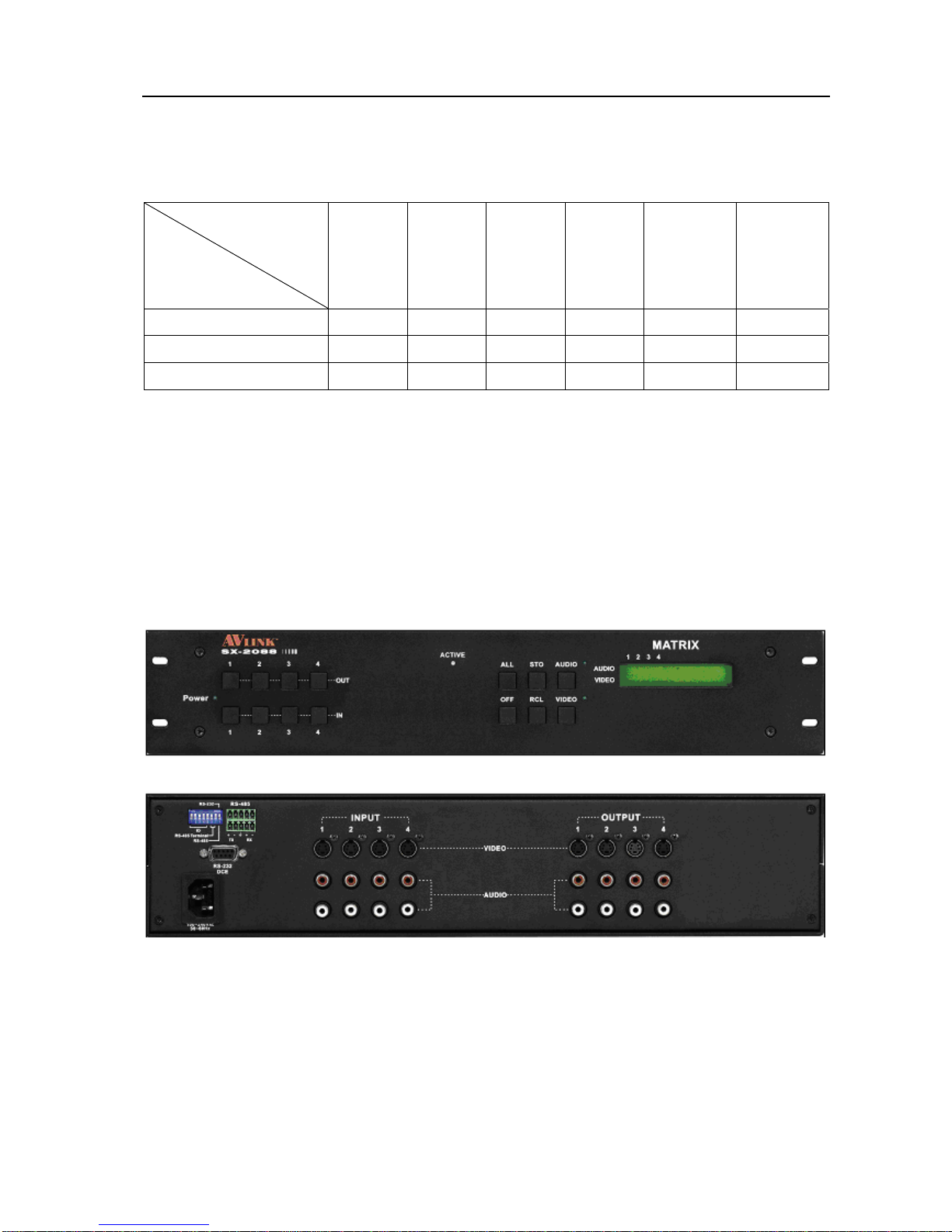
3.0 SX Matrix System Models
The SX Series Matrix has following models to meet different requirements of different users:
Technical
Parameters
Model
Video
Input
Port
Video
Output
Port
Audio
Input
Port
Audio
Output
Port
RS-485
Connector
RS-232
Connector
SX-2044 4 4 4 4 √ √
SX-2084 8 4 8 4 √ √
SX-2088 8 8 8 8 √ √
4.0 Matrix System Front and Rear Panels
4.0.1 SX-2044 Front and Rear Panels
Figure 4-1 SX-2044 Front Panel
Figure 4-2 SX-2044 Rear Panel
SX Matrix Switching System—User Manual
7
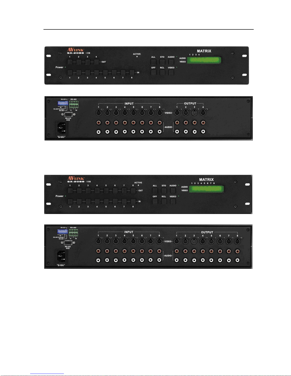
4.0.2 SX-2084 Front and Rear Panels
Figure 4-3 SX-2084 Front Panel
Figure 4-4 SX-2084 Rear Panel
4.0.3 SX-3088 Front and Rear Panels
Figure 4-5 SX-2088 Front Panel
Figure 4-6 SX-2088 Rear Panel
SX Matrix Switching System—User Manual
8
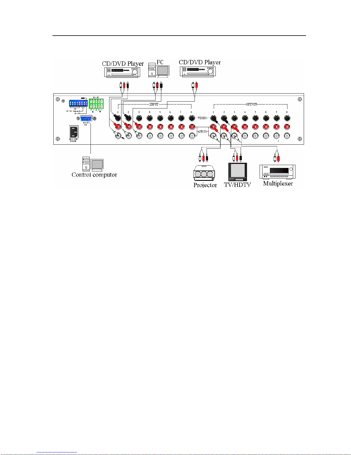
5.0 SX Matrix System and Peripherals Connection
Figure 5-1 SX Matrix System Connection
5.0.1 Input/Output Jacks
Referring to the different models, the video signal input/output jacks are formed by the 4th
row and 8th row S-Video and RCA female terminals. Lining from the top to the bottom are
respectively video and audio signal terminals. The video signal terminals are S-Video, the audio
signal terminals are red (right audio channel) and white (left audio channel). Channels of the
output terminals are numbered from left to right from 1 to 8. Refer to the drawing on the housing
for port terminals of different models.
Different models of the SX matrix system provides a different number of input/output jacks
for users to connect to different audio/visual equipment including CD/DVD players, graphics
workstations, and number displays. The output terminals can be connected to projectors, video
recorders, displays and multiplexers and so on.
5.0.1.1 Audio Connecting Cable
Different models of the SX matrix system provides a different number of input/output jacks
for users to connect to different audio/visual equipment including CD/DVD players, graphics
workstations, and number displays. The output terminals can be connected to projectors, video
recorders, displays and multiplexers and so on.
S-Video video connector is a standard (Y/C)Min-din 4PIN connector.
RCA audio connector is a pair of (R/L) female RCA connectors.
The SX Matrix supports various AV signal sources.
SX Matrix Switching System—User Manual
9
AV Connector—standard AV Input (S-Video/RCA)Connector:
Type: Audio connectors are in pairs (left/right channels) (white/red) and video connector
(S-Video)
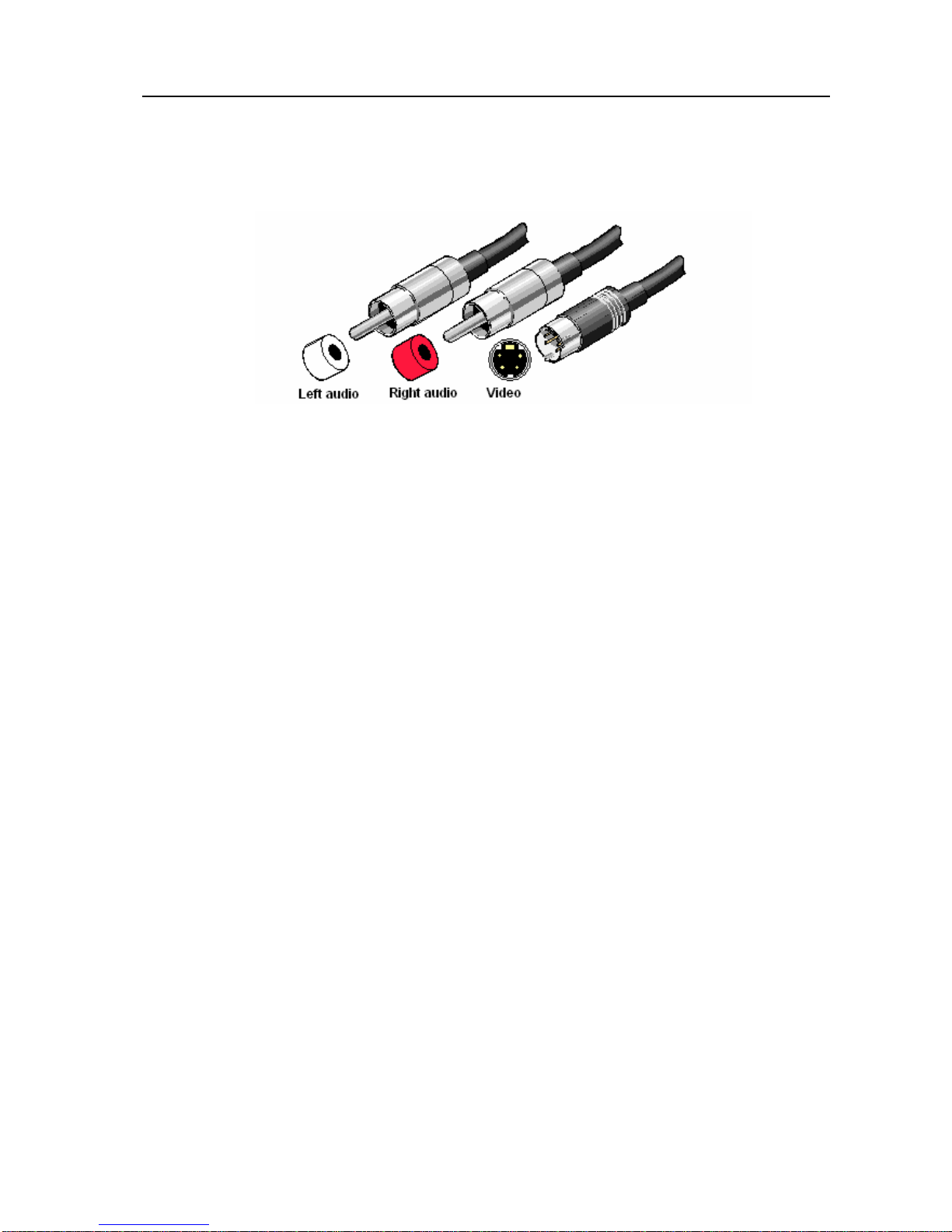
SX matrix RCA and S-Video connection, see Figure 5-2 below:
Figure 5-2 RCA and S-Video Connection
Generally, the RCA audio terminals are indicated in pairs by different colors: the right audio
channel uses red color (or use the letter “R” to indicate “Right”); the left audio channel is usually
black or white. Generally speaking, the RCA stereo cable is one cable to contain both left and
right audio channels.
Advantages: TheAV connector realizes separate transmission of audio and video frequencies,
thereby averting decline of graphics quality due to audio/video interference. Presently, almost
every TV set provides this connector for video input.
Connection method: Use the RCA-type socket for connection. Connect the video S-Video and
audio RCA (R/L) connectors of the output terminal of the signal source equipment respectively
to the same SX matrix input channel and connect the SX output via dedicated video S-Video and
audio RCA (R/L) signal lines to the video S-Video and audio RCA (R/L) input connectors of the
output equipment.
NOTE: The RCA(R/L) connectors at both ends of the signal lines must correspond to each
other, otherwise signals on the R/L audio channels would be reversed.
Audio Connecting Cable:
The “Audio Input” and “Audio Output”jacks of the SX matrix can be used to connect a video
recorder and a multiplexer respectively.
The audio cable branches into left and right audio channels. The red RCA represents the right
audio channel and the white RCA represents the left audio channel.
SX Matrix Switching System—User Manual
10
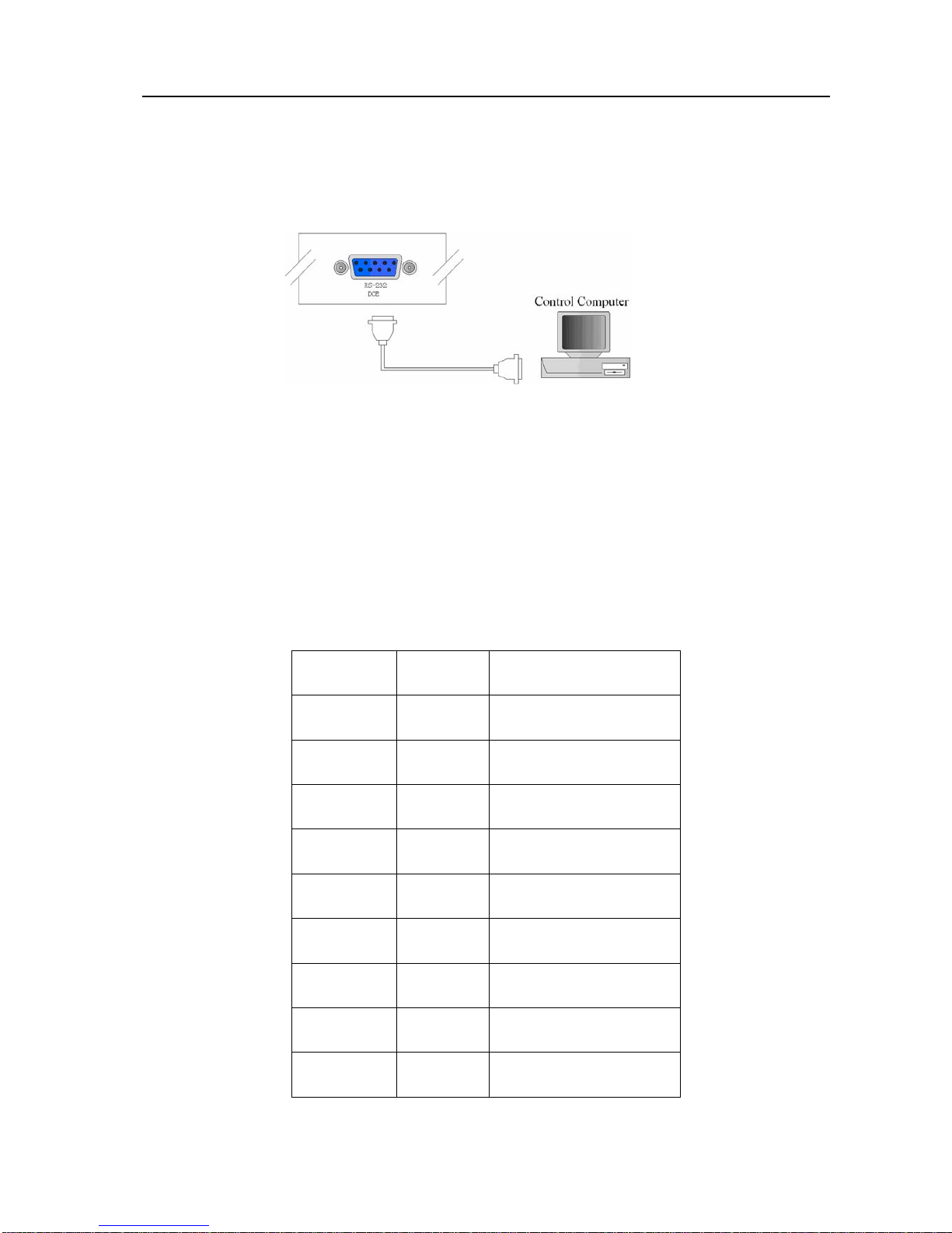
5.0.2 SX Matrix System and Control Computer Connection
Use the RS-232 connecting cable to connect the computer serial port (COM1 or COM2) to the
RS-232 communication port of the SX matrix host. The computer can then be used to control the
SX matrix after installation of application software.
Figure 5-4 SX Matrix and Computer Connection
5.0.3 Remote Control and Settings
The SX matrix provides standard RS-232 and RS-485 serial communication ports. Aside from
using the front panel keys for switching operation, you are also permitted to use the RS-232 and
RS-485 serial communication ports for remote operation. It also supports RS-485 serial control.
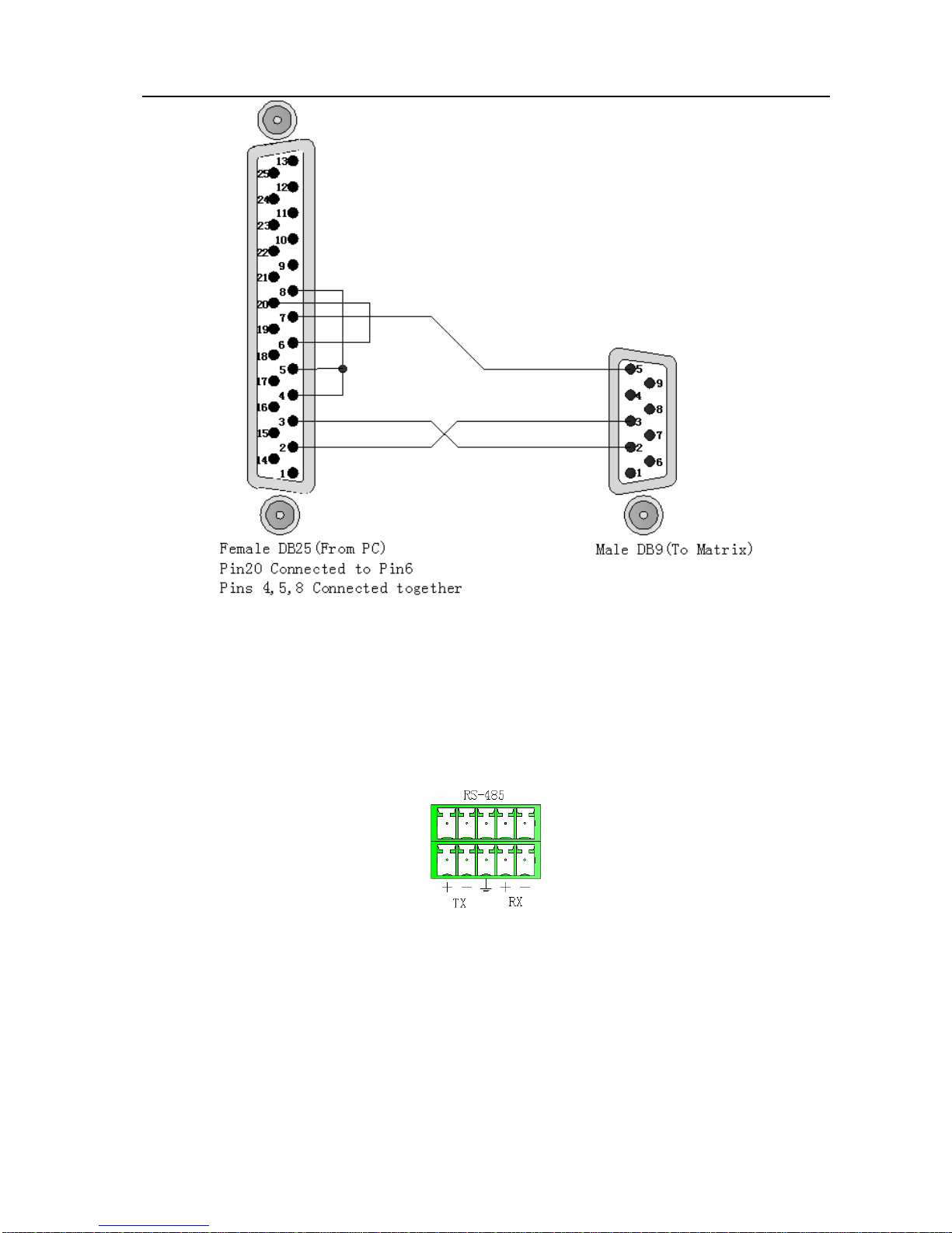
5.0.3.1 RS-232 Communication Port and Connection
The RS-232 port is a 9-pin female connector. The Leg functions are shown in the table below:
Pin No. Leg Description
1 N/u Null
2 Tx Send
3 Rx Receive
4 N/u Null
5 Gnd Ground
6 N/u Null
7 N/u Null
8 N/u Null
9 N/u Null

SX Matrix Switching System—User Manual
11
Figure 5-5
Figure 5-5(a)
SX Matrix Switching System—User Manual
12
Figure 5-6
Note: The Matrix RS-232 port is defined as DCE.
5.0.3.2 RS-485 Communication Port
You can use the RS-485 port to control more than one SX product.
The RS-485 Port as shown in Figure 5-7 below:
Figure 5-7

SX Matrix Switching System—User Manual
13
5.0.3.3 On/Off Switch Settings
Figure 5-8
A. DIP SW-8:RS-232/RS-485 switches ON/OFF
ON:RS-232 Enables Single System or RS-485 Serial Master
OFF:RS-485 Enables RS-485 Serial Slave
B. DIP sw-6/7:RS-485 Terminator ON/OFF
ON:TerminatorON
OFF:TerminatorOFF
C. DIP sw 1 to 5 Setting(address setting)
The ID address determines the position of a SX Matrix system. When multiple SX products
are connected to one PC or when the Matrix products are serially connected, the ID address
decides which SX product is to be controlled. Use the on/off switches 1, 2, 3, 4, 5 on the rear
panel to set the ID address as shown in Figure 5-2 below:

SX Matrix Switching System—User Manual
14
On/Off Switching PositionsID Address
(Decimal)Software ID
Address
(Hexadecimal)
On/Off
(Binary)SW1 SW2 SW3 SW4 SW5
0 00 00000 OFF OFF OFF OFF OFF
1 01 00001 OFF OFF OFF OFF ON
2 02 00010 OFF OFF OFF ON OFF
3 03 00011 OFF OFF OFF ON ON
4 04 00100 OFF OFF ON OFF OFF
5 05 00101 OFF OFF ON OFF ON
6 06 00110 OFF OFF ON ON OFF
7 07 00111 OFF OFF ON ON ON
8 08 01000 OFF ON OFF OFF OFF
9 09 01001 OFF ON OFF OFF ON
10 0A 01010 OFF ON OFF ON OFF
11 0B 01011 OFF ON OFF ON ON
12 0C 01100 OFF ON ON OFF OFF
13 0D 01101 OFF ON ON OFF ON
14 0E 01110 OFF ON ON ON OFF
15 0F 01111 OFF ON ON ON ON
16 10 10000 ON OFF OFF OFF OFF
17 11 10001 ON OFF OFF OFF ON
18 12 10010 ON OFF OFF ON OFF
19 13 10011 ON OFF OFF ON ON
20 14 10100 ON OFF ON OFF OFF
21 15 10101 ON OFF ON OFF ON
22 16 10110 ON OFF ON ON OFF
23 17 10111 ON OFF ON ON ON
24 18 11000 ON ON OFF OFF OFF
25 19 11001 ON ON OFF OFF ON
26 1A 11010 ON ON OFF ON OFF
27 1B 11011 ON ON OFF ON ON
28 1C 11100 ON ON ON OFF OFF
29 1D 11101 ON ON ON OFF ON
30 1E 11110 ON ON ON ON OFF
31 1F 11111 ON ON ON ON ON
Figure 5-2 ID Number Setting Table

SX Matrix Switching System—User Manual
15
5.0.3.4 SX Matrix System and Control System Connection
A. If your PC provides RS-232,please follow connection as shown in Figure 5-9 below:
Figure 5-9
NOTE: 1. RS-232 connection refer to previous Figure for operation;
2. RS-232 or RS-485 baud rates: 9600bps, no odd or even calibration address,8bit data
transmission address,1bit stop address(96,N,8,1);
3. Serial connection between Matrix RS-485 as follows:
TX(+)TX(+)
TX(-)TX(-)
RX(+)RX(+)
RX(-)RX(-)
4. Each DIP sw1-5 address must not set to same ID number.
SX Matrix Switching System—User Manual
16
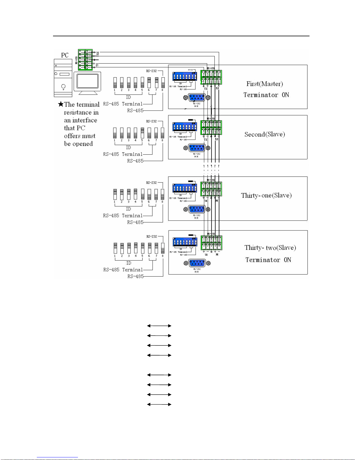
B. If your PC provides RS-485,please follow conection as shown in Figure 5-10 below:
Figure 5-10
NOTE: 1. RS-485 baud rate: 9600bps, no odd or even calibration address,8bit data transmission
address,1bit stop address(96,N,8,1);
2. Connect your PC RS-485 port to the Matrix RS-485 port as follows:
TX(+)TX(+)
TX(-)TX(-)
RX(+)RX(+)
RX(-)RX(-)
3. Serial connection between Matrix RS-485 ports as shown below:
TX(+)TX(+)
TX(-)TX(-)
RX(+)RX(+)
RX(-)RX(-)
4. Each DIP sw1-5 address must not set to same ID number.
SX Matrix Switching System—User Manual
17
6.0 Matrix System Control Panel Operation
6.0.1 Input/Output Switching Key Operating Mode
Fast audio/video switching of the Matrix systems can be done by pressing keys on the front
panel (refer to the “Front Panel Key Pressing Instructions” for detail key pressing.)
Operation methods as follows:
“Switching Method"+“Output Channel"+“Input Channel"
Follow instructions below:
“Switching Method"
For synchronous audio/video switching or alternative switching, select “Synchronous
Audo/Video Switching,” “Audio Switching” or “Video Switching” as per “Audio” and “Video”
keys.
“Output Channel"
The “OUT Row 1-8” keys on the front panel represent output channels 1 to 8 for connection to
peripheral display equipment.
“Input Channel"
The “IN Row 1-8” keys on the front panel represent input channels 1 to 8 for connection to the
currently connected channels of the signal source to be switched.
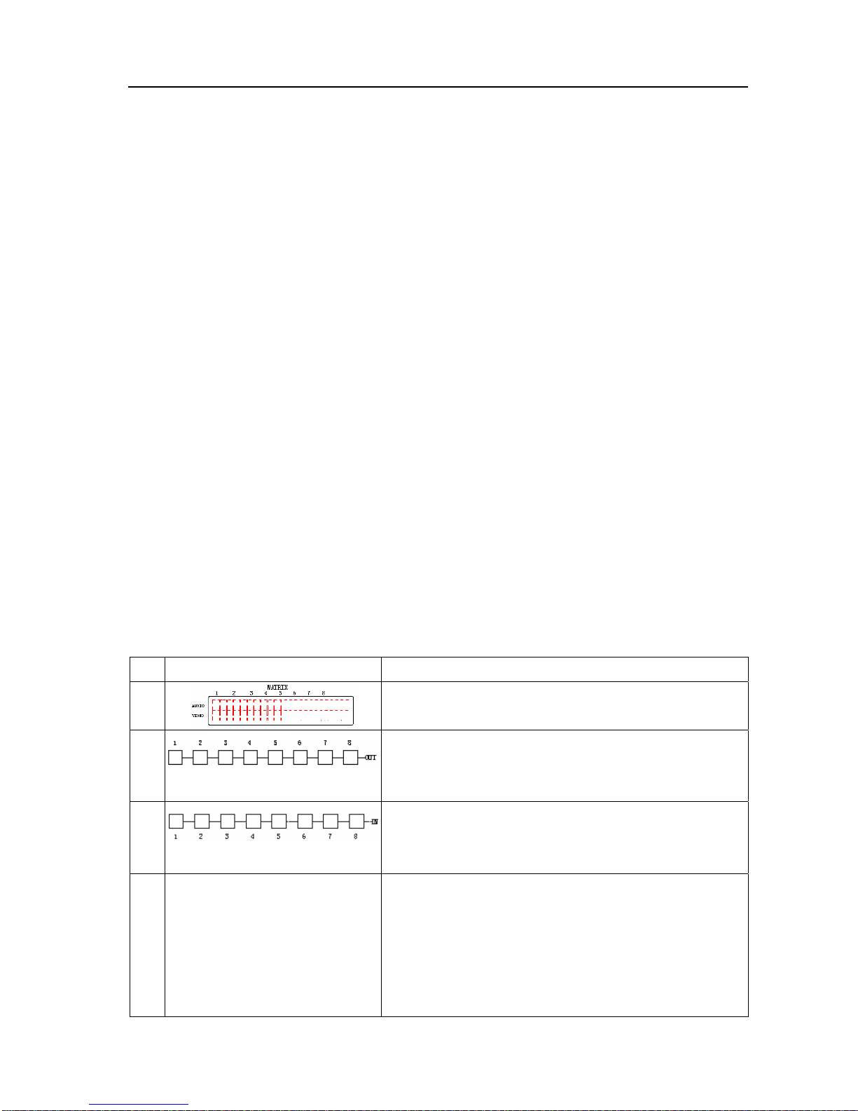
6.0.2 Front Panel Key Functions
Part Function Key Function
1
LCD display shows current SX matrix status and
operation hints.
2 Output channel selection keys used for setting
audio/video output channels or for selection of Status
Retrieve or Stored Number.
3 Input channel selection keys used for setting audio/video
output channels or for selection of Status Retrieve or
stored Number.
4
ALL
Implement all output selection keys via certain input
route.
---Example: First press the “ALL” key, then select the
input channel to output to all output channels; first press
the “ALL”key, then press the “OFF”key to close all the
presently displayed swtitching status.

SX Matrix Switching System—User Manual
18
Part Function Key Function
5
OFF
Close output channel key.
---First press to close the output channels, then press the
“OFF” key to close the specified channel.
6
STO
The “Reserve Key” saves all current input/output
corresponding relations.
---Example: Press the “STO”key, then press the output
channel key which you want to save to save all currently
displayed input/output corresponding relations.
7
RCL
The “Retrieve Key” retrieves the saved input/output
corresponding relations.
---Example: First press the “RCL” key, then press the
previously saved output channel key to retrieve the saved
input/output status and implement this status switching.
8
AUDIO
The audio switching selection key switches to another
output channel from the same channel.
Example: Press the Audio key to open or close the Audio
switching function. When the LED indicator to the left
of the Audio key lights shows switching function is open
and when the light goes off shows you have selected to
close the audio switching function.
9
VIDEO
The video switching selection key switches to another
output channel from the same channel.
Example 1: Press the Video key to open or close the
video switching function. When the LED indicator to the
left of the Vedio key shows video switching function is
open and when the light goes off shows the switching
function is close.

SX Matrix Switching System—User Manual
19
6.0.3 Operation Examples
Examle 1: Synchronously switch the NO.1 audio/video signal to the NO.3 and 4 output
channels. Key LCD Display Operation
1. Press the NO.3 key of the
output channel for 2
seconds, then enter the input
channel when the red 0 on
LCD begins to flicker.
2. Press the NO.1 key of the
Input channel for 2 seconds
for selection of NO.1
channel to input into NO.3
channel for output. The LCD
shows 1 at channel NO.3 for
both Audio and Video. Enter
the Output channel.
3. Press the NO.4 key of the
output channel for 2 seconds
and then enter the input
channel when the red 0 on
LCD flickers.
4. Press the NO.1 key of the
input channel for 2 seconds
for selection of NO.1
channel for input and NO.3
and 4 channels for output.
LCD shows 1 at NO.3 and
NO.4 channels for both
Audio and Video.
This manual suits for next models
2
Table of contents
Other AVLink Matrix Switcher manuals

AVLink
AVLink YX-3044 User manual

AVLink
AVLink HX-2344 User manual

AVLink
AVLink VX-2088 User manual

AVLink
AVLink HX-2384Z User manual

AVLink
AVLink SD-1 User manual

AVLink
AVLink HX-2544 User manual

AVLink
AVLink 128.850UK User manual

AVLink
AVLink HX-2388 User manual

AVLink
AVLink MX-3UB User manual

AVLink
AVLink HX-2344Z User manual


