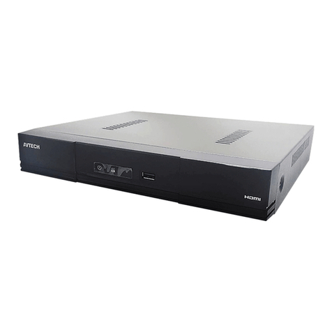
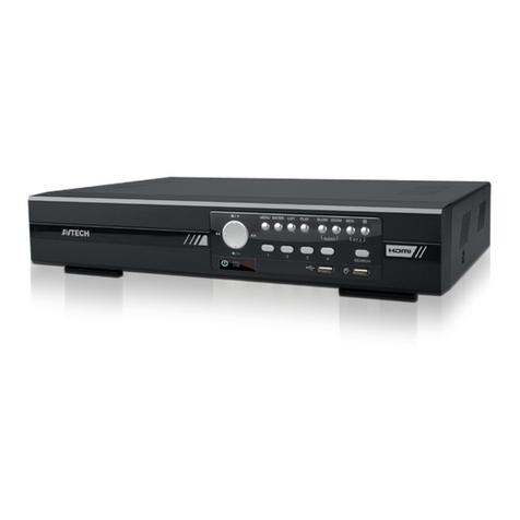
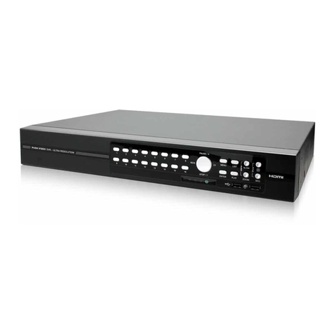
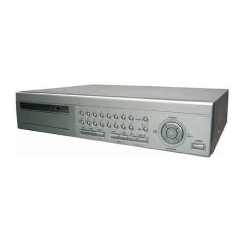
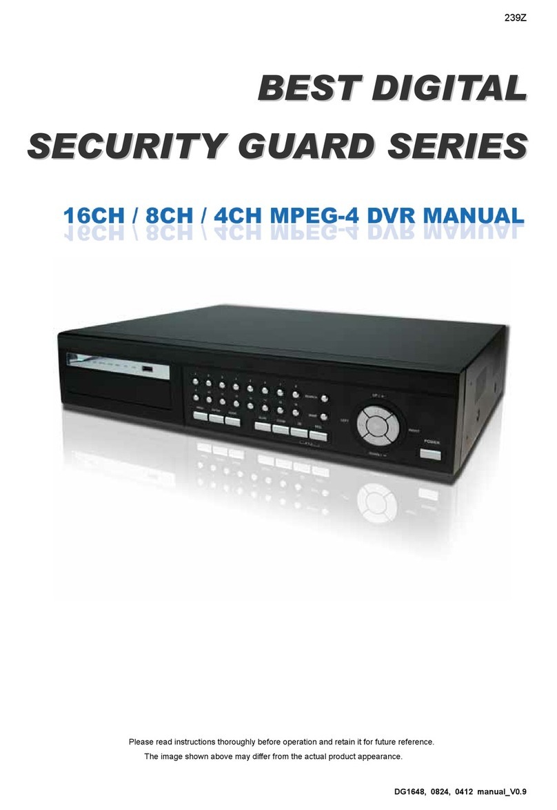
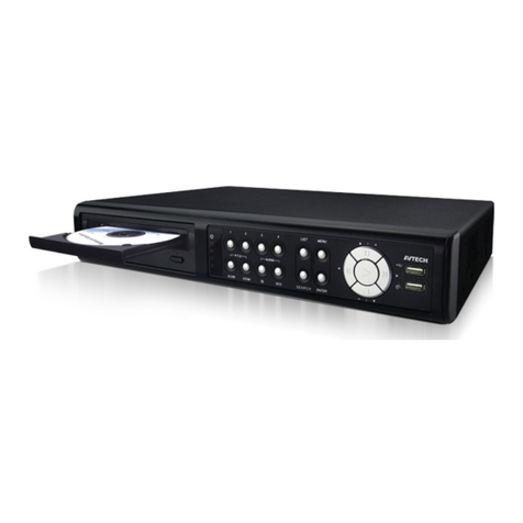
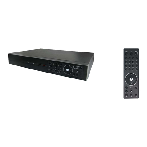
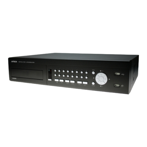
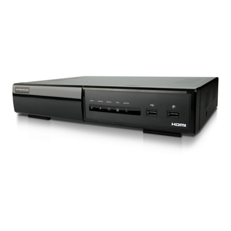
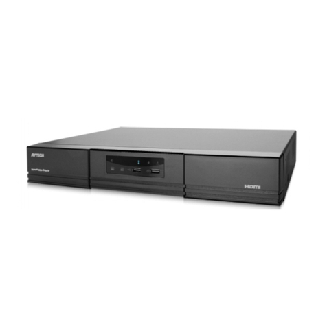
Avtech AVC798 User manual

Multilingual Version
English
中文
Arabic
Italiano
Français
Español
日本語
Deutsch

a793cneu_798b_c_796b_c_Quick_V1.1
H.264 Network DVR
Quick Start
GUI Display with USB Mouse Control
Please read instructions thoroughly before operation and retain it for future reference.
For the actual display & operation, please refer to your DVR in hand.

IMPORTANT SAFEGUARD
CAUTION
RISK OF ELECTRIC SHOCK
CAUTION:
To reduce the risk of electric shock, do not expose this apparatus to rain or moisture. Only operate this apparatus from the type of
power source indicated on the label. The company shall not be liable for any damages arising out of any improper use, even if we
have been advised of the possibility of such damages.
The lightning flash with arrowhead symbol, within an equilateral triangle, is intended to alert the user to the presence of
uninsulated “dangerous voltage” within the product’s enclosure that may be of sufficient magnitude to constitute a risk of
electric shock to persons.
This exclamation point within an equilateral triangle is intended to alert the user to the presence of important operating and
maintenance (servicing) instructions in the literature accompanying the appliance.
All lead-free products offered by the company comply with the requirements of the European law on the Restriction of
Hazardous Substances (RoHS) directive, which means our manufacture processes and products are strictly “lead-free” and
without the hazardous substances cited in the directive.
The crossed-out wheeled bin mark symbolizes that within the European Union the product must be collected separately at
the product end-of-life. This applies to your product and any peripherals marked with this symbol. Do not dispose of these
products as unsorted municipal waste. Contact your local dealer for procedures for recycling this equipment.
This apparatus is manufactured to comply with the radio interference requirements.
Disclaimer
The information in this manual was current when released. We reserve the right to revise or remove any content in this manual at any time. We
do not warrant or assume any legal liability or responsibility for the accuracy, completeness, or usefulness of this manual. For the actual display
& operation, please refer to your DVR in hand. The content of this manual is subject to change without notice.
Grounding
This is a Safety Class 1 Product (provided with a protective earthing ground incorporated in the power cord). The mains plug shall only be
inserted in a socket outlet provided with a protective earth contact. Any interruption of the protective conductor inside or outside of the
instrument is likely to make the instrument dangerous. Intentional interruption is prohibited.
Water & Moisture
Do not expose this product to dripping or splashing and that no objects filled with liquids, such as vases, shall be placed on the product.
MPEG4 Licensing
THIS PRODUCT IS LICENSED UNDER THE MPEG-4 VISUAL PATENT PORTFOLIO LICENSE FOR THE PERSONAL AND
NON-COMMERCIAL USE OF A CONSUMER FOR (i) ENCODING VIDEO IN COMPLIANCE WITH THE MPEG-4 VISUAL STANDARD
(“MPEG-4 VIDEO”) AND/OR (ii) DECODING MPEG-4 VIDEO THAT WAS ENCODED BY A CONSUMER ENGAGED IN A PERSONAL AND
NON-COMMERCIAL ACTIVITY AND/OR WAS OBTAINED FROM A VIDEO PROVIDER LICENSED BY MPEG LA TO PROVIDE MPEG-4
VIDEO. NO LICENSE IS GRANTED OR SHALL BE IMPLIED FOR ANY OTHER USE. ADDITIONAL INFORMATION INCLUDING THAT
RELATING TO PROMOTIONAL INTERNAL AND COMMERCIAL USES AND LICENSING MAY BE OBTAINED FROM MPEG LA, LLC. SEE
HTTP://WWW.MPEGLA.COM.
GPL Licensing
This product contains codes which are developed by Third-Party-Companies and which are subject to the GNU General
Public License (“GPL”) or the GNU Lesser Public License (“LGPL”).
The GPL Code used in this product is released without warranty and is subject to the copyright of the corresponding
author.
Further source codes which are subject to the GPL-licenses are available upon request.
We are pleased to provide our modifications to the Linux Kernel, as well as a few new commands, and some tools to get
you into the code. The codes are provided on the FTP site, and please download them from the following site or you
can refer to your distributor:
http://download.dvrtw.com.tw/GPL/076D_Series/arm-linux-2.6.tar.gz

TABLE OF CONTENTS
1. GUI DISPLAY WITH USB MOUSE CONTROL........................................................................ 1
1.1 Connect USB Mouse .......................................................................................................................................1
1.2 Quick Menu Bar ...............................................................................................................................................1
1.3 Main Menu .......................................................................................................................................................1
Main Menu Structure ......................................................................................................................................2
2. FRONT AND REAR PANELS .................................................................................................. 3
2.1 Front Panel ......................................................................................................................................................3
2.2 Rear Panel.......................................................................................................................................................4
3. BASIC OPERATION................................................................................................................. 5
3.1 Live Page.........................................................................................................................................................5
3.2 Record Icon .....................................................................................................................................................5
3.3 Playback ..........................................................................................................................................................5
Playback Control ............................................................................................................................................6
Event Search ..................................................................................................................................................6
Audio Playback...............................................................................................................................................6
3.4 User Level Switch ............................................................................................................................................6
3.5 VGA Output Resolution Support ......................................................................................................................7
3.6 System Sources Reallocation (For 4CH Models Only)...........................................................................................7
APPENDIX DCCS CAMERA CONNECTION (For Selected Models Only) ............................... 9
A1 Prerequisites ....................................................................................................................................................9
A2 Installing DCCS Camera ..................................................................................................................................9
A3 Connecting DCCS Camera ..............................................................................................................................9
A4 Examining Signal Transmission......................................................................................................................10

1
1. GUI DISPLAY WITH USB MOUSE CONTROL
1.1 Connect USB Mouse
Connect your USB mouse to one of the USB ports on the DVR front panel, and check if there’s a mouse icon ( )
on the screen, indicating the USB mouse is detected properly.
Move your mouse to enter the DVR password with the password keypad. The default administrator password is
0000. The status will be changed from (key lock) to (administrator), and the quick menu bar appears on
the left side of the screen.
Note: There are two user levels for DVR access which can be set in the main menu “SYSTEM”
“TOOLS”. For details, please refer to your user manual.
Password Input Quick Menu: Close
1.2 Quick Menu Bar
Move to the arrow mark to extend the quick menu bar and show the five functions as follows:
Quick Menu: Open
Click to show the channel switch panel and select the channel you want.
For details, please refer to “3.2 Quick Menu Bar” in the user manual.
Click to display the playback control panel, and click to play the latest
recorded video clip, or click to enter the search list.
Switch to the channel you want first, and click to enter the zoom-in
mode. In this mode, click and drag the red frame on the bottom left of the
screen to move to the place you want to see. To exit this mode, click 7.
Click to select the audio channel you want:
In the live mode, only the live audio channels can be selected.
In the playback mode, live and playback audio channels can be selected.
Click to enter the PTZ mode and show the PTZ camera control panel.
Click to show the power off panel to either halt or reboot the system.
1.3 Main Menu
Right-click anywhere on the screen to show the main menu as follows, and right-click again to exit.
Main Menu
QUICK START Click to set the status display, image settings, and date &
time.
DATE SETUP Click to set the date display and daylight saving.
SYSTEM Click to set the system configurations.
EVENT INFORMATION Click to enter the event search menu.
ADVANCED CONFIG* Click to set CAMERA, DETECTION, ALERT,
NETWORK, DISPLAY, RECORD, DEVICES & DCCS.
SCHEDULE SETTING Click to set record timer, detection timer, and alarm timer.
*The available functions may vary depending on the DVR model you have.

2
Main Menu Structure
QUICK START GENERAL CHANNEL TITLE
EVENT STATUS
DATE DISPLAY
DCCS DISPLAY (For Selected Models Only)
MOUSE SENSITIVIT
Y
PRIORITY (For Selected Models Only)
RECORD CONFIG
TIME SETUP DATE
TIME
DATE SETUP
DATE INFO
DISPLAY DATE OF MODE
FORMAT
DAYLIGHT DAYLIGHT SAVING
SYSTEM
TOOLS
LANGUAGE
ADMIN PASSWORD
OPERATOR PASSWORD
UPGRADE
BACKUP CONFIG
RESTORE CONFIG
SYSTEM INFO BAUD RATE
HOST ID
R.E.T.R.
AUTO KEY LOCK
CLEAR HDD
RESET DEFAULT
REMOTE CONTROL ID
SERIAL TYPE
VIDEO FORMAT
VERSION
BACKUP DATA (USB)
BACKUP DATA (DVD) (For Selected Models Only)
BACKUP LOG (USB)
EVENT INFORMATION
QUICK SEARCH
EVENT SEARCH
HDD INFO
EVENT LOG
ADVANCE
D
CONFIG
CAMERA
BRIGHTNESS
CONTRAST
SATURATION
HUE
COV.
REC
CHANNEL TITLE
DETECTION LS
SS
TS
MOTION
ALARM
AREA
ALERT EXT. ALERT
INT. BUZZER
KEY BUZZER
VLOSS BUZZER
MOTION BUZZER
ALARM BUZZER
HDD BUZZER
ALARM DURATION (SEC)
HDD NEARLY FULL (GB)
NETWORK NETWORK
SNTP
FTP
E-MAIL
DDNS
ADVANCED CONFIG DISPLA
Y
DE-INTERLACE
(
For Selected Models Onl
y)
FULL SCREEN DURATION
QUAD SCREEN DURATION (For Selected Models Only)
DWELL SCREEN DURATION (For Selected Models Only)
DISPLAY COVERT
HDD DISPLAY MODE
VIDEO OUTPUT (For Selected Models Only)
ALPHA BLENDING
VGA OUTPUT
RECORD CONFIG
RECORD MANUAL RECORD
EVENT RECORD
TIMER RECORD
EVENT RECORD IPS
TIMER RECORD IPS
PRE-ALARM RECORD
OVE
R
WRITE
EVENT RECORD ALL CH.
KEEP DATA LIMIT (DAYS)
RECORD CONFIG
DEVICES
DCCS
(
For Selected Models Onl
y)
SCHEDULE SETTING
RECORD
DETECTION
ALARM

3
2. FRONT AND REAR PANELS
2.1 Front Panel
1) LED Indicators
HDD is reading or recording.
An alarm is triggered.
Timer recording is on.
Under playback status.
DVR is powered on.
2) (▲) / (▼) / (◄) / (►)
Press ▲/ ▼/ ◄/ ►to move up / down / left / right.
In the playback mode:
Press “” to pause playback.
Press “” to stop playback.
Press ““ to fast forward.
Press ““ to fast rewind.
3) MENU
Press to enter the main menu.
4) ENTER
Press to confirm the setting.
5) LIST (Event List Search)
Press to quickly search the recorded files by event lists: RECORD / MOTION / ALARM / TIME, or select FULL to
show all the event logs.
To quickly search the time you want, select “QUICK SEARCH”. Set the time range you want, and select “Start”
to play the recorded video clip during the specified time.
6) PLAY
Press to playback the latest recorded data.
7) SLOW
In the playback mode, press to show slow playback.
8) ZOOM
Press to enlarge the picture of selected channel in the FRAME or FIELD recording mode.
9) SEQ
Press to display each channel in full screen one by one starting from CH1. When the last channel is displayed, it
will repeat from CH1 again. To exit this mode, press “SEQ” again.
10)
Press to show the 4 channel display mode.
11) CH1 ~ 16 / 1 ~ 8 / 1 ~ 4
Press the channel number buttons to select the channel to display.
12) SEARCH (For Selected Models Only)
Press to enter the time search menu. Set the time range you want, and select “START” to play the recorded
video clip during the specified time.
13) AUDIO (SLOW + ZOOM)
Press “SLOW” + “ZOOM” to select live or playback audio from audio channel 1~4.
Live audio from audio channel 1~4
(indicated in white)
Playback audio from audio channel 1~4
(indicated in yellow)
Audio channel unselected

4
14) P.T.Z. ( + SEQ)
Press “ ” + “SEQ” at the same time to enter / exit the PTZ control mode.
15) USB port
There are two USB ports on the front panel, one for connecting your USB mouse for mouse control, and the
other one for connecting your USB flash drive for video backup.
Note: It’s not allowed to have two USB mice or two USB flash drives connected on the front panel.
For the compatible USB flash drive list, please refer to “APPENDIX 3” in the user manual.
16) (For Selected Models Only)
Press “ ” to open / close the DVD Writer.
2.2 Rear Panel
1) 75Ω/ HI-IMPEDANCE (For Selected Models Only)
When using Loop function, please switch to HI-IMPEDANCE. When you don’t use Loop function, please switch
to 75Ω.
2) VIDEO IN (1 ~ 16 / 1 ~ 8 / 1 ~ 4): Connect to the video connector of a camera.
VIDEO LOOP (1 ~ 16 / 1 ~ 8): Video output connector.
Note: The DVR will automatically detect the video system of the camera, please make sure that the
cameras are properly connected to the DVR and power-supplied before the DVR is turned on.
3) AUDIO IN (1~4)
Connect to the audio connector of a camera if the camera supports audio recording.
Note: To make a video backup with audio, make sure the camera which supports the audio function is
connected to the video-in channel and audio-in channel. For example, the audio data from audio
CH1 will be recorded with the video data from video CH1.
4) AUDIO OUT
Connect to a speaker with 1 mono audio output.
Note: To know how many audio outputs your DVR supports, please refer to its specifications.
5) MONITOR
Connect to a CRT monitor for video output.
6) CALL
Connect to a monitor specific for sequence display.
7) VGA
Connect to a LCD monitor directly.
8) IR
Connect the optional IR receiver extension cable for remote control.
9) EXTERNAL I/O
This port is used to connect external devices (such as speed dome cameras or external alarm, etc).
For detailed I/O port PIN configuration, please refer to “APPENDIX 6” in your user manual.
10) LAN
Connect to Internet by LAN cable.
11) DC 19V
Connect to the supplied adapter.
12) Power Switch
Switch to “\” to turn on the power, and “|” to turn off the power.

5
3. BASIC OPERATION
3.1 Live Page
Icon Function Icon Function Icon Function
Live audio channel (1~4) Playback audio channel (1~4) Audio channel off
Digital zoom on Digital zoom off Timer recording
Network disconnected Internet connected LAN connected
USB mouse connected USB flash drive / device connected No USB device connected
Key lock PTZ mode on HDD overwrite
Administrator Operator Sequence
Motion Recording Alarm
Record mode: Frame Record mode: Field Record mode: CIF
DCCS connection OK
(For Selected Models Only)
DCCS connection failed
(For Selected Models Only)
3.2 Record Icon
1) Manual Recording
By defaults, manual recording is on ( ) when the DVR is powered on and a HDD is installed.
2) Event Recording
When the motion detection or alarm is on, the motion icon ( ) or alarm icon ( ) shows on the screen for any
motion or alarm event.
3) Timer Recording
When timer recording is on, you will see “ ” on the screen.
4) HDD Overwritten
Be defaults, the HDD overwritten function is set to ON, and “ ” will be shown on the screen.
3.3 Playback
Click “ ” on the quick menu bar to display the playback control panel, and click to play the latest recorded
video clip, or click to enter the search list.

6
Note: There must be at least 8192 images of recorded data for playback to work properly. If not, the
device will stop playback. For example, if the IPS is set to 30, the recording time should be at
least 273 seconds (8192 images / 30 IPS) for the playback to work properly.
Note: During playback, the image size of the recording (FRAME, FIELD or CIF) will be shown on the
screen.
Playback Control
Fast Forward Increase the speed for fast forward. Click once to get 4X speed forward and click
twice to get 8X speed, etc., and the maximum speed is 32X.
Fast Rewind Increase the speed for fast rewind. Click once to get 4X speed rewind and click
twice to get 8X speed, etc., and the maximum speed is 32X.
/ Play / Pause Click to play the latest recorded video clip immediately, and click again to pause.
In the pause mode, click once to get one frame forward, and click to get
one frame rewind.
Stop Click to stop the video playback.
Slow Playback Click once to get 1/4X speed playback, and click twice to get 1/8X speed
playback.
/ Previous /
Next Hour
Click to jump to the next / previous time interval in an hour, for example, 11:00 ~
12:00 or 14:00 ~ 15:00, and start playing the earliest event video clip recorded
during this whole hour.
Repeat Click to set point A and point B in a video clip, and the system will play only the
specified range in that clip.
Backup Click to open the backup menu for video backup.
Event Search
Click to quickly search the recorded files by event lists: RECORD / MOTION / ALARM / TIME, or select
FULL to show all the event logs.
To quickly search the time you want, select “QUICK SEARCH”. Set the time range you want, and select
“SUBMIT” to play the recorded video clip during the specified time.
Audio Playback
In the playback mode, click on the quick menu bar as many times as needed to select live or playback
audio from the audio channel 1~4.
Live audio from audio channel 1~4
(indicated in white).
Playback audio from audio channel 1~4
(indicated in yellow).
Audio channel unselected
Note: To make a video backup with audio, make sure the camera which supports the audio function is
connected to the video-in channel and audio-in channel. For example, the audio data from audio
CH1 will be recorded with the video data from video CH1.
3.4 User Level Switch
In the key lock mode ( ), move your USB mouse to display the password input keypad. There are two user
levels for accessing the DVR: Administrator ( ) & Operator ( ).
When the administrator password is entered, will be shown on the status bar of the screen and all
operations are allowed. The default administrator password is 0000.

7
When the operator password is entered, will be shown on the status bar of the screen, and the main menu
is NOT allowed to access. The operator user level needs to be set in the main menu “SYSTEM” “TOOLS”.
To switch between these two user levels, click the current user level icon to switch to the key lock mode, and
move your mouse to show the password input keypad, and enter the password of the user level you want.
3.5 VGA Output Resolution Support
Users are allowed to change the resolution depending on their display monitor.
Right-click to display the main menu, and select “ADVANCED CONFIG” “DISPLAY”.
ADVANCED CONFIG
CAMERA DE-INTERLACE OFF
DETECTION FULL SCREEN DURATION 03
ALERT QUAD SCREEN DURATION (For Selected Models Only) 03
NETWORK DWELL SCREEN DURATION 03
DISPLAY DISPLAY COVERT ON
RECORD HDD DISPLAY MODE HDD SIZE
DEVICES VIDEO OUTPUT (For Selected Models Only) BOTH
ALPHA BLENDING 200
VGA OUTPUT 1024 x 768
VGA DEINTERLACE (For Selected Models Only) ON
COMPOSITE DEINTERLACE (For Selected Models Only) ON
EXIT
Move to “VGA OUTPUT”, and select the VGA resolution you want. There are three options as follows:
1024 x 768 (default)
1280 x 1024
1600 x 1200
Note: For 4CH models, “VGA OUTPUT” appears only when “PRIORITY” is set to “DISPLAY FIRST”. For
details, please refer to “3.6 System Sources Reallocation (For 4CH Models Only)”.
Note: To have the best image quality on your LCD monitor, make sure (1) the selected DVR VGA output
resolution is supported by your monitor, and (2) the VGA output settings on both the LCD
monitor and DVR are consistent.
If the image is not positioned or scaled properly, please go to your monitor’s menu for
adjustment. For details, please refer to the user manual of your LCD monitor.
3.6 System Sources Reallocation (For 4CH Models Only)
Go to “QUICK START” “GENERAL”, and select “PRIORITY” to reallocate the system sources to live display,
and record.
There are three options for this function: RECORD FIRST / DISPLAY FIRST.
QUICK START
GENERAL CHANNEL TITLE ON
TIME SETUP EVENT STATUS ON
DATE DISPLAY ON
DCCS DISPLAY ON
MOUSE SENSITIVITY - ׀׀׀׀׀׀׀׀׀+
PRIORITY (For 4CH Models Only) RECORD FIRST
RECORD CONFIG SETUP
EXIT

8
RECORD FIRST: When this option is selected, Full D1 at real-time record on all channels is available, and the
VGA output resolution is fixed to 1024 x 768.
DISPLAY FIRST: When this option is selected, three VGA output resolutions will be available to choose (1024
x 768 / 1280 x 1024 / 1600 x 1200), but Full D1 real-time recording on all channels will not
be available.

9
APPENDIX DCCS CAMERA CONNECTION
(For Selected Models Only)
Note: This function is available only for DVR models which support DCCS function.
A1 Prerequisites
Make sure your cameras support the DCCS function. For details, please check with your distributor or
installer.
To ensure the signal transmission, the recommended distance between this DVR and cameras should not
exceed 200 meters by using 3C2V coaxial cables (112 braids).
However, different materials used in 3C2V coaxial cables with different connection distance may cause
some effects for the availability and fluency of signal transmission.
Therefore, please do the DCCS test as instructed in “A4 Examining Signal Transmission” at page 10 when
the connection is completed to ensure this system can work normally.
It’s not allowed to use a signal booster or modem to amplify signals and extend the connection distance.
The DCCS function doesn’t support the channel which is looped from a DCCS camera connected to the
same DCCS DVR or to other DCCS DVR.
A2 Installing DCCS Camera
Install the camera on the wall or ceiling based on your installation environment and camera type. For installation
details, please refer to the user manual of your camera.
Note: The distance between the camera and DVR needs to be within 200 meters for DCCS control to
take effects. For details, please refer to “A1 Prerequisites” at page 9.
A3 Connecting DCCS Camera
The cameras must be connected and power-supplied before the DVR is powered on. Connect the camera with
the indicated power supply. Then, connect the camera video output to the DVR video input port with a coaxial
cable or RCA cable with BNC connectors.
Note: Only video channel 1 supports DCCS camera connection.
1) Video cable connection
Connect the camera video output to the DVR video input port with a coaxial cable or RCA cable with BNC
connector.
2) Power connection
Connect the camera with indicated power supply and make sure it’s power-supplied.

10
A4 Examining Signal Transmission
When the DVR is powered on, right-click to display the main menu, and select “ADVANCED CONFIG”
“DCCS”.
ADVANCED CONFIG
C A N E R A CH1 CH2 CH3
CH4
CH5
CH6
CH7
CH8
CH9
CH10
CH11 WX
DETECTION
DIAGNOSTIC START
ALERT
MENU SETUP
NETWORK
DISPLAY
RECORD
DEVICES
DCCS DEVICE AVK523
IVS
CONNECTION OK
NOTIFY
EXIT
1) Make sure the model number of your DCCS camera is shown in “DEVICE”. If not, please check your camera
connection.
2) Select the channel which connects to your DCCS camera, and click “START” in “DIAGNOSTIC” to examine
the signal transmission between the DCCS camera and the DVR.

433Z
中文_a793cneu_798b_796b_Quick_V1.0
H.264 數位錄放影機
快速使用指南
支援圖形化介面與 USB 滑鼠控制
在使用本機前請務必詳細閱讀安全須知及操作說明,並保存此手冊以備後續參考。
產品畫面顯示與操作請以實機為主。

433Z
安全須知
注意
RISK OF ELECTRIC SHOCK
注意:
為減低觸電的可能性,請勿讓此機器暴露在雨中或潮濕的環境下。請務必使用適當的變壓器。本公司不負責賠償任何因不當使用本產
品所引起的損害。即使本公司已被告知可能的相關風險,使用者仍應自行承擔不當使用所產生之後果。
此符號用於警告使用者 產品機殼內部有 “危險電壓”,觸碰有可能會造成觸電的可能性。
此符號用於告知使用者此機器附有操作與維護指示的重要文件。
本公提供的所有無鉛產品皆符合歐盟有害物質使用限制指引 (Restriction of Hazardous Substances, (RoHS)),意即本公司的
生產流程與產品均嚴格遵守無鉛守則,而且不包含該指引內提供的任何有害物質。
此劃叉的滾輪垃圾筒圖示代表在歐盟境內,本產品於丟棄時必須另行收集。此原則適用於您的產品與任何標有此圖示的週邊
設備。請勿隨意丟棄這些產品。請洽詢您當地的經銷商,以得知回收此設備的程序。
此機器的製造符合無線電波干擾的規範。
商標聲明
iPhone® 是Apple Inc 的註冊商標。BlackBerry® 與其相關商標、名稱和標示皆為 Research In Motion Limited 的財產,並由 Research In Motion
Limited 授權於 U.S. 和其他國家註冊使用。此文件提及的 Microsoft®、Windows®、Internet Explorer®、Mozilla® Firefox®、Google Chrome™、
QuickTime®、Windows® Mobile & Symbian® 皆為其各自擁有者的註冊商標。
接地
此為符合 Safety Class 1 Product (隨附的電源插頭有內建接地線) 的產品,其主電源插頭應插入支援接地線的三孔電源插座。任何破壞接地保護
的舉動都可能會使得本產品具有危險性。因此,請勿刻意破壞接地保護。
遠離有水或潮溼的環境
請勿讓本產品曝露在任何有水或潮溼的環境下,例如將水瓶放在本產品上,或者容易滴到雨水的窗戶邊。
MPEG4
授權
THIS PRODUCT IS LICENSED UNDER THE MPEG-4 VISUAL PATENT PORTFOLIO LICENSE FOR THE PERSONAL AND
NON-COMMERCIAL USE OF A CONSUMER FOR (i) ENCODING VIDEO IN COMPLIANCE WITH THE MPEG-4 VISUAL STANDARD
(“MPEG-4 VIDEO”) AND/OR (ii) DECODING MPEG-4 VIDEO THAT WAS ENCODED BY A CONSUMER ENGAGED IN A PERSONAL AND
NON-COMMERCIAL ACTIVITY AND/OR WAS OBTAINED FROM A VIDEO PROVIDER LICENSED BY MPEG LA TO PROVIDE MPEG-4
VIDEO. NO LICENSE IS GRANTED OR SHALL BE IMPLIED FOR ANY OTHER USE. ADDITIONAL INFORMATION INCLUDING THAT
RELATING TO PROMOTIONAL INTERNAL AND COMMERCIAL USES AND LICENSING MAY BE OBTAINED FROM MPEG LA, LLC. SEE
HTTP://WWW.MPEGLA.COM.
GPL
授權
This product contains codes which are developed by Third-Party-Companies and which are subject to the GNU General
Public License (“GPL”) or the GNU Lesser Public License (“LGPL”).
The GPL Code used in this product is released without warranty and is subject to the copyright of the corresponding
author.
Further source codes which are subject to the GPL-licenses are available upon request.
We are pleased to provide our modifications to the Linux Kernel, as well as a few new commands, and some tools to get
you into the code. The codes are provided on the FTP site, and please download them from the following site or you
can refer to your distributor:
http://download.dvrtw.com.tw/GPL/076D_Series/arm-linux-2.6.tar.gz
目錄
1. 圖形化介面與 USB 滑鼠控制簡介 ............................................................................................ 1
1.1 連接 USB 滑鼠 .................................................................................................................................................1
1.2 快速選單列.......................................................................................................................................................1
1.3 主目錄選單.......................................................................................................................................................1
主目錄選單架構 ..............................................................................................................................................2
2. 前面板與背板 ........................................................................................................................... 4
2.1 前面板..............................................................................................................................................................4
2.2 背板..................................................................................................................................................................5
3. 基本操作................................................................................................................................... 6
3.1 即時畫面 ..........................................................................................................................................................6
3.2 錄影圖示 ..........................................................................................................................................................6
3.3 影像回放 ..........................................................................................................................................................6
回放操作.........................................................................................................................................................7
事件搜尋.........................................................................................................................................................7
錄音回放.........................................................................................................................................................7
3.4 切換使用權限 ...................................................................................................................................................7
3.5 VGA 輸出支援解析度.......................................................................................................................................7
3.6 系統資源重新配置 (
僅限四路的機種
)....................................................................................................................8
附錄 DCCS 攝影機連接 (
僅限
4CH
型號
)............................................................................................ 9
A1 必要條件:.......................................................................................................................................................9
A2 架設 DCCS 攝影機...........................................................................................................................................9
A3 DCCS 攝影機連線 ............................................................................................................................................9
A4 傳輸訊號檢驗....................................................................................................................................................9

1
1. 圖形化介面與 USB 滑鼠控制簡介
1.1 連接 USB 滑鼠
將USB 滑鼠插入 DVR 前面板的 USB 埠,然後等到螢幕出現滑鼠圖示 ( ),表示已正確偵測到 USB 滑鼠。
移動滑鼠即會出現密碼輸入視窗,要求你輸入 DVR 密碼。預設的管理者密碼為 0000。輸入後,DVR 狀態會從
(上鎖) 變成 (管理者),螢幕左側會出現快速選單列。
註:DVR 支援兩種使用者權限,使用者可以在主目錄選單的系統資訊 工具裡進行設定。詳情請參閱使用說明書。
密碼輸入 快速選單列:收合
1.2 快速選單列
將滑鼠移到箭號即可展開快速選單列,顯示以下五種功能:
快速選單列:展開
顯示頻道切換面板,讓使用者選擇想要切換的頻道。詳情請參閱使用說明
書的「3.2 快速選單列」。
顯示回放操作面板。按 回放最新一筆的錄影資料,或按 進入搜尋
事件清單。
先切換到想要的頻道,然後再按 放大影像。在放大模式下,按住並拖
曳螢幕左下角的紅框可移到想要查看的位置。若要退出此模式,請按 。
選取想要的聲音頻道。
在即時畫面下,只能選擇收聽即時聲音。
在回放模式下,可以選擇收聽即時聲音或錄音。
進入 PTZ 模式並顯示 PTZ 攝影機控制面板。
顯示關機畫面,選擇要關機或重新啟動系統。
1.3 主目錄選單
在螢幕任一處按右鍵即可顯示主目錄選單,再按一下即可退出。
主目錄選單
快速設定 設定狀態顯示、影像設定,以及日期和時間。
日期設定 設定日期顯示和日光節約時間。
系統資訊 設定系統相關配置。
事件資訊 進入事件搜尋選單。
進階選單 進入攝影機設定、偵測設定、警示音設定、網路設定、網路對時設定、
顯示設定、錄影設定和外接裝置設定目錄。
預約設定 設定預約錄影、預約偵測錄影、或預約警報錄影。

2
主目錄選單架構
快速設定
一般設定
頻道名稱
事件狀態
顯示日期
DCCS 顯示 (
僅限特定型號
)
滑鼠靈敏度
優先順序 (
僅限特定型號
)
錄影設定
時間設定
日期
時間
日期設定
日期資訊
日
期顯示模式
格式
日光節約
日光節約時間
系統資訊
工具
多國語言
管理者密碼
操作者密碼
升級
備份設定檔
還原設定檔
系統資訊
鮑率
主機 ID
R.E.T.R.
按鍵鎖 (秒)
清除硬碟
回復預設值
遙控 ID
序列裝置類別
影像格式
版本
錄影備份 (USB)
錄影備份 (光碟) (
僅限特定型號
)
事件清單備份 (USB)
事件資
訊
快速搜尋
事件搜尋
硬碟資訊
事件記錄
進階選單
攝影機設定
亮度
對比
飽合
色相
隱蔽
錄影
頻道名稱
偵測設定
LS
SS
TS
偵測設定
警報
移動區域設定
警示音設定
外部警示音設定
內部警示音
按鍵音
影像遺失警示音
位移偵測警示音
警報警示音
硬碟警示音
警示音時間 (秒)
硬碟空間不足 (GB)
網路設定
網路設定
網路對時設定
FTP
電子郵件
DDNS
進階選單 顯示設定 去交錯 (僅限特定型號)
全螢幕跳台停留時間 (秒)
四分割跳台停留時間 (秒) (僅限特定型號)
跳台停留時間 (秒)
顯示隱蔽字樣
剩餘硬碟空間顯示方式
影像輸出 (僅限特定型號)
視窗透明度
VGA 輸出
錄影設定
錄影設定 手動錄影
事件錄影
預約錄影
事件錄影 (IPS)
預約錄影 (IPS)
警報前錄影
硬碟覆寫
事件觸發後全頻道錄影
保留資料天數
錄影設定
外接裝置設定
DCCS
(
僅限特定型號
)

3
預約設定
錄影設定
偵測設定
警報設定
Other manuals for AVC798
2
Table of contents
Other Avtech DVR manuals

Avtech
Avtech CPD560 User manual

Avtech
Avtech KPD674 User manual

Avtech
Avtech AVC792 User manual

Avtech
Avtech 715ZC User manual

Avtech
Avtech avh-312 User manual

Avtech
Avtech AVC796 User manual

Avtech
Avtech AVH304 User manual

Avtech
Avtech MPEG4 User manual

Avtech
Avtech AVD 714 User manual

Avtech
Avtech DG10 Series User manual

Avtech
Avtech AVH364 User manual

Avtech
Avtech AVC791A User manual

Avtech
Avtech KPD Series User manual

Avtech
Avtech AVH306 User manual

Avtech
Avtech AVC798 User manual

Avtech
Avtech DGD8132 User manual

Avtech
Avtech AVC799B User manual

Avtech
Avtech AVH306 User manual

Avtech
Avtech MDR688ZB User manual

Avtech
Avtech AVC 760 Setup guide