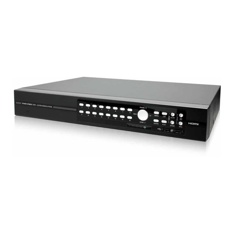
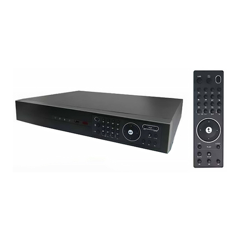
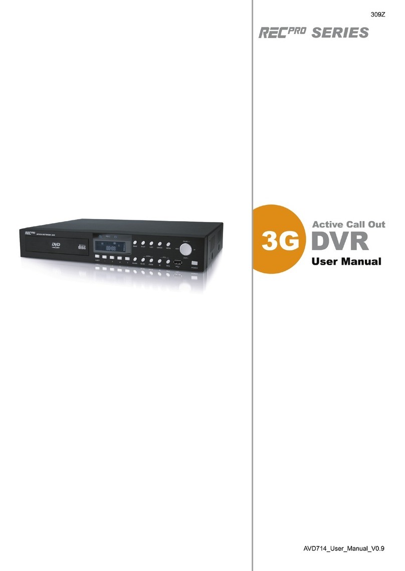
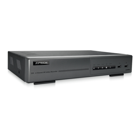
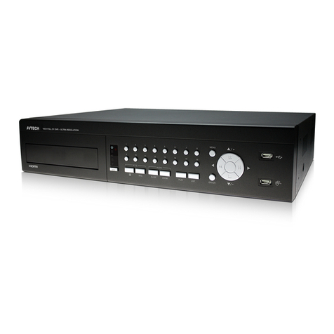
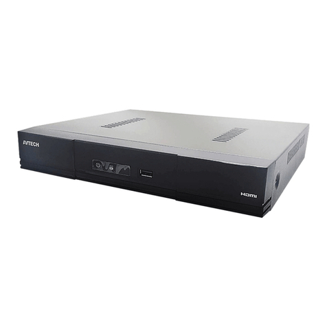
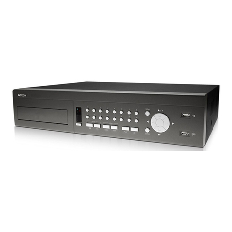
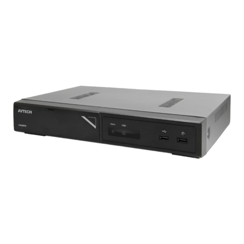
Avtech AVD715ZC User manual

208Z
715ZC, 717ZC / 715ZD, 717ZD_QUICK / 715Z, 717Z_V1.7
HIGH-END SERIES
All lead-free produc s offered by he company comply wi h he requiremen s of he European law on
he Res ric ion of Hazardous Subs ances (RoHS) direc ive, which means our manufac ure processes
and produc s are s ric ly “lead-free” and wi hou he hazardous subs ances ci ed in he direc ive.
The crossed-ou wheeled bin mark symbolizes ha wi hin he European Union he produc mus be
collec ed separa ely a he produc end-of-life. This applies o your produc and any peripherals
marked wi h his symbol. Do no dispose of hese produc s as unsor ed municipal was e.
ROHS AND WEEE COMPLIANCE

QUICK INSTALLATION
Page 1
1. OVERVIEW
1.1 Product Description
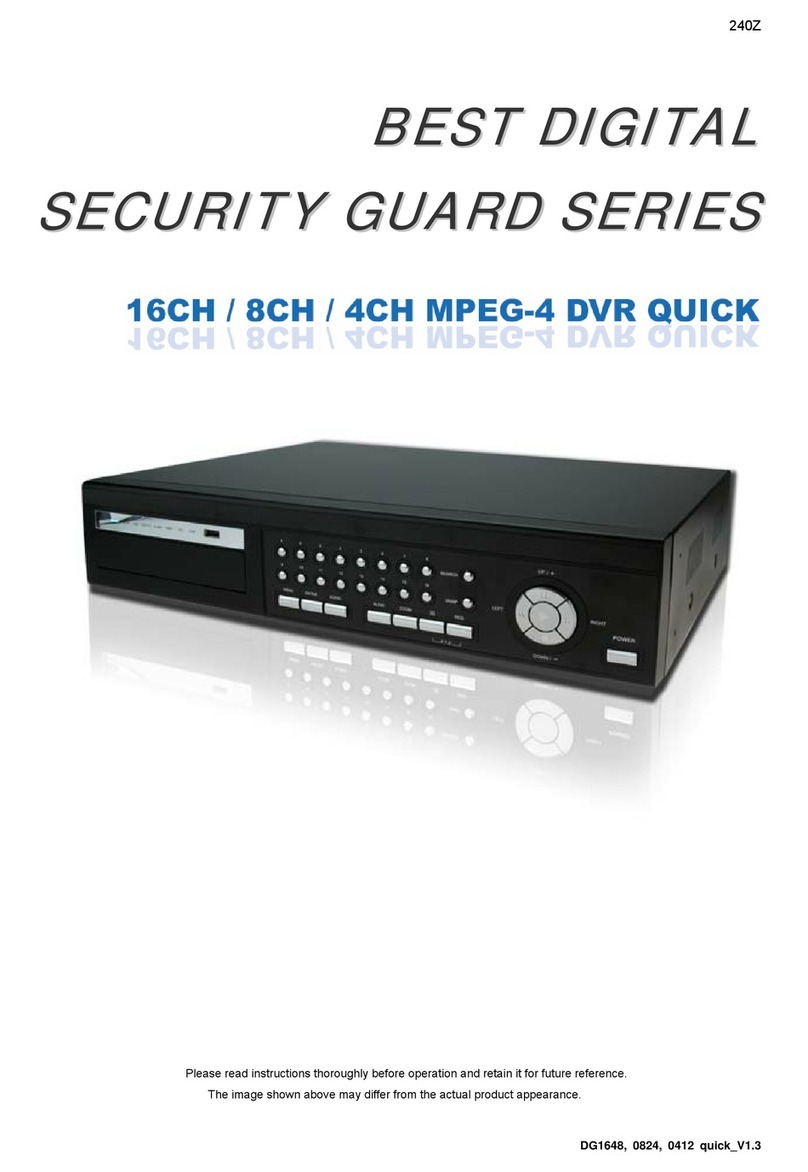
Wi h he high s orage capaci y fea ure, his MPEG-4 DVR model is designed o accommoda e up o 3 HDDs, or
accommoda e 2 HDDs and connec 1 independen disk array depending on your needs. To quickly backup, a CD or DVD
wri er (op ional) and USB in erface are buil in for your choices excep for ne work backup. Remo e Even Trigger
Recording (R.E.T.R.) can be ac iva ed remo ely and any even recording will be saved in he specified pa h in your PC. An
IR ransmi er is also supplied for remo e con rol.
1.2 Package Contents
ITEMS QTY
Digi al Video Recorder (DVR) 1
Adap er and Power Cord 1
Screws 12
DSUB PIN Connec or 1
HDD Da a BUS Clip 1
IR Transmi er and IR Receiver Line (1.5m) 1
Manual 1
Quick Guide 1
CD or DVD disk (op ional) 1
Licensed Sof ware AP 1
2. REAR PANELS
‧ 8CH
DC 19V
INPUT
DISK ARRAY
LOOP
RS 485
INPUT
IR
INPUT INPUT
EXTERNAL I/O
USB
INPUT
LOOP
3
LOOP LOOP LOOP
INPUT
D / V LAN
INPUT
ACT.
LINK
INPUT
CALL
LOOP LOOP LOOP
MONITOR
31
2 4
‧ 16CH
D / V
DISK ARRAY IR
RS 485
EXTERNAL I/O
USB
LAN
LINK
ACT.
DC 19V
MONITOR
CALL
LOOP
INPUT
1 2 3 4 5 6 7 8 9 10 11 12 13 14 15 16
HI-IMPEDANCE
1 875Ω
HI-IMPEDANCE
916
75Ω

QUICK INSTALLATION
Page 2
3. SETUP AND CONNECTIONS
3.1 Insta HDD
Carefully follow he s eps below o ensure correc HDD ins alla ion.
Note: The PCB side of the HDD must face upward, shown as the picture below.
S ep 1: Loosen he screws on he upper cover and open he upper cover of he DVR
S ep 2: Screw ou he HDD bracke .
S ep 3: Get suitable brand HDD and set the HDD mode (Master / lave) according to the indication.
S ep 4: After HDD mode setup, screw all he HDDs on o he HDD bracke s, and replace he HDD bracke s back o he
indica ed posi ion of he DVR base (Be sure to fo ow the indicated position shown as the picture be ow).
Note: For HDD mode setting rule and position, please refer to the following instructions:
* If you plan to install three HDDs, please set two HDDs to Master mode, and one HDD to lave mode,
and place them to the exact position according to the indication.
* If you plan to install two HDDs, please set one HDD to Master mode and place it to the Master 1 position,
and set the other HDD to lave mode and place it to the lave 1 position.
* If you plan to install only one HDD, please set the HDD to Master mode and place it to the Master 1 position.
S ep 5: Depending on which HDD you wan o ins all, connec he HDD o he indica ed power connector and IDE BUS
(make sure o align he HDD precisely for pin connec ion). For de ailed connec ion, please follow and see he
illus ra ion below:
NOTE: If you plan to install external disk array, please don’t install the HDD in the “HDD3”postion.
S ep 6: Close he upper cover of he DVR, and fas en all he screws you loosened in S ep 1.

QUICK INSTALLATION
Page 3
3.2 Camera Connection
The cameras mus be connec ed and power-supplied before he DVR is urned on. For de ailed DVR video inpu /
ou pu por s, please refer o sec ion “2. REAR PANELS” a page 1. For de ailed ex ernal I/O por descrip ion, please refer
o he sec ion “5. PIN CONFIGURATION” a page 13. For de ailed camera se up, please refer o i s own manual.
3.2.1 Norma Camera Connection
1) Connec he camera wi h indica ed power supply.
2) Connec he camera video ou pu signal o DVR video inpu por wi h coaxial cables or RCA line wi h BNC connec or.
For de ailed camera i le, ID, pro ocol and baud ra e se up, please refer o sec ion “6.4.5 Remo e” a page 32 of he
manual.
3.2.2 PTZ Camera Connection
1) Connec he PTZ camera wi h indica ed power supply.
2) Connec he PTZ camera video ou pu o he DVR video inpu por wi h a coaxial cable or RCA line wi h BNC
connec or.
3) Connec “RS485-A” line (brown color) o RS485-A por on he rear panel of he DVR. Connec “RS485-B” line (orange
color) o RS485-B por on he rear panel of he DVR.
NOTE: For detailed camera ID, protocol and baud rate setup at DV side, please refer to section “6.4.5 Remote” at page 32
of the manual.
For detailed camera ID, protocol and baud rate setup at remote AP software side, please refer to section “(1)
Device” at page 55 of the manual (AP software system configuration). For detailed PTZ setup and control instructions,
please refer to section “6.6.5 PTZ Camera etup and Control” at page 42 of the manual.

QUICK INSTALLATION
Page 4
3.3 Externa Device Connections (Optiona )
3.3.1 VGA Converter
This op ional peripheral (VGA Conver er) allows your DVR o have VGA ou pu func ion. For he connec ion me hod,
please refer o he following figure:
3.3.2 Independent Disk Array
For he connec ed IDA o be correc ly de ec ed by your DVR, please don’ ins all HDD in he “HDD3” posi ion (For
connec ion de ails, please refer o "3.1 Ins all HDD" a page 2).
1) Ins all HDDs:
Ins all HDDs in he IDA. Please se he HDD as “Mas er” mode (do no use “Slave” mode). Af er all HDDs are ins alled,
please lock he HDD ray by using he HDD key supplied in he IDA package.
2) Connec all IDA wi h SCSI cable (IDE in erface):
Connec from one of he hree “DEVICE PORT” a one IDA rear panel o he hos por of ano her disk array.
One IDA (as he mas er layer) can connec up o 3 IDA as he second layer, and each IDA in he second layer can
respec ively connec up o 3 IDA as he hird layer. Please refer o he illus ra ion below for de ails.
Note: In order to accurately detect all the connected disk arrays, please make sure to turn on the power of
all the disk arrays after the connection is completed. The maximum layer number is 3, totally 13 IDA.
3) Connec he mas er IDA o your DVR wi h a SCSI Cable (IDE in erface):
Connec he hos por of he mas er IDA o he “DISK ARRAY” por of your DVR. Please refer o he illus ra ion below.

QUICK INSTALLATION
Page 5
3.4 Power Setup
This device should be opera ed only wi h he ype of power source indica ed on he manufac urer’s label. Connec he
indica ed AC power cord o he power adap er, and plug in o an elec rical ou le . “POWER” LED will be on as red. Press
“POWER” bu on, and “POWER” LED will be on as green. I akes approxima ely 10 o 15 seconds o boo he sys em.
3.5 Date and Time Setting
Before any opera ion of he DVR, please se he da e and ime on your DVR firs .
You can use he following bu ons for menu se ing:
BUTTON FUNCTION
UP, DOWN, LEFT, RIGHT Move he cursor.
+ , - Choose numbers / selec ions.
ENTER Go o he submenu / confirm he selec ion.
MENU Go o he menu lis / confirm he change / exi he menu lis .
1) Da e and Sys em:
DATE
DATE 2006-AUG-28 18:30:00
FORMAT Y-M-D
DAYLIGHT SAVING ON
2) Dayligh Saving:
The menu pa h is as following: “MENU” → “DATE” → “DAYLIGHT SAVING”.
DAYLIGHT SAVING
START 4
TH
-SUN-MAR 24:00:00
END 4
TH
-SUN-OCT 24:00:00
ADJUST 01:00
Note: Please DO NOT change the date or time of your DVR after the recording function is activated.
Otherwise, the recorded data will be disordered and you will not be able to find the recorded file to
backup by time search. If users change the date or time accidentally when the recording function is
activated, it’s recommended to clear all HDD data, and start recording again.
Note: If the time and date settings return to their default values after the DVR is rebooted, please charge the
DVR for at least 24-48 straight hours. Please contact your local retailer if the situation still occurs.
3.6 LAN or Internet Setup
3.6.1 STATIC IP
1) Build a Local Area Ne work (LAN) be ween DVR and PC/NB wi h ne work cable:
Your NB/PC and DVR mus be under he same ne work domain o build he area ne work. Please change he IP
address of your PC/NB in o 192.168.1.X (X can be he number be ween 1~255, excep 10) and he subne mask in o
255.255.255.0 for communica e wi h he DVR.

QUICK INSTALLATION
Page 6
Ins all he supplied AP sof ware on your NB/PC. Then, log in o he DVR wi h he supplied AP sof ware for he following
defaul DVR se ings.
‧ The DVR defaul IP address: 192.168.1.10
‧ The DVR defaul accoun / password: admin
‧ The DVR defaul por : 80
2) Se DVR ne work se ing in “SYSTEM CONFIG” → “Ne work” of he supplied AP:
In “SYSTEM CONFIG” → “Ne work” of he supplied AP, selec he “Static IP” in “IP TYPE” sec ion. And hen ype he
“Server IP”, “Gateway”, “Net Mask” and “Web Port” (1~9999) informa ion ob ained from your ISP. Press ”APPLY” bu on
o confirm he se ing.
3) Login your DVR via an E herne or dial-up ne work:
Af er se ing up he ne work informa ion of he DVR and connec i o he ne work, you can use he IP address / Por /
Accoun / Password you jus en ered in he supplied AP sof ware o log in o your DVR remo ely.
Note: Before changing the network properties of your PC/NB, please write down the original network
properties in case you need to recover the properties later.
3.6.2 DDNS App y
You need o apply a DDNS accoun before se ing PPPoE or DHCP connec ion. DDNS is a service for ransforming
he dynamic IP corresponding o a specific “Hos name”. For DDNS se up, please refer o he s eps below.
‧ Go o a websi e which provides free DDNS services and apply a “Hos name”.
For example, go o h p://www.dyndns.com.
‧ En er all he informa ion necessary for signing up an accoun according o he websi e ins ruc ions.

QUICK INSTALLATION
Page 7
‧ Then, you will see he screen “Accoun Crea ed”, and Dyndns will email he ins ruc ions o your specified E-mail
address for enabling your accoun . You mus comple e he procedure according o he ins ruc ions in he mail. Tha is
o mus visi he confirma ion address wi hin 48 hours of he ime ha he e-mail was sen o comple e he accoun
crea ion process. Then, you will see “Accoun Confirmed”. Your accoun is crea ed successfully now.
‧ Log in wi h your accoun informa ion and click ”My Service”.

QUICK INSTALLATION
Page 8
‧ Click ”Add Hos Services”.
‧ Click ”Add Dynamic DNS Hos ”.
‧ Fill in and choose he desired hos name.

QUICK INSTALLATION
Page 9
‧ The hos name is crea ed. You will be connec ed o he corresponding IP address whenever you en er his hos name.
3.6.3 Dynamic IP -
--
- PPPOE
1) Build a Local Area Ne work (LAN) be ween DVR and PC/NB wi h ne work cable:
Your NB/PC and DVR mus be under he same ne work domain o build he area ne work. Please change he IP
address of your PC/NB in o 192.168.1.X (X can be he number be ween 1~255, excep 10) and he subne mask in o
255.255.255.0 for communica e wi h he DVR.
Ins all he supplied AP sof ware on your NB/PC. And hen login he DVR wi h he supplied AP sof ware for he
following defaul DVR se ings.
‧ The DVR defaul IP address: 192.168.1.10
‧ The DVR defaul accoun / password: admin
‧ The DVR defaul por : 80
2) Se DVR ne work se ing in “SYSTEM CONFIG” → “Ne work” of he supplied AP:
In he “SYSTEM CONFIG” → “Ne work” of he supplied AP, selec he “PPPOE” in “IP TYPE” sec ion. And hen ype
he “User Name” and “Password” ob ained from your ISP. Press ”APPLY” bu on o confirm he se ing.
3) Se DVR DDNS se ing in he “SYSTEM CONFIG” → “Ne work” → “DDNS” of he supplied AP sof ware.
‧ DDNS: Choose “Enable”.
‧ User Name: Type your DDNS account.
‧ Password: Type your DDNS password.
‧ Domain: Type he “Host Name” you applied previously (EX: securi yany ime.dyndns.org).
‧ Sys em Name: Choose he DDNS server where you applied he domain name (EX: dyndns).
Af er se ing, please press “APPLY” bu on o confirm and finish he se ing.

QUICK INSTALLATION
Page 10
4) Login your DVR via an E herne or dial-up ne work.:
Af er se up he ne work informa ion of he DVR, you can ype DDNS hos name and defaul user name and password
in he supplied AP sof ware login page o log in o your DVR remo ely.
3.6.4 Dynamic IP -
--
- DHCP
Ge a rou er and use he defaul IP address provided by your rou er o login o he rou er. Enable he DHCP server
and se he s ar ing IP address, ending IP address and lease ime. The DHCP Server of he rou er will au oma ically
alloca e an unused IP address from he IP address pool o he reques ing compu er.
1) Build a Local Area Ne work (LAN) be ween DVR and PC/NB wi h ne work cable:
Your NB/PC and DVR mus be under he same ne work domain o build he area ne work. Please change he IP
address of your PC/NB in o 192.168.1.X (X can be he number be ween 1~255, excep 10) and he subne mask in o
255.255.255.0 for communica e wi h he DVR.
Ins all he supplied AP sof ware on your NB/PC. And hen login he DVR wi h he supplied AP sof ware for he
following defaul DVR se ings.
‧ The DVR defaul IP address: 192.168.1.10
‧ The DVR defaul accoun / password: admin
‧ The DVR defaul por : 80
2) Se DVR ne work se ing in “SYSTEM CONFIG” → “Ne work” of he supplied AP:
In he “SYSTEM CONFIG” → “Ne work” of he supplied AP, selec he “DHCP” in “IP TYPE” sec ion. Then
press ”APPLY” bu on o confirm he se ing.
Se DVR DDNS se ing in he “SYSTEM CONFIG” → “Ne work” → “DDNS” of he supplied AP sof ware.
‧ DDNS: Choose “Enable”.
‧ User Name: Type your DDNS account.
‧ Password: Type your DDNS password.
‧ Domain: Type he “Host Name” you applied previously (EX: securi yany ime.dyndns.org).
‧ Sys em Name: Choose he DDNS server where you applied he domain name (EX: dyndns).

QUICK INSTALLATION
Page 11
3) Af er se ing, please press “APPLY” bu on o confirm and finish he se ing.
4) Login your DVR via an E herne or dial-up ne work:
Af er se up he ne work informa ion of he DVR, you can ype DDNS hos name and defaul user name and
password in he supplied AP sof ware login page o log in o your DVR remo ely.
3.7 Password and User Name Setting
3.7.1 DVR Password Setting
You can use he following bu ons for menu se ing:
BUTTON FUNCTION
UP, DOWN, LEFT, RIGHT Move he cursor.
+ , - Choose numbers / selec ions.
ENTER Go o he submenu / confirm he selec ion.
MENU Go o he menu lis / confirm he change / exi he menu lis .
1) Admin password:
Password for supervisor, allow all he se up of DVR.
2) Gues password:
Only allow viewing he live s reaming video and sequencing display, shif ing he channel display, and locking keys.
Note: The menu path is as following: MENU → ADVANCE → Y TEM → PA WORD → ETUP → ADMIN
PA WORD / GUE T PA WORD.
3.7.2 Remote Login Password and User Name Setting
In he “SYSTEM CONFIG” → “General” → “Accoun ” of he supplied AP, you can se up he user’s accoun (Max 5
accoun s), password, life ime, and au hori y level (Max 5 users on line a he same ime) for remo e login o he DVR. For
de ailed ins ruc ions, please refer o “(1) Accoun ” in he sec ion “7.5.4 General” a page 64 of he manual.

QUICK INSTALLATION
Page 12
4. RECORDING
This device offers hree recording modes: manual record, even record and imer record. If he power is off
acciden ally, he recorded video da a will no be los and is safely s ored in he HDD. The device will re urn o he original
recording s a us af er he power is on again.
‧ MANUAL RECORD (con inuous recording)
Recording is ini ia ed by manually pressing “REC” bu on on he fron panel.
This mode is indica ed by he sign “” on he screen.
‧ EVENT RECORD ( riggered by mo ion and ex ernal alarm)
When his func ion is ac iva ed, he recording is riggered by mo ion or ex ernal alarms.
This mode is indica ed by he sign " " (mo ion) or " " (ex ernal alarm) on he screen.
‧ TIMER RECORD (scheduled ime)
Recording is scheduled by TIMER func ion.
This mode is indica ed by he wording “TIMER RECORD”.
When he recording func ion is ac iva ed, please DO NOT change he da e or ime on your DVR. The recorded da a
will be disordered and you will no be able o find he recorded da a o backup by ime search.
Note: If users change the date or time accidentally when the recording function is activated, it’s
recommended to clear all HDD data, and start recording again.
Overwriting Mode
If he overwri ing mode is enabled, you will see “-OW-” (1) under he recording mode excep he sys em ime (2),
available HDD capaci y (3), recording icon (4) and channel i le (5).
When he HDD is full under “-OW-” recording mode, he previous recorded da a will be overwri en wi hou no ice.
Under “-OW-" mode, his device will clear 8GB da a from he oldes for con inuous recording once he HDD is full.
To urn on/off his mode, please refer o he sec ion “6.4.6 Sys em” a page 33.

Page 13
5. PIN CONFIGURATION
When he magne ic con ac is opened, he alarm will be riggered and he recording is on. A he same ime, COM
connec s wi h NO and he siren wi h s robe s ar s wailing and flashing.
NOTE: Please go to MENU -> ADVANCE -> DETECTION -> DETECTION ETUP, and set ALARM to LOW on the
local machine.
PIN FUNCTION DESCRIPTION
1 GND GROUND
2~9 ALARM INPUT When connec ing he wire from ALARM INPUT (PIN 2 --
9) o GND (PIN 1) connec or, DVR
will s ar recording and he buzzer will be on.
10 PIN OFF
11 TXD232 Using RS-232 serial communica ion signals, DVR can be con rolled remo ely b
y he
keyboard of PC
12 RS485-A Using RS-
485 serial communica ion signals, DVR can be con rolled remo ely by he
keyboard of PC
13 EXTERNAL
ALARM NO.
Under he normal opera ion, COM disconnec s wi h NO. Bu when any alarm is riggered,
COM connec s wi h NO.
A en ion: The vol age res ric ion is under DC24V 1A.
14 PIN OFF
15~22
ALARM INPUT When connec ing he wire from ALARM INPUT (PIN 15 --
22) o GND (PIN 1) connec or,
DVR will s ar recording and he buzzer will be on.
23 RXD232 Using RS-232 seria
l communica ion signals, DVR can be con rolled remo ely by he
keyboard of PC
24 RS485-B Using RS-
485 serial communica ion signals, DVR can be con rolled remo ely by he
keyboard of PC
25 EXTERNAL
ALARM COM
Under he normal opera ion, COM disconnec s wi
h NO. Bu when any alarm is riggered,
COM connec s wi h NO.
A en ion: The vol age res ric ion is under DC24V 1A.

Page 14
6. ENU TREE
This manual suits for next models
5
Table of contents
Other Avtech DVR manuals

Avtech
Avtech AVC796 User manual

Avtech
Avtech 616 User manual

Avtech
Avtech AVH504P User manual

Avtech
Avtech DGD1017A User manual

Avtech
Avtech AVC799B User manual

Avtech
Avtech CPD560 User manual

Avtech
Avtech AVC798 User manual

Avtech
Avtech KPD Series User manual

Avtech
Avtech AVD 714 User manual

Avtech
Avtech KPD616 User manual

Avtech
Avtech AVC708H User manual

Avtech
Avtech IC-AVH1109 User manual

Avtech
Avtech MPEG4 User manual

Avtech
Avtech DG1648 User manual

Avtech
Avtech AVH304 User manual

Avtech
Avtech AVC-793 User manual

Avtech
Avtech AVC 760 Setup guide

Avtech
Avtech AVH316 User manual

Avtech
Avtech AVC799B User manual

Avtech
Avtech 792c User manual