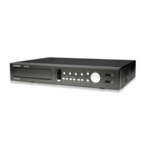
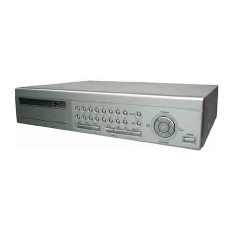
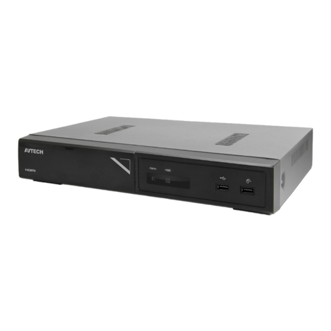
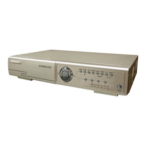
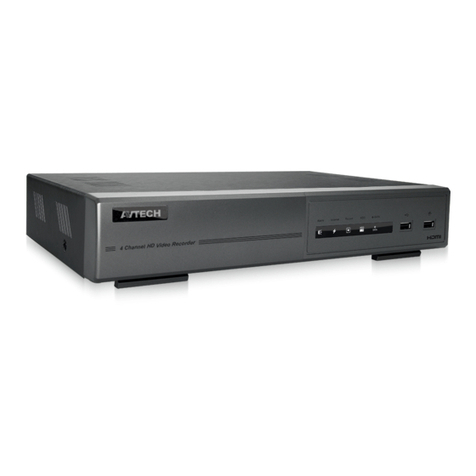
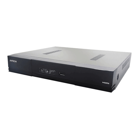
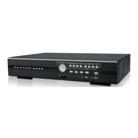
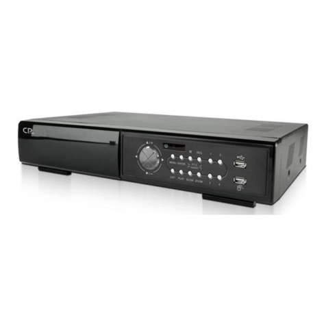
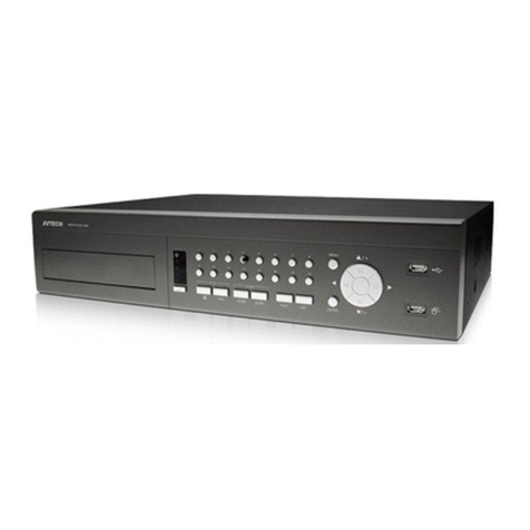
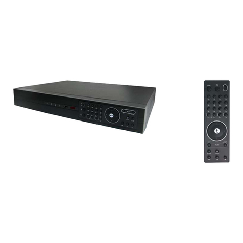
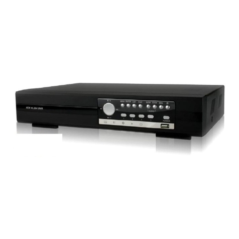
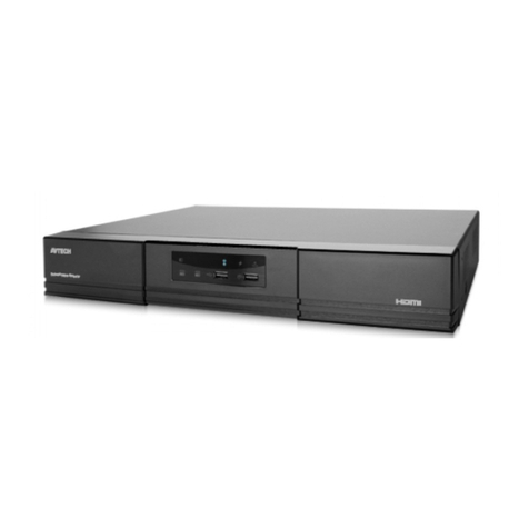
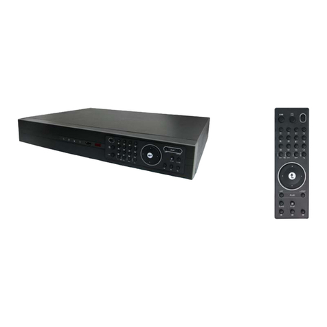
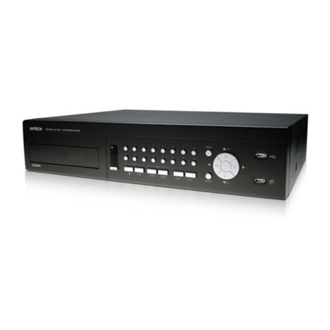
Avtech CPD560 User manual

149
ENGLISH 782, 781, 760, 761, 782A, 502, 501, 560, 561, 502A_V1.3
Please read instructions thoroughly before operation and retain it for future reference.
The image shown above may differ from the actual product appearance.

-1-
1 FUNCTION...........................................................................................................................................1
1.1. PACKAGE CONTENT .............................................................................................................................................1
1.2 FRONT PANEL.........................................................................................................................................................2
1.3 REAR PANEL ...........................................................................................................................................................5
2 GETTING STARTED............................................................................................................................7
2.1 GETTING STARTED ................................................................................................................................................7
2.2 SYSTEM TIME SETUP.............................................................................................................................................7
3. BASIC OPERATION...........................................................................................................................8
3.1 RECORDING............................................................................................................................................................8
3.2 PLAYBACK...............................................................................................................................................................8
APPENDIX 1 INSTALL HDD...................................................................................................................9
APPENDIX 2 PIN CONFIGURATION ...................................................................................................10
1.1. PACKAGE CONTENT
ITEMS Model 1 Model 2 Model 3 Model 4 Model 5
Digital Video Recorder (DVR)
Adapter and Power Cord
CD Manual & Hard Copy Quick Start
Free Licensed Software AP Disc
Free Compact Disc (CD) - - -
Screws * 4
DSUB PIN Connector
IR Receiver & Transmitter - - -
* Please check the package contents to make sure that you receive all accessories shown above.

-2-
1.2 FRONT PANEL
1) LED Indication
The following LEDs will be on when:
HDD: HDD is reading or recording
HDD Full: HDD is full.
ALARM: Once the alarm is triggered
TIMER: When timer recording is turned on
PLAY: Under playing status
REC: Under recording status
2) MENU
Press “MENU” button to enter the main menu.
3) ENTER / SET
Press “ENTER” button to confirm the setting.
Press “SET” to change the position of the channel display.
Press up/down/left/right direction buttons to select the channel that you want to change.
Press ““ or ““ to select the channel which You would like to show.
Channel Display Position
Under the live mode, you can switch the positions of two channels in the following way:
Step1:Press “Set” to highlight one channel.
Step2:Press “UP“, “DOWN”, “LEFT”, “RIGHT” button to move the highlight to the
channel you want to change its position.
Step3:Press “” or “” to select the channel you want to switch its position with the
one selected in Step2.
Step4:Press “ENTER” button to confirm the setting. For example, the position of CH2
& CH4 is switched as shown on the right side.
Under the playback mode, you can select a channel to display the live video instead of the playback video:
Step1:Press “Set” to highlight one channel.
Step2:Press “UP“, “DOWN”, “LEFT”, “RIGHT” button to move the highlight to the
channel you want to view the live video.
Step3:Press “” or “” to select the channel you want to view its live video.
Step4:Press “ENTER” button to confirm the setting. For example, CH2 playback view
is replaced with CH4 live view as shown on the right side.
4) SEARCH
Press “SEARCH” button to enter the search menu.
5) SLOW
Under the playback mode,
Model 1, 2 & 5: Press “SLOW” button to get 1/4X speed playback and press twice to get 1/8X speed playback.
Model 3 & 4: Press “SLOW” button to get 1/2X speed playback.
6) ZOOM
Press “ZOOM” button to enlarge the picture of selected channel (under the live mode).
01
03
Under Live Mode
01
03 04
Under Playback Mode
-3-
7) /
Press “ ” button to show the 4 channel display modes.
Press “” button to change the setting in the menu.
8) SEQ /
Press “SEQ” button to activate the call monitor function, and press again to quit.
Press ”” button to change the setting in the menu.
9) or POWER
Press this button long enough to turn on/off your DVR.
10)“CH1” “CH2” “CH3” “CH4”
Press one of the buttons to select the channel to display.
11)REC
Press “REC” button to activate manual recording.
12) or PLAY
Press this button to play the recorded video.
13)UP / PAUSE, DOWN / STOP, LEFT / REWIND, RIGHT / FORWARD,
Press one of the direction buttons to move the cursor up/down/left/right.
Under the playback mode:
Press “ ” or “ ” button to pause / stop playback. Press “ ” or “ ” button to fast rewind / forward.
14)
SLOW ZOOM
AUDIO
or (Audio)
Press these two buttons at the same time to select live or playback sounds of the audio channels.
15)
SEQ.
P.T.Z
or (PTZ)
Press these two buttons at the same time to enter / exit the PTZ control mode.
In the PTZ control mode Zoom in: Press "" button ; Zoom out: Press "" button
Adjust PTZ angle: Press direction buttons to turn up/down/left/right
16)Switch NTSC / PAL System
Press “ ” or “POWER” button on the DVR front panel to shutdown the DVR.
After shutdown the DVR, press and hold (switch to NTSC) or (switch to PAL) first, then press the power button
again to reboot the DVR (press until the monitor shows video images).
!"#$
!"#
17)Key Lock

-4-
Press “MENU” + “ENTER” on the DVR front panel at the same time to lock keys and to log in with another user name.
18)Open / Close the CD Writer
For Model 1 and Model 5, press “ ” button to open / close the CD Writer.

-5-
1.3 REAR PANEL
MODEL 1
1
LOOP
EXT ERNA L I/O
INPUT
2
LO OP LOOP LOOP
3
INP UT
4
INP U T
LAN
ACT.
LINK
1
CALLMONIT OR
IN OUT
2
DC 19V
USB
INPUT
VD /
MODEL 2
DC19V
1
LO O P
EXTERNAL I/O
INP UT
2
LOO P LO O P LOOP
3
INP U T
4
INP UT
LAN
ACT.
LINK
1
CA LLMO NIT OR
IN OUT
2
USB
INP UT
VD /
MODEL 3
INP UT
DC 19V
VD /
1
LOOP
EXTERNAL I/O
INPUT
2
LOOP LOOP LOOP
3
INP UT
4
INP UT
LAN
ACT .
LINK
1
CALLMONIT OR
IN OUT
MODEL 4
USB
INP UT
DC 19V
VD /
1
LOOP
EXTERNAL I/OIR
INPUT
2
LOOP LOOP LOOP
3
INP UT
4
INP UT
LAN
ACT .
LINK
1
CALLMONIT OR
IN OUT
MODEL 5
1
LOOP
EXT ERN AL I/O
INP U T
2
LOOP LOO P LOOP
3
INP UT
4
INP U T
LAN
A CT .
LINK
1
CA LLM ONIT O R
IN OUT
2
DC 19V
USB
INP U T
VD /IR

-6-
1) 75/ HI-IMPEDANCE
When using LOOP function, please switch to HI-IMPEDANCE. Otherwise, please switch to 75.
19)LOOP / INPUT (For channel 1~4)
LOOP: Video output connector.
INPUT: Connect to video sources, such as cameras.
%&'
()*+,-%!) %!*
(.+/-%!)
20)MONITOR
Connect to MAIN monitor.
21)CALL
Connect to CALL monitor to show the channel display one by one.
When any alarm is triggered, CALL monitor will show the image of the triggered channel for a period of time.
22)Audio IN
Connect to audio sources, such as cameras equipped with the audio function.
When users start recording, the audio input will also be recorded.
23)Audio OUT
Connect to a monitor or speaker with 1 mono audio output.
24)USB (For MODEL 1, 2, 4 & 5)
Support USB flash drive firmware update and file backup.
25)D/V Port (Digital Video Port)
Connect to VGA connecter.
26)IR (For Model 4 & 5)
Connect the IR receiver for remote control.
27)EXTERNAL I/O
Insert the supplied 15PIN DSUB to this port for connecting external devices (external alarm, PTZ camera, etc).
For detailed I/O port PIN configuration, please refer to “ 2 PIN ” at page 16.
28)LAN
Connect to Internet by LAN cable.
29)LINK ACT.
When your DVR is connected to the Internet, this LED will be on.
30)DC 19V
Connect to the supplied adapter.

-7-
2.1 GETTING STARTED
Connect all the devices to construct a surveillance system.
1. Install HDD:
The HDD must be installed before the DVR is turned on. Please refer to Appendix #1 for HDD installation instructions.
2. Connect cameras, monitors and external devices. Please refer to the section “1.3 REAR PANEL” for connection, and
Appendix#2 for pin configurations of the external I/O port.
$01
!
3. Connect the AC power cord to power adapter and plug into an electrical outlet.
The “ “ or “Power” LED will be on as red.
Press the “ ” or “Power” button. The “ “ or “Power” LED will be on as green.
It takes approximately 10 to 15 seconds to boot the system.
4. Set the date and time on your DVR. Please DO NOT change the date or time on your DVR after the recording function
is activated. The recorded data will be disordered and you will not be able to find the recorded data to backup by time
search.
% ' 2
3
2.2 SYSTEM TIME SETUP
Go to “MENU” mode, move the cursor to “DATE”, and press “ENTER”. The screen will show the following options.
Please DO NOT change the date or time when the recording function is activated. See “2.1 GETTING STARTED” at P.6
for details.
MENU DATE
RECORD DATE 2006 – DEC - 01 12 : 15 : 30
TIMER FORMAT Y - M - D
DATE DAYLIGHT SAVING ON
ADVANCE
DAYLIGHT SAVING
START 4
TH
-SUN-MAR 24:00:00
END 4
TH
-SUN-OCT 24:00:00
ADJUST 01:00
Set the start time and end time, and adjust the daylight saving time in hour. The above example means during the
daylight-saving time period (starting from the 4th Sunday of March and ending on the 4th Sunday of October), the system
time will plus one hour.

-8-
3.1 RECORDING
This device offers three recording modes: manual record, event record and timer record. If the power is off
accidentally, the recorded video data will not be lost and is safely stored in the HDD. The device will return to the original
recording status after the power is on again.
MANUAL RECORD (continuous recording)
Recording is initiated by manually pressing “REC” button on the front panel.
This mode is indicated by the sign “” on the screen.
EVENT RECORD (triggered by motion and external alarm)
When this function is activated, the recording is triggered by motion or external alarms.
This mode is indicated by the sign " " (motion) or " " (external alarm) on the screen.
TIMER RECORD (scheduled time)
Recording is scheduled by TIMER function.
Indicated by the wording “TIMER RECORD” on the monitor.
Please DO NOT change the date or time when the recording function is activated. See “2.1 GETTING STARTED” at P.6
for details.
3.2 PLAYBACK
Press “ ” or “PLAY” button on the front panel, and the device will display the last recorded video.
4)5*&&%'
&67%".8*9.
:4)5* .8%";&&
Playback related operations are described below:
Fast Forward ( ) / Fast Rewind ( )
You can increase the speed for fast forward and rewind on this device. In the playback mode:
Press “ “ once to get 4X speed forward and press twice to get 8X speed, etc. And the maximum speed is 32X.
Press “ “ once to get 4X speed rewind and press twice to get 8X speed, etc. And the maximum speed is 32X.
Pause ( ) / Image Jog
Press “ “ button to pause the video playback.
In the Pause mode:
Press “ “ button once to get one frame forward.
Press “ “ button once to get one frame rewind.
Stop ( )
Pressing “ ” button under all circumstances will return this device to live monitoring mode.
Channel Display Mode
Display mode:
Press “ ” button to show the 4 channel display modes.
Full screen view:

-9-
Press one of the number buttons from 1-4 to show the selected channel in the full screen.
Slow Playback
Model 1, 2 & 5: Press “SLOW” button to get 1/4X speed playback and press twice to get 1/8X speed playback.
Model 3 & 4: Press “SLOW” button to get 1/2X speed playback.
Audio
Press
SLOW ZOOM
AUDIO
or buttons at the same time to select to play either live (L) or playback (P) sound.
AUDIO 1 (L) – 1
st
audio channel, live audio;
AUDIO 1 (P) – 1
st
audio channel, playback audio
AUDIO 2 (L) – 2
nd
audio channel, live audio (Only Model 1, 2 & 5 have AUDIO 2 option)
AUDIO 2 (P) – 2
nd
audio channel, playback audio (Only Model 1, 2 & 5 have AUDIO 2 option)
HDD Installation for Model 1 and 5
1 Loosen the screws on the upper cover and open the upper cover of the DVR
1) Screw out the HDD bracket. For the positions of the HDD bracket screws, please refer to the figure below.
*; <33:( "';
3) Screw HDD onto the HDD bracket, two screws for each side. There are three screw holes per side on the bracket and
you can choose two of them to secure the HDD. And then screw the HDD bracket back to the DVR base.
4) Connect the HDD to the power connector and IDE BUS (make sure to align the HDD precisely for pin connection). And
then close the upper cover of the DVR and fasten all the screws you loosened in the step 1.

208
HDD Installation for Model 2, 3 and 4
2 Loosen the screws on the upper cover and open the upper cover of the DVR.
5) Screw out the HDD bracket.
=; <33:;
7) Screw HDD onto the HDD bracket, two screws for each side. And then screw the HDD bracket back to the DVR base.
(Refer to Fig.1 & 2).
8) Connect the HDD to the power connector and IDE BUS (make sure to align the HDD precisely for pin connection)
(Refer to Fig. 3)
9) Close the upper cover of the DVR and fasten all the screws you loosened in the step 1. (Refer to Fig. 4 & 5)
RS232-TX
RS232-RX
ALARM INPUT
EXTERNAL ALARM NC
EXTERNAL ALARM NO.
GND
RS485-B
RS485-A
PIN OFF
ALARM RESET
EXTERNAL ALARM COM
GND

208
782, 781, 760, 761, 782A, 502, 501, 560, 561, 502A_V1.3

208
782, 781, 760, 761, 782A, 502, 501, 560, 561, 502A_V1.3
!"#$%&'()*+,-./01234
56789:;

-1-
1
..............................................................................................................................................1
1.1. <= .................................................................................................................................................................1
1.2 >?) ..................................................................................................................................................................3
1.3 @?) ..................................................................................................................................................................7
2
............................................................................................................................................10
2.1 AB ................................................................................................................................................................10
2.2 CDEFGH .........................................................................................................................................................10
3.
...........................................................................................................................................12
3.1 I ........................................................................................................................................................................12
3.2 J K ........................................................................................................................................................................12
1
....................................................................................................................................14
2 PIN
.....................................................................................................................................16
1.1.
Model 1 Model 2 Model 3 Model 4 Model 5
LMKI (DVR) NNNNN
OPQRSTU NNNNN
)RVWX$= NNNNN
YZ[\]^ AP NNNNN
YZ_` N- - - N
a b 4cNNNNN

-2-
DSUB PIN def NNNNN
IR egURhiQ - - - NN
*
!

-3-
1.2
2) LED jkl
mno0pqrELED jklstu
HDDvwx#yz{
HDD Fullv|}
ALARMm~n
TIMERm I E
PLAYJ K
RECI
3)
p “MENU” ;
4) ENTER / SET
p “ENTER” GH
p “SET” jkM
/p//jkM
“” “” jk¡¢
jkM
1 “Set” y£¤
2 “UP“¥“DOWN”¥“LEFT”¥“RIGHT” ¦y§k¦¨©ª«M
3 “” “” «¬ 2yR®cM¯
4p “ENTER” GH°±¬ CH2 RCH4 M¯±²k
01
03
"$#&%('*),+
"$#&%('*),+"$#&%('*),+
"$#&%('*),+

-4-
!"#$%&$%
!"#$%&$% !"#$%&$%
!"#$%&$%
1 “Set” y£¤
2 “UP“¥“DOWN”¥“LEFT”¥“RIGHT” ¦y§k¦¨©ª«M
3 “”“” ¬³´µ¶·¸E¹>
4p “ENTER” GH°±CH2 JK¹>0µ CH4 ¸E¹>±²k
5) º »
“SEARCH” º »
6) SLOW
J K ¼½p
Model 1¥Model 2 RModel 5J K ¼½p¤ p “SLOW” 0 1/4X X¾¿XJKIIÀÁp0
1/8X X¾¿XJK
Model 3 RModel 4J K ¼½p “SLOW” 0 1/2X X¾¿XJKIIÀ
7) ZOOM
“ZOOM” LMK¹> (¸ E¼½p)
01
03 04
".-0/1'*),+
".-0/1'*),+".-0/1'*),+
".-0/1'*),+

-5-
8) /
“ ” j k 4ÃĹ>jk¼½
“” OGHÅ
9) SEQ /
“SEQ” ÆÇ ¼½È ¤ É Ê A ÆÇ ¼½
“” OGHÅ
10) POWER
Ë-Ì Í /ÎÏ© DVR
'
''
'
I ¼½pÎ Ð DVR ÑÒÓÔI
11) “CH1” “CH2” “CH3” “CH4”
¶¤cÕjk³¹>
12) I
“REC” . I
13) PLAY
-Ö×JKIIÀ
14)UP / PAUSE¥DOWN / STOP¥LEFT / REWIND¥RIGHT / FORWARD,
¶Ñ¤ÕiØÙ§¦
J K ¼½p
“ ” “ ” Ú Ó J K /ÓÔJK“ ” “ ” W X Û Ü /WÝ
15)
SLOW ZOOM
AUDIO
(Þ ß )
àEËáÁcâãäÞßåæK¸EJKÞß
16)
SEQ.
P.T.Z
(PTZ)
àEË-Ác/Æç PTZ iؼ½

-6-
PTZ iؼ½p èK  "" é ê ë ""
ì í PTZ î ¾ Õ iØ PTZ ï I /p// Ý
17) NTSC/PAL C D
DVR ð>>? “ ” “POWER” ¬ DVR Î
DVR Î 2 Ë ñ K (¨ NTSC C D )Ë ñ K (¨ PAL C D )ò 2 È ËS T
DVR (ËñKÌÍóôjkIõ¹>)
'
''
'
DVR sö÷ø PAL/NTSC CDù©ú0. PAL RNTSC CD
18) û
àEË DVR ð>>? “MENU” R“ENTER” û * 0 ¶ · ü ý
19)A /Î Ï CD þ
Model 1 RModel 5 “ ” A /Î Ï CD þ

-7-
1.3
MODEL 1
1
LOOP
EXT ERNA L I/O
INPUT
2
LO OP LOOP LOOP
3
INP UT
4
INP UT
LAN
ACT.
LINK
1
CALLMONIT OR
IN OUT
2
DC 19V
USB
INPUT
VD /
MODEL 2
DC19V
1
LO O P
EXTERNAL I/O
INP UT
2
LOO P LO O P LOOP
3
INP U T
4
INP UT
LAN
ACT.
LINK
1
CA LLMO NIT OR
IN OUT
2
USB
INP UT
VD /
MODEL 3
INP UT
DC 19V
VD /
1
LOOP
EXTERNAL I/O
INPUT
2
LOOP LOOP LOOP
3
INP UT
4
INP UT
LAN
ACT .
LINK
1
CALLMONIT OR
IN OUT
MODEL 4
USB
INP UT
DC 19V
VD /
1
LOOP
EXTERNAL I/OIR
INPUT
2
LOOP LOOP LOOP
3
INP UT
4
INP UT
LAN
ACT .
LINK
1
CALLMONIT OR
IN OUT
MODEL 5
1
LOO P
EXT ERNAL I/O
INP U T
2
LOOP LO OP LOOP
3
INP UT
4
INPU T
LAN
A CT.
LIN K
1
CALLMONIT OR
IN OUT
2
DC 19V
USB
INP U T
VD /IR
Table of contents
Languages:
Other Avtech DVR manuals

Avtech
Avtech 715ZC User manual

Avtech
Avtech avh-312 User manual

Avtech
Avtech KPD674 User manual

Avtech
Avtech DR163Z User manual

Avtech
Avtech AVC791A User manual

Avtech
Avtech KPD673 User manual

Avtech
Avtech DGD8132 User manual

Avtech
Avtech DG1648 Assembly instructions

Avtech
Avtech DG1648 User manual

Avtech
Avtech AVC799B User manual

Avtech
Avtech AVC798 User manual

Avtech
Avtech AVC792PV User manual

Avtech
Avtech AVC708H User manual

Avtech
Avtech AVH364 User manual

Avtech
Avtech avh-312 User manual

Avtech
Avtech AVC796 User manual

Avtech
Avtech AVC794 User manual

Avtech
Avtech AVH304 User manual

Avtech
Avtech AVC798 User manual

Avtech
Avtech AVH0401 User manual