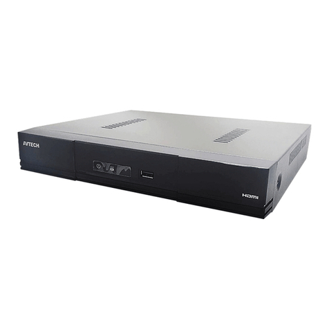
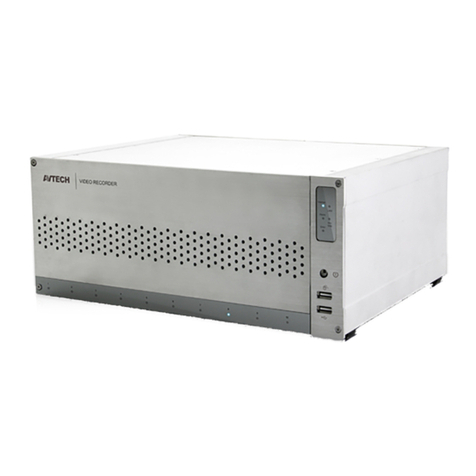
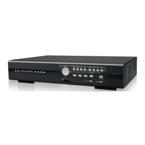
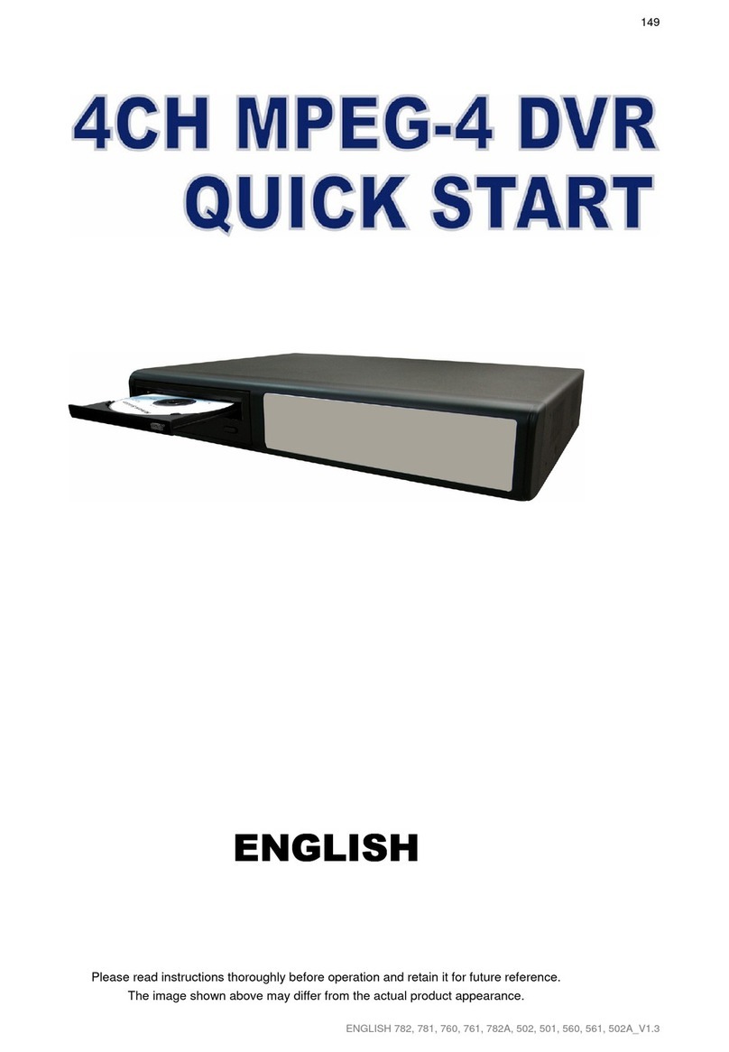
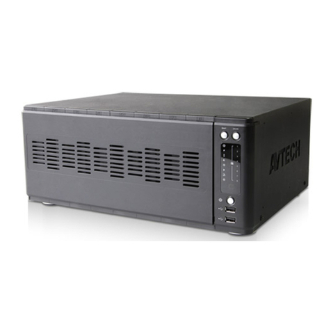
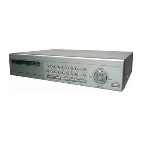
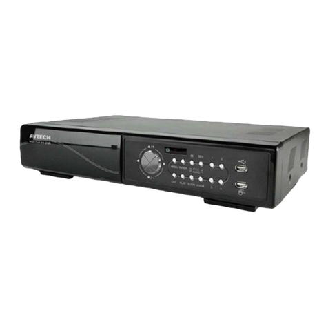
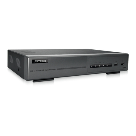
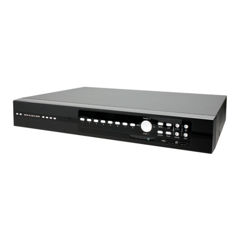
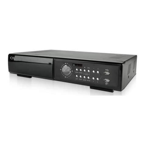
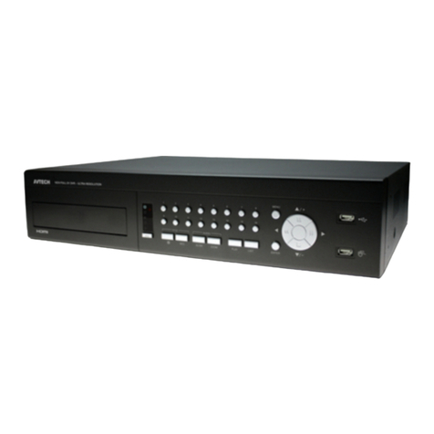
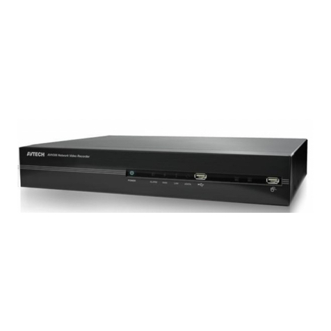
Avtech KPD Series User manual

234Z
616, 616F, 608, 608F, 604, 604F quick_V1.7
KPD Series
MPEG-4 DVR QUICK
Please read this instruction thoroughly before operation and retain it for future reference.
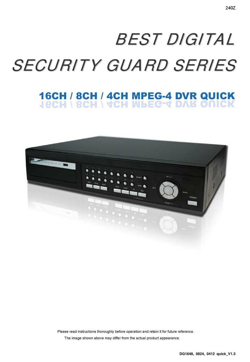
The image shown above may differ from the actual product appearance.
A
ll lead-free products offered by the company comply with the requirements of the European law on
the Restriction of Hazardous Substances (RoHS) directive, which means our manufacture processes
and products are strictly “lead-free” and without the hazardous substances cited in the directive.
The crossed-out wheeled bin mark symbolizes that within the European Union the product must be
collected separately at the product end-of-life. This applies to your product and any peripherals
marked with this symbol. Do not dispose of these products as unsorted municipal waste.
ROHS AND WEEE

1-
1. Package Contents
1.1 Package Contents
□Digital video recorder (DVR) □Thermal conductive silicone rubber
□Adapter and power cord □HDD bracket screws * 8 (spare parts)
□Free licensed software AP disc □DSUB PIN connector
□Manual & quick start & IR remote control manual □AAA size battery * 2
□Vertical panel sticker for remote controller (certain models only)
Note: Before using the IR remote controller, please install the batteries first.
2. FRONT AND REAR PANELS
2.1 Front Panel
1) LED Indication
The following LEDs will be on when:
: Power is connected : HDD is reading or recording / HDD Full: HDD is full
: Any event alarm is triggered : Timer recording is activated
Note: To turn off your DVR, please disconnect the power supply.
2) (USB port)
To quickly backup or upgrade firmware/OSD, you can insert a compatible USB flash drive into this USB port. Before
using the USB flash drive, please use your PC to format the USB flash drive as “FAT32” first.
Note: For the list of compatible USB flash drives, please refer to “Appendix 2” in the user manual.
3) IR receiving zone
If the control panel is removed from the DVR and used as a remote controller, aim the remote controller at this area
to control the DVR operation.
4) (Lock mode) / (Unlock mode)
To lock the remote controller back to the DVR, switch the lock button to the left “ ” (lock mode).
To remove the control panel from the DVR and use as a remote controller, switch the lock button to the right “ ” (unlock mode).
Note: Because of the different panel layout, please place the vertical panel sticker on the controller for
operation convenience.
5) (Menu)
Press this button to enter / exit the quick start menu.
In the sub-layer of the advanced setting menu,
press this button to confirm the settings and go back to the upper layer.
6) LIVE
Press this button to stop the playback and return to the live mode.
7) Channel Display Selection
‧ 16CH DVR
/ / / (Quad selection mode)
Under the live or playback mode, press one of these four buttons to select the quad display mode.
: Display Quad 1 mode (4-cut view of CH1, CH2, CH5 and CH6). : Display Quad 2 mode (4-cut view of CH3, CH4, CH7 and CH8).
: Display Quad 3 mode (4-cut view of CH9, CH10, CH13 and CH14). : Display Quad 4 mode (4-cut view of CH11, CH12, CH15 and CH16).

2-
/ / / (Channel selection under quad selection mode)
In the quad display mode, press one of these four buttons to select the channel display.
: Display the upper left channel of the selected quad mode. : Display the upper right channel of the selected quad mode.
: Display the lower left channel of the selected quad mode. : Display the lower right channel of the selected quad mode.
‧ 8CH DVR
/ / / / / / / (Channel selection)
Press one of these buttons to select the channel display CH1 ~ CH8.
‧ 4CH DVR
/ / / (Channel selection)
Press one of these buttons to select the channel display CH1 ~ CH4.
8) / / or (16-cut channel display / 9-cut channel display / 4-cut channel display)
Press one of these buttons to switch the channel display.
: Display 16-cut display (for 16CH DVR). : Display 9-cut display (for 16CH, 8CH DVR).
: Display 4-cut display (for 8CH DVR). : Display 4-cut display (for 4CH DVR).
9) / (Quad Sequence / Full Sequence)
Press one of these buttons to activate the sequence mode.
: Press this button to activate the Quad Sequence mode and press the button again to exit.
: Press this button to activate the Full Sequence mode and press the button again to exit.
10)
1
2
3/
4
5
6/
7
8
9/
0
A
B(Number buttons for password entering)
Use these four buttons to enter the DVR password.
11) /
Use these two buttons to select the live or playback sound of the audio channels.
Icon “ ” means: Live audio of the 1st audio channel / Icon “ ” means: Playback audio of the 1st audio channel
Icon “ ” means: Live audio of the 2nd audio channel / Icon “ ” means: Playback audio of the 2nd audio channel
Icon “ ” means: Live audio of the 3rd audio channel / Icon “ ” means: Playback audio of the 3rd audio channel
Icon “ ” means: Live audio of the 4th audio channel / Icon “ ” means: Playback audio of the 4th audio channel
Icon “ ” means: The audio channel is not selected.
Note: If you want to make a video backup with audio, please connect audio cameras to the channels
which support the audio function
For 16CH & 8CH DVR, the audio channels are CH1, CH2, CH3 and CH4.
For 4CH DVR with a fan built-in, the audio channel is CH1.
12) (Key lock)
Press this button to lock keys on the DVR front panel.
13) (Digital zoom)
Press this button to enlarge the image of the selected channel.
14) ▲/ ▼/ ◄/ ►
Press one of these direction buttons to move the cursor up/down/left/right.
Under the DVR menu mode, these direction buttons can use for the following operation:
▲▼: Make the selection / Change the settings ◄►: Go to the upper layer or sub-layer / Make the selection

3-
15) (Enter)
Confirm the password entering.
In the advanced menu, press this button to confirm the settings and go back to the upper layer.
16) LIST (Event List Search)
To quick search the recorded files by event list, press this button to show all types of the event lists.
ALARM: List the information of the alarm-trigger-recorded files.
MANUAL: List the information of the manual-recorded files. The DVR will save one recorded file once any recording setting is changed
MOTION: List the information of the motion-trigger-recorded files.
SYSTEM: List the information of the system-recorded files. The DVR system will save one recorded file every one hour.
TIMER: List the information of the timer-recorded files.
17) LATEST
Press this button to playback the latest recorded video.
18) STOP
Press this button to stop playback and return to the live mode.
19) SLOW
Under the playback mode, press this button to slowly playback the recorded file (by 1/4 speed or 1/8 speed).
20) ◄◄ / /►►
Under the playback mode, press these buttons to fast rewind / pause / fast forward the playback file.
2.2 Rear Panels
‧ 16CH (The fan is optional)
RISK OF ELECTRICS HOCK
DO NOT OPEN
DC19V
WARNING : TOREDUCE THE RISKO FELECTRIC SHOCK,
DO NOT REMO V E C OVE R ( OR BA CK ).
NO U SER-SERVI CEABL E PARTS IN SIDE.
REFER SERVICI NG TOQUALIFIED
SERVICE PERSONNEL.
ACT.
LINK
LAN
EXTERNAL I/O
IR
RS485
142356 78910 11 12 13 14 15 16 MONITOR 12341
‧ 8CH (The fan is optional)
RIS K OF EL ECT RIC S HO CK
DO NOT OPEN
DC19V
WARNING : TO REDUCE THE RISK OF ELECTRIC SHOCK,
DO NOT REMO V E C OVE R ( OR BA CK ).
NO U SER-SERVI CEABL E PARTS IN SIDE.
REFER SERVICI NG TOQUALIFIED
SERVICE PERSONNEL.
ACT.
LINK
LAN
EXTERNAL I/O
IR
RS485
14
235678MONITOR 12
341
‧ 4CH (The fan is optional)
EX TERN AL I/ O LAN
LINK
ACT.
MONITOR
DC 19V
OUTIN
1234
IR
1) INPUT (1 ~ 16CH)
Connect to video sources, such as cameras.
Note: The DVR will automatically detect the video system of the camera, please make sure that the
cameras are properly connected to the DVR and power-supplied before the DVR is turned on.
Note: If you want to make a video backup with audio, please connect audio cameras to the channels
which support the audio function.
For 16CH & 8CH DVR, the audio channels are CH1, CH2, CH3 and CH4.
For 4CH DVR, the audio channel is CH1.

4-
2) MONITOR
Connect to a CRT monitor for video output.
3) Audio IN (1 / 2 / 3 / 4)
Connect to audio sources, such as cameras equipped with the audio function.
When users start recording, the audio input will also be recorded with corresponding video channel.
Note: The audio source connected to the “Audio 1” will be recorded with the video of the “CH1”.
The audio source connected to the “Audio 2” will be recorded with the video of the “CH2”.
The audio source connected to the “Audio 3” will be recorded with the video of the “CH3”.
The audio source connected to the “Audio 4” will be recorded with the video of the “CH4”.
4) Audio OUT
Connect to a monitor or speaker with 1 mono audio output.
5) IR
Connect the IR receiver extension line for remote control.
6) EXTERNAL I/O
Insert the supplied 25PIN DSUB to this port for connecting external devices (external alarm, etc).
For detailed I/O port PIN configuration, please refer to “APPENDIX 1 PIN CONFIGURATION” in the user’s manual.
7) LAN
Connect to Internet by LAN cable.
8) LINK ACT.
When your DVR is connected to the Internet, this LED will be on.
9) DC 19V
Connect to the supplied adapter.
10)Fan (Optional)
The fan equipment is optional.
3. CONNECTIONS AND SETUP (Take 16CH DVR as an example)
3.1 HDD Installation
The HDDs must be installed before the DVR is turned on.
Step 1: Loose the screws on the upper cover and open the upper cover of the DVR.
Step 2: Screw out the L-shape HDD brackets. Two brackets are used to secure a HDD, and there are 4 of them.
Step 3: Paste the thermal conductive silicone rubber on the DVR base.
Step 4: Get a suitable brand HDD and set the HDD mode (Master or Slave).
Note: HDD mode setting rule:
Master if you want to install the HDD to the place near the back panel;
Slave if you want to install the HDD to the place near the front panel.
Step 5: Attach the bracket to one side of the HDD, and align the screw holes of the bracket with the HDD’s screw holes.
Screw the HDD onto the HDD bracket, two screws for each side. Then, do the same thing to the other side of the HDD.
Step 6: Screw the two HDD brackets back to the DVR base.
Step 7: Connect the HDD to the power connector and IDE BUS (make sure to align the HDD precisely for pin connection).
Make sure the HDD mode is set to “Master” or “Slave” as indicated below for the IDE BUS connection.
Step 8: Close the upper cover of the DVR, and fasten all the screws you loosened in Step 1.

5-
3.2 Camera Connection
The cameras must be connected and power-supplied BEFORE the DVR is turned on. The DVR will automatically
detect the video system of the connected camera(s) (NTSC / PAL), and switch itself to the correct system.
Connect the camera with the indicated power supply, and connect the camera video output to the DVR video input
port with a coaxial cable or RCA lines with BNC connectors.
Note: For detailed DVR video input / output ports, please refer to “2.3 Rear Panel” in the user’s manual.
For detailed camera operation, please refer to its own manual.
Note: If you want to make a video backup with audio, please connect audio cameras to the channels
which support the audio function
For 16CH & 8CH DVR, the audio channels are CH1, CH2, CH3 and CH4.
For 4CH DVR with a fan built-in, the audio channel is CH1.
3.3 Power Setup
This device should be operated only with the type of power source indicated on the manufacturer’s label. Connect
the indicated AC power cord to the power adapter, and plug into an electrical outlet. Power LED “ ” will be on as blue.
It takes approximately 10 to 15 seconds to boot the system.
3.4 Date and Time Setting
Before operating your DVR, please set the date and time on your DVR first.
Press (menu) button and enter the password to go to the quick-start menu list. The default admin password is
0000. Move the cursor to the icon and you can set the date / time / daylight saving in this menu list.
QUICK START
CHANNEL TITLE ON
EVENT STATUS ON
IMAGE SIZE CIF
QUALITY BEST
IMAGE PER SECOND 120
RECORD TIMER OFF
DETECTION TIMER OFF
DATE 2007 / AUG / 08 21 : 30 : 00
FORMAT Y / M / D
DAYLIGHT SAVING OFF
ADVANCE uv SELECT sBACK tNEXT ENTER
Note: If the time and date settings return to their default values after the DVR is rebooted, please charge
the DVR for at least 24-48 straight hours. Please contact your local retailer if the situation still occurs.

6-
3.5 Password Setting
Press (menu) button and enter the password to go to the quick-start menu list. And then move the cursor to
“ADVANCE” to enter the advanced setting menu.
In the “ADVANCE” menu, move the cursor to “ SYSTEM INFO ”. Select “PASSWORD” and press (enter)
button to enter the submenu to set the password (four digits). The default admin password is 0000.
SYSTEM INFO
SERIAL TYPE RS485
BAUD RATE 2400
HOST ID 0
PASSWORD XXXX
RESET DEFAULT RESET
CLEAR HDD HDD-MASTER-1
UPGRADE START
AUTO KEYLOCK (SEC) 30
LANGUAGE ENGLISH
VIDEO FORMAT NTSC
VERSION 1049-1007-1011-1001-L6-6C1B
PLEASE CONSULT YOUR INSTALLER FOR ADVANCE SETTINGS
uv SELECT sBACK tNEXT ENTER
4. BASIC OPERATION (Take 16CH DVR as an example)
4.1 Live Page
In this live page of the DVR, you can see the live viewing of 1- / 4- / 9- / 16-cut screen.
Icon Function Icon Function Icon Function Icon Function
Key lock Key unlock 1st live audio
channel
2nd live audio
channel
3rd live audio
channel
4th live audio
channel
Audio channel
unselected Digital zoom mode
Digital zoom
unselected Timer recording Motion Recording
Alarm
4.2 Recording
When the recording and the pre-alarm function are activated, this device will overwrite 8GB data from the oldest
for continuous recording without notice.
1) Continuous Recording Icon
When the DVR is properly connected with camera, you can see the icon “ ” (recording) on the screen.
2) Event Recording Icon
When the motion / alarm detection is activated, once motion or external alarm happens, you will see the icon “ ”
(motion) or “ ” (external alarm) on the screen.

7-
3) Timer Recording Icon
When the timer record is activated, you will see the icon “ ” (timer) on the screen.
Note: The audio source connected to the “Audio 1” will be recorded with the video of the “CH1”.
The audio source connected to the “Audio 2” will be recorded with the video of the “CH2”.
The audio source connected to the “Audio 3” will be recorded with the video of the “CH3”.
The audio source connected to the “Audio 4” will be recorded with the video of the “CH4”.
Note: A new log will be added in the system log when the HDD data is overwritten or the recording starts after DVR reboots.
4.3 Playback
Press the “LATEST” button on the DVR control panel, and the device will playback the latest recorded video.
Note: There must be at least 8192 images of recorded data for playback to work properly. If not, the
device will stop playback. For example, if the IPS is set to 30, the recording time should be at least
273 seconds (8192 images / 30 IPS) for the playback to work properly.
1) Fast Forward (►►) / Fast Rewind (◄◄)
You can increase the speed for fast forward and rewind on this device. In the playback mode:
Press “►►“ once to get 4X speed forward and press twice to get 8X speed, etc. And the maximum speed is 32X.
Press “◄◄“ once to get 4X speed rewind and press twice to get 8X speed, etc. And the maximum speed is 32X.
Note: During playback, the image size of the recording (Frame or CIF) will be shown on the screen.
2) Pause ( ) / Image Jog
Press “ ” button to pause the playback.
In the Pause mode:
Press “►►” button once to get one frame forward. Press “◄◄” button once to get one frame rewind.
3) Stop
Pressing “STOP” button under playback mode, the screen of this device will return to live monitoring mode.
4) Slow Playback
Press “SLOW” button to get 1/4X speed playback and press twice to get 1/8X speed playback.
5) Audio Playback ( / )
Use these two buttons to select the live or playback sound of the audio channels.
Icon “ ” means: Live audio of the 1st audio channel / Icon “ ” means: Playback audio of the 1st audio channel
Icon “ ” means: Live audio of the 2nd audio channel / Icon “ ” means: Playback audio of the 2nd audio channel
Icon “ ” means: Live audio of the 3rd audio channel / Icon “ ” means: Playback audio of the 3rd audio channel
Icon “ ” means: Live audio of the 4th audio channel / Icon “ ” means: Playback audio of the 4th audio channel
Icon “ ” means: The audio channel is not selected.
Note: If you want to make a video backup with audio, please connect audio cameras to the channels which support the audio function
For 16CH & 8CH DVR, the audio channels are CH1, CH2, CH3 and CH4.
For 4CH DVR with a fan built-in, the audio channel is CH1.
4.4 Key Lock and Unlock
1) Key Lock On:
Press button on the DVR control panel to lock keys.
Or set the time-out after which the key lock function is activated (Never / 10 SEC / 30 SEC / 60 SEC).
2) Key Lock Off:
Enter the DVR password to exit “Key Lock” mode.
Note: For the password setting, please refer to the section “3.5 Password Setting” in the user’s manual.
237Z
616、616F、608、608F、604、604F 簡易手冊_V1.6
KPD
系列
MPEG-4 數位錄放影機簡易手冊
在使用本機前請務必詳細閱讀安全須知及操作說明,並保存此手冊以備後續參考。
產品外觀以實機為主。
本公提供的所有無鉛產品皆符合歐盟有害物質使用限制指引 (Restriction of Hazardous Substances,
(RoHS)),
意即本公司的生產流程與產品均嚴格遵守無鉛守則
,
而且不包含該指引內提供的任何有害物
質。
此劃叉的滾輪垃圾筒圖示代表在歐盟境內,本產品於丟棄時必須另行收集。此原則適用於您的產品與
任何標有此圖示的週邊設備
。
請勿隨意丟棄這些產品
。
ROHS 和WEEE 符合聲明

1
1. 產品概述
1.1 包裝明細
□數位錄放影機 (DVR) □散熱片
□變壓器與電源線 □硬碟支架螺絲八顆 (備品)
□免費專利軟體 AP 光碟 □DSUB PIN 轉接頭
□說明書、簡易手冊和 IR 紅外線遙控器說明書 □3A 電池兩顆
□遙控器專用的直向面板貼紙 (僅限特定型號)
註:在使用 IR 紅外線遙控器之前,請記得先安裝電池。
2. 面板解說與背板解說
2.1 正面板
1) LED 顯示燈
當發生以下情形時,LED 顯示燈會亮起:
:當電源已連接 :硬碟讀取中或錄影中 / HDD Full:硬碟已滿
:當有任何事件或位移偵測警報被觸發 :當預約錄影已啟動
註:如果您想要關閉此 DVR,請將拔除電源線。
2) (USB 埠)
快速備份或申級韌體 / OSD,您可以將相容的 USB 隨身碟插入此 USB 埠。在使用 USB 隨身碟之前,請先使用您的
電腦將 USB 隨身碟格式化成 FAT32 的格式。
註:相容的 USB 隨身碟列表,請參閱說明書中的 “附錄 2 相容的 USB 隨身碟品牌”。
3) IR 接收區
如果您將 DVR 的控制面板取下當作遙控器使用,對準此 IR 接收區域以操控您的 DVR。
4) (上鎖模式) / (解鎖模式)
請將此鎖移至左邊 “ ” (上鎖模式) 以將控制面板鎖在 DVR 上。
如果您想要取下 DVR 的控制面板當作遙控器使用,請將鎖鍵移到右邊 “ ” (解鎖模式)。
註:因為面板的排列位置不同,請使用包裝內附的直向面板貼紙放置在取下的控制面板上,以方便您操作。
5) (目錄選單)
請按此按鍵進入 / 跳出快速選單。
在進階選單的子選單下,使用此按鍵確認設定並回到上一目錄選單階層。
6) LIVE (即時)
按此按鍵停止回放並回到即時畫面。
7) 頻道顯示選擇
‧ 16 路DVR
/ / / (四分割選擇模式)
在即時或回放的模式下,使用此四個按鍵選擇四分割畫面模式。
:顯示 “Quad 1 “ 模式 ( CH1、CH2、CH5 與CH6 的四分割畫面)。:顯示 “Quad 2 “ 模式 (CH3、CH4、CH7 與CH8 的四分割畫面)。
:顯示 “Quad 3 “ 模式 (CH9、CH10、CH13 與CH14 的四分割畫面)。:顯示 “Quad 4 “ 模式 (CH11、CH12、CH15 與CH16 的四分割畫面)。

2
/ / / (在四分割選擇模式下的頻道選擇)
在四分割畫面顯示模式下,按此四個之一的按鍵選擇頻道顯示。
:顯示選取的四分割模式中, “左上“ 位置的頻道。 :顯示選取的四分割模式中, “右上“ 位置的頻道。
:顯示選取的四分割模式中, “左下“ 位置的頻道。 :顯示選取的四分割模式中, “右下“ 位置的頻道。
‧ 8路DVR
/ / / / / / / (頻道選擇)
按其中一個按鍵來顯示頻道 CH1 到CH8。
‧ 4路DVR
/ / / (頻道選擇)
按其中一個按鍵來顯示頻道 CH1 到CH4。
8) / / 或 (16 分割頻道顯示 / 9 分割頻道顯示 / 4 分割頻道顯示)
按其中一個按鍵來切換頻道畫面。
:顯示 16 分割畫面 (僅限 16 路DVR)。:顯示 9分割畫面 (僅限 16 路和 8路DVR)。
: 顯示4 分割畫面 (僅限 8 路 DVR)。 : 顯示 4 分割畫面 (僅限 4 路 DVR)。
9) / (四分割跳台 / 單頻道跳台)
按其中一個按鍵來啟動跳台模式。
:按此按鍵啟動四分割跳台模式,再按一次跳出此模式。
:按此按鍵啟動單頻道跳台模式,再按一次跳出此模式。
10)
1
2
3/
4
5
6/
7
8
9/
0
A
B(用來編輯密碼的數字按鍵)
使用這些數字按鍵來輸入 DVR 密碼。
11) /
使用此兩個按鍵選擇聲音頻道的即時或回放聲音。
圖示 “ ” :1st 聲音頻道的即時聲音 / 圖示 “ ” :1st 聲音頻道的回放聲音
圖示 “ ” :2nd 聲音頻道的即時聲音 / 圖示 “ ” :2nd 聲音頻道的回放聲音
圖示 “ ” :3rd 聲音頻道的即時聲音 / 圖示 “ ” :3rd 聲音頻道的回放聲音
圖示 “ ” :4th 聲音頻道的即時聲音 / 圖示 “ ” :4th 聲音頻道的回放聲音
圖示 “ ” :聲音頻道未被選取。
註:如果您想要備份有聲音的錄影檔案,請將有收音功能的攝影機連接到支援聲音錄影的頻道 (CH1、CH2、CH3 與CH4)。
16 路和 8路DVR 的聲音頻道為 CH1、CH2、CH3 與CH4。
4路DVR 的聲音頻道為 CH1。
12) (按鍵鎖)
按此將 DVR 正面板的按鍵上鎖。
13) (數位放大)
按此按鍵將選取頻道的影像數位放大。
14) ▲/ ▼/ ◄/ ►
使用方向鍵移動游標上 / 下/ 左/ 右。
在DVR 的目錄選單模式下,這些方向鍵可以用來進行以下的操作:
▲▼:選擇 / 變更設定
◄►:到上一目錄選單階層或子目錄階層 / 設定值選擇

3
15) (輸入)
確認密碼輸入。
在進階選單下,使用此按鍵確認設定並回到上一目錄選單階層。
16) LIST (事件清單搜尋)
快速藉由事件清單尋找錄影檔案,按此按鍵顯示各種類型的事件清單。
警報:列出所有警報觸發錄影的檔案資訊。
手動:列出所有手動錄影的檔案資訊。只要任何錄影設定變更,DVR 會自動儲存一個錄影檔案
位移偵測:列出所有位移偵測觸發錄影的檔案資訊。
系統:列出所有系統錄影的檔案資訊。DVR 系統每一小時會儲存一個錄影檔案。
預約錄影:列出所有預約錄影的檔案資訊。
17) LATEST (最新之錄影檔案)
按此按鍵回放最新錄影之檔案。
18) STOP (停止)
按此按鍵停止回放並回到即時畫面。
19) SLOW (慢速回放)
在回放模式中,按此按鍵慢速回放錄影檔案 (1/4 或1/8 倍的速度)。
20) ◄◄ / /►►
在回放模式下,按此按鍵快速倒轉 / 暫停 / 快轉。
2.2 背板
‧ 16 路(風扇為選購配備)
RISK OF ELECTRICS HOCK
DO NOT OPEN
DC19V
WARNING : TO REDUCE THE RISK OF ELECTRIC SHOCK,
DO NOT REMO V E C OVE R ( OR BA CK ).
NO U SER-SERVI CEABL E PARTS IN SIDE.
REFER SERVICI NG TOQUALIFIED
SERVICE PERSONNEL.
ACT.
LINK
LAN
EXTERNAL I/O
IR
RS485
142356 78910 11 12 13 14 15 16 MONITOR 12341
‧ 8路(風扇為選購配備)
RIS K OF EL ECT RIC S HO CK
DO NOT OPEN
DC19V
WARNING : TO REDUCE THE RISK OF ELECTRIC SHOCK,
DO NOT REMO V E C OVE R ( OR BA CK ).
NO U SER-SERVI CEABL E PARTS IN SIDE.
REFER SERVICI NG TOQUALIFIED
SERVICE PERSONNEL.
ACT.
LINK
LAN
EXTERNAL I/O
IR
RS485
14
235678MONITOR 12
341
‧ 4路(風扇為選購配備)
EX TERN AL I/ O LAN
LINK
ACT.
MONITOR
DC 19V
OUTIN
1234
IR
1) INPUT 影像輸入 (1 ~ 16CH)
連接影像來源,如攝影機。
註:DVR 會自動偵測攝影機的影像系統,請確認攝影機正確連接至 DVR,並且在 DVR 開機之前,先將攝影機上電。
註:如果您想要備份有聲音的錄影檔案,請將有收音功能的攝影機連接到支援聲音錄影的頻道。
16 路和 8路DVR 的聲音頻道為 CH1、CH2、CH3 與CH4。
4路DVR 的聲音頻道為 CH1。

4
2) MONITOR (螢幕)
連接至 CRT 螢幕以輸出影像。
3) Audio IN 聲音輸入 (1 / 2 / 3 / 4)
連接到聲音來源,如支援收音功能的攝影機。
當使用者開始錄影,聲音輸入會與相對應頻道的影像錄在一起。
註:連接至 “Audio 1” 的音源輸入會與 “CH1” 的影像錄在一起。
連接至 “Audio 2” 的音源輸入會與 “CH2” 的影像錄在一起。
連接至 “Audio 3” 的音源輸入會與 “CH3” 的影像錄在一起。
連接至 “Audio 4” 的音源輸入會與 “CH4” 的影像錄在一起。
4) Audio OUT (音源輸出)
連接有喇叭功能的螢幕或是單聲道喇叭。
5) IR (遙控器)
連接到 IR 接收線,以 IR 遙控器進行遙控。
6) EXTERNAL I/O
插入產品包裝所附的 DSUB 25 PIN 的轉接頭,以連接外部設備 (如外部警報器…等)。
如需得知詳細的 I/O 埠PIN 解說,請參閱說明書的 “附錄 1 PIN 解說”。
7) LAN (網路)
以網路線來連上網際網路。
8) LINK ACT.
LED 燈亮時代表網際網路在連線狀態。
9) DC 19V
連接到電源變壓器(包裝盒內附)。
10) 風扇 (選購配備)
風扇裝置為選購配備。
3. 連接與安裝 (以16 路DVR 為例)
3.1 硬碟安裝
DVR 啟動之前請務必將硬碟安裝好。
步驟1: 鬆開 DVR 上蓋的螺絲,然後打開 DVR 上蓋。
步驟2: 鬆開 L型硬碟支架的螺絲。一顆硬碟使用兩個支架固定,共有四個支架。
步驟3: 將散熱片貼到 DVR 底部。
步驟4: 使用相容的硬碟並設定硬碟的模式 (Master 或Slave)。
註:硬碟模式設定規則:
Master:當您安裝硬碟的位置靠近背面板。
Slave:當您安裝硬碟的位置靠近正面板。
步驟5: 將支架與硬碟側邊的螺絲孔對齊。將硬碟支架分別鎖附在硬碟的兩側,一邊使用兩個螺絲。若您有安裝第二顆硬
碟,方式同第一顆硬碟。
步驟6: 將硬碟與硬碟支架鎖回 DVR 的內部底座。
步驟7: 將硬碟與電源排線與 IDE 排線連接 (請確認排線與硬碟後方的 PIN 腳對齊之後,再將排線插入硬碟的 PIN 孔)。
關於 IDE 排線的連接,請確認是否有依下圖指示,將硬碟模式設為 "Master" 或"Slave"。
步驟8: 闔上 DVR 上蓋,然後將您在步驟 1取出的螺絲鎖回去。

5
3.2 攝影機連接
在DVR 開機之前,請先確認攝影機已連接到 DVR 並已上電。DVR 會自動偵測連接攝影機的影像系統 (NTSC
/ PAL),然後再自己切換到正確的影像系統。
將攝影機連接至指定的電源線並上電。然後使用同軸電纜或接上 BNC 接頭的 RCA 線,連接攝影機的影像輸出至
DVR 的影像輸入。
註:詳細的 DVR 影像輸出 / 輸入埠資訊,請參閱說明書的 “2.3 背板”。
詳細的攝影機操作,請參閱攝影機的說明書。
註:如果您想要備份有聲音的錄影檔案,請將有收音功能的攝影機連接到支援聲音錄影的頻道 (CH1、CH2、CH3 與
CH4)。
16 路和 8路DVR 的聲音頻道為 CH1、CH2、CH3 與CH4。
4路DVR 的聲音頻道為 CH1。
3.3 電源設定
此設備操作必須使用製造者所標示的電源供應器類型。將指定的 AC 電源線接到變壓器,並將電源插頭插入電源插
座。電源 LED 顯示燈 “ ” 會亮藍色燈光。大約需要 10 到15 秒來啟動系統。
3.4 日期與時間設定
在操作 DVR 之前,請先設定 DVR 的日期與時間。
按(目錄選單) 按鈕並輸入密碼,即可進入快速選單。預設的 admin 密碼為 0000。將游標移到 圖示,就
可以在此功能清單中設定日期 / 時間 / 日光節約。
快速選單
頻道名稱 ON
事件狀態 ON
影像大小 CIF
錄影品質 最佳
錄影張數 120
預約錄影 OFF
預約位移偵測 OFF
日期 2007 / 08 / 08 21 : 30 : 00
格式 年/ 月/ 日
日光節約 OFF
進階 uv 選取 s上一個 t下一個 進入
註:若時間日期設定完畢,重新開機後卻又回復到出廠設定值,此時請將 DVR 連續上電 24~48 小時後,再觀察是否還
有此情形發生。

6
3.5 密碼設定
按(目錄選單) 按鈕並輸入密碼,即可進入快速選單。將游標移到 “進階”,即可進入進階選單。
在“進階” 目錄選單中,將游標移到 “ ” (系統資訊).選取 “密碼”,然後按 (進入) 按鈕進入子目錄選單即可
設定密碼 (四碼)。預設的 admin 密碼為 0000。
系統資訊
序列裝置類別 RS485
鮑率 2400
本機認證碼 0
密碼 XXXX
回復預設值 重設
清除硬碟 HDD-MASTER-1
升級 開始
自動按鍵鎖 (秒) 30
語言 中文
系統 NTSC
版本 1049-1007-1011-1001-L6-6C1B
進階設定請聯絡與諮詢您的安裝商
uv 選擇 s上一個 t下一個 進入
4. 基本操作 (以16 路DVR 為例)
4.1 即時畫面
DVR 的即時畫面可以看見 1、4、9或16 分割的畫面。
圖示 功能 圖示 功能 圖示 功能 圖示 功能
按鍵鎖 按鍵解鎖 第一個聲音頻道的
即時聲音 第二個聲音頻道的
即時聲音
第三個聲音頻道的
即時聲音 第四個聲音頻道的
即時聲音 未選取任何聲音
頻道 數位變焦模式
未選取數位變焦
模式 預約錄影 位移偵測 錄影中
警報
4.2 錄影
當錄影和警報前錄影的功能啟動且硬碟已滿時,本裝置會自動從最舊的資料開始覆寫 8GB 的錄影資料,讓錄影能持
續進行,不另行通知。
1) 持續錄影圖示
當DVR 與攝影機正確的連接時,您可以看見螢幕上出現 “ ” (錄影中) 的符號。
2) 事件錄影圖示

7
當位移偵測 / 警報偵測被觸發時,您會看見螢幕上出現 “ ” (位移偵測) 或“ ” (外接警報) 的圖示。
3) 預約錄影圖示
當預約錄影啟動時,您會看見螢幕上出現 “ ” (預約錄影) 的圖示。
註:連接至 “Audio 1” 的音源輸入會與 “CH1” 的影像錄在一起。
連接至 “Audio 2” 的音源輸入會與 “CH2” 的影像錄在一起。
連接至 “Audio 3” 的音源輸入會與 “CH3” 的影像錄在一起。
連接至 “Audio 4” 的音源輸入會與 “CH4” 的影像錄在一起。
註:當硬碟在執行覆寫,或 DVR 重新開機後系統開始錄影時,均會在事件紀錄裡添加一筆紀錄。
4.3 影像回放
按DVR 控制面板的 “LATEST” 按鍵,系統會回放最新錄影的檔案。
註:若要能正常回放錄影檔案,請至少必須錄超過 8192 張畫面。如果您尚未錄滿 8192 畫面就進行回放動作,DVR 將
會停止回放。例如,如果您將 IPS 設為 30,若要正常回放檔案,則錄影時間至少必須超過 273 秒 (8192 張影像 / 30 IPS)。
1) 快轉 (►►) / 快速倒轉 (◄◄)
您可以加快 DVR 快轉與倒轉的速度。在回放模式下:
按 “►►” 按鍵一次,DVR 會以 4倍的速度回放快轉畫面,按兩次,DVR 會以 8倍的速度…以此類推。最高速的快
轉速度為 32 倍。
按 “◄◄” 按鍵一次,DVR 會以 4倍的速度回放倒轉畫面,按兩次,DVR 會以 8倍的速度…以此類推。最高速的倒
轉速度為 32 倍。
註:在回放影像時,螢幕會顯示錄影的影像大小 (Frame 或CIF)。
2) 暫停 ( ) / 影像格放
按“ “ 按鍵暫停回放。
在暫停回放的模式下:
按 “►► ” 按鍵一次,可以格放前進一張圖框影像。
按 “◄◄ ” 按鍵一次,可以格放倒退一張圖框影像。
3) 停止
在回放模式下,按 “STOP” 按鍵,DVR 的螢幕會回到即時監控模式。
4) 慢速回放
在回放模式下,按一下 “SLOW” 按鍵可以 1/4X 速度慢速回放錄影影片,按兩下可以 1/8X 速度慢速回放。
5) 聲音回放 ( / )
使用此兩個按鍵選擇聲音頻道的即時或回放聲音。
圖示 “ ” :1st 聲音頻道的即時聲音 / 圖示 “ ” :1st 聲音頻道的回放聲音
圖示 “ ” :2nd 聲音頻道的即時聲音 / 圖示 “ ” :2nd 聲音頻道的回放聲音
圖示 ” ”:3rd 聲音頻道的即時聲音 / 圖示 “ ” :3rd 聲音頻道的回放聲音
圖示 “ ” :4th 聲音頻道的即時聲音 / 圖示 “ ” :4th 聲音頻道的回放聲音
圖示 “ ” :聲音頻道未被選取。
註:如果您想要備份有聲音的錄影檔案,請將有收音功能的攝影機連接到支援聲音錄影的頻道 (CH1、CH2、CH3 與CH4)。
16 路和 8路DVR 的聲音頻道為 CH1、CH2、CH3 與CH4。
4路DVR 的聲音頻道為 CH1。
4.4 按鍵鎖啟動與按鍵鎖解除
1) 按鍵鎖啟動:
按 按鍵將 DVR 控制面板的按鍵上鎖。
設定於停止操作 DVR 的10 秒 / 30 秒 / 60 秒之後,啟動自動按鍵鎖功能,或選擇 ”無” 關閉按鍵鎖功能。
2) 按鍵鎖解除:
輸入 DVR 的密碼後跳出 “按鍵鎖” 模式。
註:若要設定密碼,請參閱說明書的 “3.5 密碼設定” 一節。

251Z
Japanese_616, 616F, 608, 608F, 604, 604F quick_V1.5
シリーズ
MPEG-4 DVR クイック
インストラクションを運転する前に良く読むと同時に、将来再び参照するめ、大切に保管してください。
上に開示した映像には、実製品の外観と異なるものが含まれています
会社が提供する全ての無鉛製品は、危険物質の規制(RoHS)に関する指令に基づく欧州法の要件を
満たしています。これは、製造プロセス並びに製品が厳密に「無鉛」で且つ指令に規定する危険
物質を含んでいないことを意味します。
ばつ印を付けた、引き車付きの大型容器は、欧州連合の領内で、製品は寿命が終わって廃品とな
った時別に収集されなければならないことをシンボル化して示しています。これは、あなたの製
品とこのシンボルでマークが付いたどんな周辺機器にでも当てはまります。これらの製品を分別
しないで 都市廃棄物として処分してはなりません
ROHS および WEEE 準拠

1
1. 概括
1.1 パッケージの内容
□ デジタルビデオレコーダ (DVR) □ 導熱性質シリコンゴム
□ アダプタと電源コード □ HDD ブラケットネ * 8 (スペアパーツ)
□ フリーライセンス附きソフトウェア AP ディスク □ DSUB PIN コネクタ
□ 手動およびクイックスタート並びに IR 遠隔制御用マ
ニュアル □ AAA サイズ バッテリー * 2
□ リモートコントローラ用垂直パネルステッカー (特定モデルのみ)
注: IR リモートコントローラを使用する前に、先ずバッテリーを取り付けてください。
2. フロントパネルとリアパネル
2.1 フロントパネル
1) LED 表示ランプ
以下の場合、次の LED が点灯します:
: 電源が接続されている場合
: HDD が読み取り中か書き込み中である場合/ HDD Full: HDD の記憶容量が残っていない場合 HDD の全記憶容
量が使用済みである場合
: エベントアラームのスイッチがオンになった場合
: タイマー録画が有効化さている場合
注:DVR のスイッチを切ったら、電源も遮断してください。
2) (USB ポーと)
あなたは互換性がある USB フラッシュドライブをこの USB ポートに挿入して、ファームウェア/OSD を速やかに
バックアップまたはアップグレードすることができます。USB フラッシュドライブを使う前に、先ずあなたのP
Cを使って、これを「FAT32」用にフォーマットしてください。
注:互換性のある USB フラッシュドライブのリストについては、ユーザーマニュアルの付録2をご参照ください。
3) IR 受信ゾーン
コントロールパネルを DVR から撤去して、リモートコントローラとして使用する場合、コントローラを DVR の
運転を制御するこのエリアに向けてください。
4) (ロックモード) / (アンロックモード)
リモートコントローラを DVR に戻してロックするには、ロックボタンを左 " " (ロックモード) に切り替えてください。
コントロールパネルを DVR から撤去してリモートコントローラとして使う場合には、ロックボタンを右 " " (ア
ンロックモード) に切り替えてください。
注: パネルのレーアウトが異なるので、運転に利便性を付与するため、垂直パネルステッカーをコントローラの上に置いてください。
5) (メニュー)
このボタンを押して、クイックスタートメニューを表示させるか、終了させます。
新しい設定メニューのサブレイヤの中でこのボタンを押して、設定を確認した上、上のレイヤに戻します。
6) LIVE
このボタンを押して、再生を停止させて、ライブモードに戻します。
7) チャンネル表示の選択
‧ 16CH DVR
/ / / (4分割画面選択モード)
ライブモードまたは再生モードで、これら4つのボタンの1つを押して、4分割表示モードを選択します。
: Quad 1 モード (CH1、CH2、CH5 および CH6 の4カット画面) の表示

2
: Quad 2 モード (CH3、CH4、CH7 および CH8 の4カット画面) の表示
: Quad 3 モード (CH9、CH10、CH13 および CH14 の4カット画面) の表示
: Quad 4 モード (CH11、CH12、CH15 および CH16 の4カット画面) の表示
/ / / (4分割選択モードにおけるチャンネルの選択)
4分割表示モードで、これら4つのボタンの1つを押してチャンネル表示を選択します。
: 選択した4分割モードの左上チャンネルの表示。 : 選択した4分割モードの右上チャンネルの表示。
: 選択した4分割モードの左下チャンネルの表示。 : 選択した4分割モードの右下チャンネルの表示。
8CH DVR
/ / / / / / / (チャンネルの選択)
これらのボタンの1つを押して、チャンネル表示 CH1 ~ CH8 の1つを選択します。
‧ 4CH DVR
/ / / (チャンネルの選択)
これらのボタンの1つを押して、チャンネル表示 CH1 ~ CH4 の1つを選択します。
8) / / または (16 カットチャンネル表示/ 9-カットチャンネル表示/ 4 カットチャンネル表示)
これらのボタンの1つを押して、チャンネル表示を切り替えます。
: 16 カットビュー (16CH DVR 用) の表示
: 9 カットビュー (16CH DVR 用と 8CH DVR 用) の表示
: 4 カットビュー (8CH DVR 用) の表示
: 4 カットbvビュー (4CH DVR 用) の表示.
9) / (4画面連続/全画面連続)
これらのボタンの1つを押して連続モードを有効化します。
: このボタンを押すと4画面連続モードが有効化され、再び押すとこのモードが終了されます。.
: このボタンを押すと全画面連続モードが有効化され、再び押すとこのモードが終了されます。.
10)
1
2
3 /
4
5
6 /
7
8
9 /
0
A
B (パスワード入力用ナンバーボタン)
これら4つのボタンを操作して DVR パスワードを入力します。
11) /
これら2つのボタンを操作して、ライブまたはオーデオチャンネルの音声再生を選択します。
"" アイコンは以下を意味します:第1オーデオチャンネルのライブオーデオ / " " は以下を意味します:第1オーデオチャンネルのオーデ
オ再生 " " は以下を意味します:第2オーデオチャンネルのライブオーデオ / " " は以下を意味します:第2オーデオチャンネルのオーデ
オ再生 " " は以下を意味します:第3オーデオチャンネルのライブオーデオ / " " は以下を意味します:第3オーデオチャンネルのオーデ
オ再生 " " は以下を意味します:第4オーデオチャンネルのライブオーデオ / " " は以下を意味します:第4オーデオチャンネルのオーデ
オ再生" " は以下を意味します:オーデオチャンネルを選択しない
注: オーディオを使ってビデオをバックアップしたい場合、オーデオカメラを、オーデオ機能をサポートしているチャネルに接続してください。
16CH DVR と 8CH DVR の場合、オーデオチャンネルは CH1、CH2、CH3 および CH4 です。
4CH DVR の場合、オーデオチャンネルは CH1 です。
12) (キーロック)
DVR のフロントパネル上でこのボタンを押してキーをロックします。
13) (デジタルズーム)
このボタンを押して、選択したチャンネルの映像を拡大します。
14) ▲/ ▼/ ◄/ ►
これらの方向ボタンの1つを押して、カーソルを上下左右に移動させます。
これらの方向ボタンを DVR のメニューモードで操作して以下の運転を実行することができます:
▲▼: 設定を選択/ 変更を行う。
◄►:上のレイヤを表示させ、選択を実行します

3
15) (エンター)
パスワード入力を確認します。
新しいメニューでこのボタンを押すと、設定を確認して、上のレイヤに戻ります。
16) LIST (エベントリスト探索)
録画されたファイルをエベントリスト別に探索するには、このボタンを押して、全てのタイプのエベントリストを
開示させます。
アラーム:アラーム-トリガ-録画ファイルの順に情報が列記されます。
手動:手動で録画されたファイルの情報が列記されます。DVR は録画設定を変更するたびに1個の記録ファイルをセーブします。
動体検知:アラーム-トリガ-録画ファイルの順に情報が列記されます。
システム:システムに記録されたファイルの情報が列記されます。DVR システムは1時間ごとに1個の録画ファイルをセーブします。
TIMER:タイマー録画されたファイルの情報が列記されます。
17) LATEST
このボタンを押すと、最近録画されたビデオが再生されます。
18) STOP
このボタンを押すと、再生が停止して、ライブモードに戻ります。
19) SLOW
再生モードで、このボタンを押すと、録画ファイルがスロー (1/4 のスピードまたは 1/8 のスピード) で再生され
ます。
20) ◄◄/ /►►
再生モードでこのボタンを押すと、再生ファイルが高速巻き戻し/一時停止/早送りされます。
2.2 リモートコントローラ
コントロールパネルを DVR から撤去してリモートコントローラとして使う場合には、ロックボタンを右 " " (ア
ンロックモード) に切り替えてください。 パネルのレーアウトが異なるので、運転に利便性を付与するため、垂直パネ
ルステッカーをコントローラの上に置いてください。
注:IR リモートコントローラを使用する前に、先ずバッテリーを取り付けてください。
2.3 リアパネル
‧ 16CH (ファンはオプション)
RISK OF ELECTRICS HOCK
DO NOT OPEN
DC19V
WARNING : TO REDUCE THE RISK OF ELECTRIC SHOCK,
DO NOT REMO V E C OVE R ( OR BA CK ).
NO U SER-SERVI CEABL E PARTS IN SIDE.
REFER SERVICI NG TOQUALIFIED
SERVICE PERSONNEL.
ACT.
LINK
LAN
EXTERNAL I/O
IR
RS485
142356 78910 11 12 13 14 15 16 MONITOR 12341
‧ 8CH (ファンはオプション)
RIS K OF EL ECT RIC S HO CK
DO NOT OPEN
DC19V
WARNING : TO REDUCE THE RISK OF ELECTRIC SHOCK,
DO NOT REMO V E C OVE R ( OR BA CK ).
NO U SER-SERVI CEABL E PARTS IN SIDE.
REFER SERVICI NG TOQUALIFIED
SERVICE PERSONNEL.
ACT.
LINK
LAN
EXTERNAL I/O
IR
RS485
14
235678MONITOR 12
341
‧ 4CH (ファンはオプション)
EX TERN AL I/ O LAN
LINK
ACT.
MONITOR
DC 19V
OUTIN
1234
IR
This manual suits for next models
6
Table of contents
Languages:
Other Avtech DVR manuals

Avtech
Avtech AVH316 User manual

Avtech
Avtech AVC791A User manual

Avtech
Avtech AVC796 User manual

Avtech
Avtech AVH0401 User manual

Avtech
Avtech AVH306 User manual

Avtech
Avtech AVH504P User manual

Avtech
Avtech avh-312 User manual

Avtech
Avtech IC-AVH1109 User manual

Avtech
Avtech AVC792 User manual

Avtech
Avtech AVD 714 User manual

Avtech
Avtech DG10 Series User manual

Avtech
Avtech AVC798 User manual

Avtech
Avtech AVC796 User manual

Avtech
Avtech DR163 User manual

Avtech
Avtech DR163Z User manual

Avtech
Avtech AVD715ZC User manual

Avtech
Avtech DG1015 User manual

Avtech
Avtech AVH306 User manual

Avtech
Avtech MDR688ZB User manual

Avtech
Avtech DGD8132 User manual