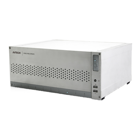
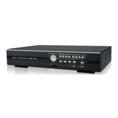
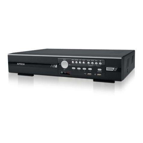
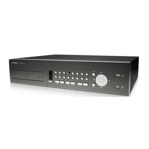
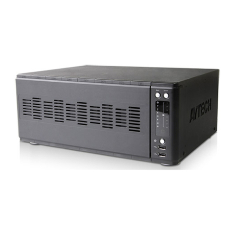
Avtech 715ZC User manual

207Z
715ZC, 717ZC / 715ZD, 717ZD / 715Z, 715Z_V1.7
HIGH-END SERIES
The image shown above may differ from he ac ual produc appearance.

IMPORTANT SAFEGUARD
Graphic Symbol Explanation
The ligh ning flash wi h arrowhead symbol, wi hin an equila eral riangle, is in ended o aler he user o he
presence of uninsula ed “dangerous vol age” wi hin he produc ’s enclosure ha may be of sufficien
magni ude o cons i u e a risk of elec ric shock o persons.
This exclama ion poin wi hin an equila eral riangle is in ended o aler he user o he presence of impor an
opera ing and main enance (servicing) ins ruc ions in he li era ure accompanying he appliance.
All lead-free produc s offered by he company comply wi h he requiremen s of he European law on he
Res ric ion of Hazardous Subs ances (RoHS) direc ive, which means our manufac ure processes and
produc s are s ric ly “lead-free” and wi hou he hazardous subs ances ci ed in he direc ive.
The crossed-ou wheeled bin mark symbolizes ha wi hin he European Union he produc mus be collec ed
separa ely a he produc end-of-life. This applies o your produc and any peripherals marked wi h his
symbol. Do no dispose of hese produc s as unsor ed municipal was e.
CE Mark
This appara us is manufac ured o comply wi h he radio in erference requiremen s.
Disclaimer
We reserve he righ o revise or remove any con en in his manual a any ime. We do no warran or assume any legal
liabili y or responsibili y for he accuracy, comple eness, or usefulness of his manual. The con en of his manual is subjec
o change wi hou no ice.
MPEG4 Licensing
THIS PRODUCT IS LICENSED UNDER THE MPEG-4 VISUAL PATENT PORTFOLIO LICENSE FOR THE PERSONAL
AND NON-COMMERCIAL USE OF A CONSUMER FOR (i) ENCODING VIDEO IN COMPLIANCE WITH THE MPEG-4
VISUAL STANDARD (“MPEG-4 VIDEO”) AND/OR (ii) DECODING MPEG-4 VIDEO THAT WAS ENCODED BY A
CONSUMER ENGAGED IN A PERSONAL AND NON-COMMERCIAL ACTIVITY AND/OR WAS OBTAINED FROM A
VIDEO PROVIDER LICENSED BY MPEG LA TO PROVIDE MPEG-4 VIDEO. NO LICENSE IS GRANTED OR SHALL BE
IMPLIED FOR ANY OTHER USE. ADDITIONAL INFORMATION INCLUDING THAT RELATING TO PROMOTIONAL
INTERNAL AND COMMERCIAL USES AND LICENSING MAY BE OBTAINED FROM MPEG LA, LLC. SEE
HTTP://WWW.MPEGLA.COM.
Version
Firmware Version: 1098-10-K4-04-AA-11 ; AP Version: 1062
For any changes of AP, please refer o your dis ribu or. The con en is his manual is subjec o change wi hou no ice.
CAUTION:
To reduce he risk of elec ric shock, do no expose his appara us o rain or mois ure.
Only opera e his appara us from he ype of power source indica ed on he label.
The company shall no be liable for any damages arising ou of any improper use,
even if we have been advised of he possibili y of such damages.
C
CA
AU
UT
TI
IO
ON
N
R
RI
IS
SK
K
O
OF
F
E
EL
LE
EC
CT
TR
RI
IC
C
S
SH
HO
OC
CK
K

TABLE OF CONTENTS
1. OVERVIEW ........................................................................................................................................ 1
1.1 Produc Descrip ion................................................................................................................................................ 1
1.2 Fea ures ................................................................................................................................................................. 1
Cover Recording .................................................................................................................................................. 1
1.3 Specifica ion ........................................................................................................................................................... 2
1.4 Package Con en s.................................................................................................................................................. 3
2. FRONT AND REAR PANELS ............................................................................................................ 4
2.1 Fron Panels........................................................................................................................................................... 4
2.2 Rear Panels ........................................................................................................................................................... 6
3. SETUP AND CONNECTIONS............................................................................................................ 8
3.1 Ins all HDD ............................................................................................................................................................. 8
3.2 Camera Connec ion ............................................................................................................................................... 8
3.2.1 Normal Camera Connec ion......................................................................................................................... 8
3.2.2 PTZ Camera Connec ion ............................................................................................................................. 8
3.3 Ex ernal Device Connec ions (Op ional)................................................................................................................. 9
3.3.1 VGA Conver er............................................................................................................................................. 9
3.3.2 Independen Disk Array................................................................................................................................ 9
3.4 Power Se up......................................................................................................................................................... 10
3.5 Da e and Time Se ing.......................................................................................................................................... 10
3.6 LAN or In erne Se up........................................................................................................................................... 10
3.6.1 STATIC IP .................................................................................................................................................. 10
3.6.2 DDNS Apply ............................................................................................................................................... 11
3.6.3 Dynamic IP - PPPOE ............................................................................................................................. 14
3.6.4 Dynamic IP - DHCP ............................................................................................................................... 15
3.7 Password and User Name Se ing ....................................................................................................................... 16
3.7.1 DVR Password Se ing............................................................................................................................... 16
3.7.2 Remo e Login Password and User Name Se ing...................................................................................... 17
3.8 Sys em Diagram................................................................................................................................................... 17
4. BASIC OPERATION ........................................................................................................................ 18
4.1 Recording............................................................................................................................................................. 18
4.2 Playback............................................................................................................................................................... 19
5. MAIN MENU..................................................................................................................................... 21
5.1 Menu Tree ............................................................................................................................................................ 21
6. MENU FUNCTION ........................................................................................................................... 22
6.1 Record.................................................................................................................................................................. 22
6.2 Timer .................................................................................................................................................................... 24
6.3 Da e...................................................................................................................................................................... 25
6.4 Advance ............................................................................................................................................................... 26
6.4.1 Camera ...................................................................................................................................................... 26
6.4.2 De ec ion.................................................................................................................................................... 27
(1 Detection Setup .................................................................................................................................... 27
(2 Detection Timer .................................................................................................................................... 29
6.4.3 Display ....................................................................................................................................................... 29
6.4.4 Aler ............................................................................................................................................................ 31
6.4.5 Remo e ...................................................................................................................................................... 32
6.4.6 Sys em ....................................................................................................................................................... 33
6.4.7 Ne work...................................................................................................................................................... 34
6.4.8 Backup ....................................................................................................................................................... 36
6.4.9 HDD Info .................................................................................................................................................... 38
6.4.10 Even Log................................................................................................................................................. 39
6.5 Search.................................................................................................................................................................. 39
6.6 Addi ional Opera ion............................................................................................................................................. 42
6.6.1 Key Lock and Unlock ................................................................................................................................. 42
6.6.2 Swi ch NTSC / PAL Sys em ....................................................................................................................... 42
6.6.3 Upgrade ..................................................................................................................................................... 42
(1) Firmware / Mul ilanguage OSD Upgrade................................................................................................ 42
(2) AP and JAVA Sof ware Upgrade ............................................................................................................. 42
6.6.4 Audio Backup and Playback....................................................................................................................... 43
6.6.5 PTZ Camera Se up and Con rol................................................................................................................. 43
6.6.6 R.E.T.R. Se up ........................................................................................................................................... 43
7. LICENSED SOFTWARE AP ............................................................................................................ 45
7.1 Ins alla ion ............................................................................................................................................................ 45
7.2 Login Panel .......................................................................................................................................................... 45
7.3 Con rol Panel ....................................................................................................................................................... 47
7.3.1 DVR Con rol Panel..................................................................................................................................... 47
7.3.2 PTZ Camera Con rol Panel........................................................................................................................ 50
7.4 Playback Opera ion.............................................................................................................................................. 51
7.4.1 AP Playback Func ions: ............................................................................................................................. 51
7.4.2 Conver he recorded file o AVI forma ...................................................................................................... 52
7.5 Sys em Configura ion ........................................................................................................................................... 52
7.5.1 Ne work...................................................................................................................................................... 53
(1) DDNS ..................................................................................................................................................... 54
(2) Mail......................................................................................................................................................... 55
(3) FTP......................................................................................................................................................... 55
7.5.2 DVR ........................................................................................................................................................... 56
(1 Device.................................................................................................................................................... 56
(2 Detection ............................................................................................................................................... 57
(3 Network Backup ................................................................................................................................... 58
(4 Search List ............................................................................................................................................ 60
(5 Timer Record ........................................................................................................................................ 61
(6 Date........................................................................................................................................................ 61
(7 Record Setting ...................................................................................................................................... 62
7.5.3 Alarm.......................................................................................................................................................... 63
(1 Alarm List .............................................................................................................................................. 64
7.5.4 General ...................................................................................................................................................... 64
(1 Account ................................................................................................................................................. 65
(2 Online User Info.................................................................................................................................... 67
(3 File Path ................................................................................................................................................ 67
7.6 Opera ion via IE Browser ..................................................................................................................................... 68
8. TROUBLESHOOTING ..................................................................................................................... 70
8.1 FAQ ...................................................................................................................................................................... 70
8.2 Defaul Value........................................................................................................................................................ 71
APPENDIX 1 INSTALL HDD................................................................................................................ 72
APPENDIX 2 PIN CONFIGURATION................................................................................................... 73
APPENDIX 3 RS-232 PROTOCOL ...................................................................................................... 74
APPENDIX 4 COMPATIBLE USB FLASH DRIVE BRAND ................................................................. 75
APPENDIX 5 COMPATIBLE HDD BRAND.......................................................................................... 76
INDEX .................................................................................................................................................. 77

-1-
1. OVERVIEW
1.1 Product Description
Wi h he high s orage capaci y fea ure, his MPEG-4 DVR model is designed o accommoda e up o 3 HDDs, or
accommoda e 2 HDDs and connec 1 independen disk array depending on your needs. To quickly backup, a CD or DVD
wri er (op ional) and USB in erface are buil in for your choices excep for ne work backup. Remo e Even Trigger
Recording (R.E.T.R.) can be ac iva ed remo ely and any even recording will be saved in he specified pa h in your PC. An
IR ransmi er is also supplied for remo e con rol.
1.2 Features
MPEG4 DVR Technology
‧ Compression forma providing crys al clear images wi h real ime performance
Multiplex Operation
‧ Allow live display, record, playback, backup, and ne work opera ions a he same ime
Remote Independent Operation
‧ Allow you o individually see he live view of a single channel wi hou changing he main display se ing from AP side
Huge Storage Capacity
‧ Suppor up o 3 HDD accommoda ion, or 2 HDD accommoda ion + 1 independen disk array (op ional)
Free Upgrade to Advanced Functions
‧ Allow you o upgrade DVR func ions wi hou any charges
Long-Recording Hours
‧ 500GB can record more han 52 days (16CH, CIF Normal Quali y, 60IPS)
‧ 500GB can record more han 104 days (8CH, CIF Normal Quali y, 30IPS)
‧ Connec o Independen Disk Array (op ional) o have more s orage capaci y
Backup Function
‧ Suppor CD or DVD wri er backup (op ional), USB flash drive backup & ne work backup
‧ The backup file can be played direc ly in your PC via he supplied licensed AP, or via o her media players
(For example, Windows Media Player or RealPlayer) af er he file is conver ed o “AVI” forma
Remote Surveillance
‧ Suppor remo e surveillance up o 5 users simul aneously wi h licensed sof ware AP and IE browser
Intelligent Motion Trigger Recording
‧ R.E.T.R. (Remo e Even Trigger Recording)
‧ Wi h he advanced func ions of mo ion de ec ion, scheduled mo ion de ec ion recording (4 differen adjus able fac ors
for mo ion de ec ion sensi ivi y) and quick search, cus omized securi y environmen s are achieved
‧
Alarm rigger recording will send aler s wi h images o designa ed e-mails and he FTP address
‧ Suppor pre-alarm recording (8MB)
Covert Recording
‧ A mask replaces he live image wi h a blank screen and he moni or shows no hing, bu he recording is s ill on
A/V Support
‧
Suppor 4 audio-in, 2 audio-ou o record sounds
‧ Suppor VGA ou pu o moni or (op ional)
General
‧ Suppor mul i-language OSD
‧ Suppor IR remo e con rol
‧ Sys em au o recovery af er power reconnec ed
‧ Suppor IR remo e con rol, PTZ camera opera ions hrough RS-485, and PTZ Ho Poin func ion
‧ Suppor dayligh saving func ion
‧ Suppor manual / imer / mo ion / alarm / ne work recording
‧ Ensure he au hen ica ion of recorded images wi h Wa ermark func ion
‧ Suppor TCP/IP, PPPOE, DHCP and DDNS ne work connec ion

-2-
1.3 Specification
SPECIFICATION
*
8CH 16CH
Video Sys em NTSC / PAL (swi chable)
Video Compression Forma MPEG4
Video Inpu
(Composi e video signal 1 Vp-p 75Ω BNC) 8 Channels 16 Channels
Video Loop Ou pu
(Composi e video signal 1 Vp-p 75Ω BNC) 8 Channels 16 Channels
Video Ou pu Main Moni or Ou pu : Composi e video signal 1 Vp-p 75Ω BNC
Call Moni or Ou pu : Composi e video signal 1 Vp-p 75Ω BNC
Maximum Recording Ra e (Frame) 720×480 pixels wi h 60 IPS <NTSC>
720×576 pixels wi h 50 IPS <PAL>
720×480 pixels wi h 120 IPS <NTSC>
720×576 pixels wi h 100 IPS <PAL>
Maximum Recording Ra e (CIF) 352×240 pixels wi h 240 IPS <NTSC>
352×288 pixels wi h 200 IPS <PAL>
352×240 pixels wi h 480 IPS <NTSC>
352×288 pixels wi h 400 IPS <PAL>
Adjus able Recording Speed (Frame) 60, 30, 15, 7 IPS <NTSC>
50, 25, 12, 6 IPS <PAL>
120, 60, 30, 15 IPS <NTSC>
100, 50, 25, 12 IPS <PAL>
Adjus able Recording Speed (CIF) 240, 120, 60, 30 IPS <NTSC>
200, 100, 50, 25 IPS <PAL>
480, 240, 120, 60 IPS <NTSC>
400, 200, 100, 50 IPS <PAL>
Mul i-language OSD Yes
Image Quali y Se ing Bes , High, Normal, and Basic
Hard Disk S orage
(IDE ype, ATA66) (Over 500GB)
Accommoda e 3 HDDs*, or 2 HDDs plus 1 independen disk array*
* HDDs and disk arrays are op ional.
HDD Quick Cleaning Quick clean up he “index sys em” of he recorded files
(500GB under 2 seconds)
Recording Mode Manual / Timer / Mo ion / Alarm / Remo e
Wa ermark YES
Refresh Ra e 240 IPS for NTSC
200 IPS for PAL
480 IPS for NTSC
400 IPS for PAL
Mul iplex Opera ion Live display, record, playback, backup and ne work
Remo e Independen Opera ion YES
Audio I/O 4 audio inpu s, 2 audio ou pu s (Mono)
R.E.T.R. (Remo e Even Trigger Recording) YES
Mo ion De ec ion Area 16 × 12 grids per camera for all channels
Mo ion De ec ion Sensi ivi y 4 adjus able variables wi h precise calcula ion for mo ion de ec ion
Pre-alarm Recording Yes (8 MB)
Backup Device
1. USB flash drive
2. Ne work
3. CD or DVD wri er (optional)
USB In erface Fron panel * 1, back panel * 1
Web Transmi ing Compression Forma Mo ion JEPG
Ne work Independen YES
E herne 10/100 Base-T. Suppor remo e con rol and live view via E herne
Web In erface Suppor licensed sof ware AP and IE browser
Remo e Alarm No ifica ion Email images, and upload images o FTP si e’s specific accoun
Ne work Pro ocol TCP/IP, PPPoE, DHCP and DDNS
IR Remo e Con rol YES
PTZ Con rol Suppor PELCO-D pro ocol
*
The specifica ions are subjec o change wi hou no ice.

-3-
SPECIFICATION
*
8CH 16CH
Dwell Time (Sequen ial Channel Swi ch) Programmable wi h adjus able dwell ime (2, 4, 8, 16 sec.)
Alarm I/O 8 inpu s, 1 ou pu 16 inpu s, 1 ou pu
Pic ure Zoom 2X digi al zoom
Key Lock YES
Video Loss De ec ion YES
Camera Ti le Suppor up o 6 le ers
Video Adjus able Hue / Color / Con ras / Brigh ness
Da e Display Forma YY/MM/DD, DD/MM/YY, MM/DD/YY, and Off
Dayligh Saving YES
Power Source DC 19V
Power Consump ion <64 W
Opera ing Tempera ure 10℃ ~ 40℃ (50℉~104℉)
Dimensions (mm) 432mm (W) × 90mm (H) × 326mm (D)
Sys em Recovery Sys em au o recovery af er power reconnec ed
Op ional Peripherals Independen disk array, VGA conver er
1.4 Package Contents
ITEMS QTY
Digi al Video Recorder (DVR) 1
Adap er and Power Cord 1
Screws 12
DSUB PIN Connec or 1
HDD Da a BUS Clip 1
IR Transmi er and IR Receiver Line (1.5m) 1
Manual 1
Quick Guide 1
CD or DVD disk (op ional) 1
Licensed Sof ware AP 1
*
The specifica ions are subjec o change wi hou no ice.

FRONT AND REAR PANELS
-4-
2. FRONT AND REAR PANELS
2.1 Front Panels
‧ 8CH
‧ 16CH
1) LED Indica ion
The following LEDs will be on when:
POWER: DVR is powered on.
STANDBY: DVR is powered off normally ill he nex ime DVR is powered on.
HDD: HDD is reading or under recording.
HDD Full: HDD is full.
ALARM: The alarm is riggered.
TIMER: Timer recording is enabled.
PLAY: DVR is under playback s a us.
REC: DVR is under recording.
2) USB
To quickly backup or upgrade firmware/OSD, you can inser a compa ible USB flash drive in o his USB por . There is
ano her USB por a he rear panel.
Note: For the list of compatible USB flash drives, please refer to “APPENDIX 4 OMPATIBLE USB FLASH
DRIVE BRAND” at page 75.
3) EJECT
Press “EJECT” bu on o open / close he CD or DVD wri er (op ional).
4) MENU
Press “MENU” bu on o en er he main menu.
5) ENTER/SET
Press “ENTER” bu on o confirm he se ing.
Press “SET” o change he posi ion of he channel display. For de ails, please refer o “Posi ion of Channel Display” in
sec ion ”4.2 Playback” a page 19.

FRONT AND REAR PANELS
-5-
6) SLOW
Under he playback mode, press “SLOW” bu on o slowly play he file.
7) ZOOM
Press “ZOOM” bu on o enlarge he image of he selec ed channel (under he live mode).
8) / -
8CH: Press “ ” bu on o show he 4 / 8 / 9 channel display modes.
16CH: Press “ ” bu on o show he 4 / 8 / 9 / 16 channel display modes.
Press “-” bu on o change he se ing in he menu.
9) SEQ /+
Press “SEQ” bu on o ac iva e he call moni or func ion, and press again o qui .
Press ”+” bu on o change he se ing in he menu.
10) (Audio)
Press hese wo bu ons a he same ime o selec live or playback sounds of he 4 audio channels.
11) (PTZ)
Press hese wo bu ons a he same ime o en er / exi he PTZ con rol mode.
In he PTZ con rol mode:
Zoom in: Press "+" bu on ; Zoom ou : Press "-" bu on
Adjus PTZ angle: Press "UP”, “DOWN”, “LEFT” or “RIGHT" bu ons
12) 1 ~ 8 (for 8CH) or 1~16 (for 16CH)
Press one of he bu ons o selec he channel o display.
13) SEARCH
Press “SEARCH” bu on o en er he search menu.
14) REC
Press “REC” bu on o ac iva e manual recording.
15)
Press “PLAY” bu on o play he recorded video.
16) PAUSE/UP, REW/LEFT, FF/RIGHT, STOP/DOWN
Press one of hese four bu ons o move he cursor up/down/lef /righ .
Under he playback mode:
Press “ ” or “ ” bu on o pause / s op playback.
Press “ ” or “ ” bu on o fas rewind / forward.
17) POWER
Press “POWER” bu on long enough o urn on/off your DVR.
Note: Under the recording mode, please stop recording before turning off your DVR.
18) REC + ENTER
To lock keys and log in ano her user name, press “REC” + “ENTER” on he fron panel a he same ime.
19) POWER + or
To swi ch o NTSC / PAL sys em, press and hold (for NTSC) or (for PAL) firs , and hen press “POWER” un il
he moni or shows video images.
Note: Before switching the system, please shutdown your DVR first.

FRONT AND REAR PANELS
-6-
2.2 Rear Panels
‧ 8CH
DC 19V
INPUT
DISK ARRAY
LOOP
RS 485
INPUT
IR
INPUT INPUT
EXTERNAL I/O
USB
INPUT
LOOP
3
LOOP LOOP LOOP
INPUT
D / V LAN
INPUT
ACT.
LINK
INPUT
CALL
LOOP LOOP LOOP
MONITOR
31
2 4
1) 75Ω / HI-IMPEDANCE
When using LOOP func ion, please swi ch o HI-IMPEDANCE. O herwise, please swi ch o 75Ω.
2) LOOP / INPUT (For channel 1~8)
LOOP: Video ou pu connec or.
INPUT: Connec o video sources, such as cameras.
3) MONITOR
Connec o MAIN moni or.
4) CALL
Connec o CALL moni or o show he channel display one by one.
When any alarm is riggered, CALL moni or will show he image of he riggered channel for a period of ime.
5) Audio IN (4 audio-in)
Connec o audio sources, such as cameras equipped wi h he audio func ion.
When users s ar recording, he audio inpu will also be recorded.
6) Audio OUT (2 audio-ou )
Connec o a moni or or speaker wi h 1 mono audio ou pu .
7) DISK ARRAY
Connec o an independen disk array for ex ended s orage.
8) IR
Connec o he IR receiver for remo e con rol.
9) RS-485
Connec o ex ernal devices (such as PTZ camera) wi h RS485-A and RS485-B.
10) EXTERNAL I/O
Inser he supplied 25PIN DSUB o his por for connec ing ex ernal devices (ex ernal alarm, PTZ camera, e c).
For de ailed I/O por PIN configura ion, please refer o “APPENDIX 2 PIN CONFIGURATION” a page 73.
11) USB
To quickly backup or upgrade firmware/OSD, you can inser a compa ible USB flash drive in o his USB por . There is
ano her USB por a he fron panel.
Note: For the list of compatible USB flash drives, please refer to “APPENDIX 4 OMPATIBLE USB FLASH
DRIVE BRAND” at page 75.
12) D/V
Connec o a VGA conver er.
13) LINK ACT.
When your DVR is connec ed o he In erne , his LED will be on.
14) DC 19V
Connec o he supplied adap er.
1
2
3
4
5
6
12
10
11
13
14
3
7
9
8

FRONT AND REAR PANELS
-7-
‧ 16CH
D / V
DISK ARRAY IR
RS 485
EXTERNAL I/O
USB
LAN
LINK
ACT.
DC 19V
MONITOR
CALL
LOOP
INPUT
1 2 3 4 5 6 7 8 9 10 11 12 13 14 15 16
HI-IMPEDANCE
1 875Ω
HI-IMPEDANCE
916
75Ω
1) 75Ω / HI-IMPEDANCE
When using LOOP func ion, please swi ch o HI-IMPEDANCE. O herwise, please swi ch o 75Ω.
2) LOOP / INPUT (For channel 1~16)
LOOP: Video ou pu connec or.
INPUT: Connec o video sources, such as cameras.
3) MONITOR
Connec o MAIN moni or.
4) CALL
Connec o CALL moni or o show he channel display one by one.
When any alarm is riggered, CALL moni or will show he image of he riggered channel for a period of ime.
5) Audio IN (4 audio-in)
Connec o audio sources, such as cameras equipped wi h he audio func ion.
When users s ar recording, he audio inpu will also be recorded.
6) Audio OUT (2 audio-ou )
Connec o a moni or or speaker wi h 1 mono audio ou pu .
7) DISK ARRAY
Connec o an independen disk array for ex ended s orage.
8) IR
Connec o he IR receiver for remo e con rol.
9) RS-485
Connec o ex ernal devices (such as PTZ camera) wi h RS485-A and RS485-B.
10) EXTERNAL I/O
Inser he supplied 25PIN DSUB o his por for connec ing ex ernal devices (ex ernal alarm, PTZ camera, e c).
For de ailed I/O por PIN configura ion, please refer o “APPENDIX 2 PIN CONFIGURATION” a page 73.
11) USB
To quickly backup or upgrade firmware/OSD, you can inser a compa ible USB flash drive in o his USB por . There is
ano her USB por a he fron panel.
Note: For the list of compatible USB flash drives, please refer to “APPENDIX 4 OMPATIBLE USB FLASH
DRIVE BRAND” at page 75.
12) D/V
Connec o a VGA conver er.
13) LINK ACT.
When your DVR is connec ed o he In erne , his LED will be on.
14) DC 19V
Connec o he supplied adap er.
1
3
4
5
6
12
10
11
13
14
7
9
8
2

BASIC OPERATION
-8-
3. SETUP AND CONNECTIONS
3.1 Install HDD
The HDDs mus be ins alled before he DVR is urned on. For de ailed ins alla ion ins ruc ions, please refer o
sec ion "APPENDIX 1 INSTALL HDD" a page 72.
1) Loosen he screws of he DVR upper cover and open he upper cover.
2) Screw ou he HDD bracke .
3) Screw HDD on o he HDD bracke . (The PCB side of he HDD mus face upward.)
4) Screw he HDD bracke back o he DVR base.
5) Connec he HDD o he power connec or and IDE BUS (make sure o align he HDD precisely for pin connec ion).
6) Close he upper cover of he DVR and fas en all he screws you loosened previously.
3.2 Camera Connection
The cameras mus be connec ed and power-supplied before he DVR is urned on. For de ailed DVR video inpu /
ou pu por s, please refer o sec ion “2.2 Rear Panels” a page 6. For de ailed ex ernal I/O por descrip ion, please refer o
sec ion “APPENDIX 2 PIN CONFIGURATION” a page 73. For de ailed camera se up, please refer o i s own manual.
Note: When using LOOP function, set the impedance switch at your DVR rear panel to HI-IMPEDANCE to
decrease interferences. The default setting is 75Ω.
3.2.1 Normal Camera Connection
1) Connec he camera wi h indica ed power supply.
2) Connec he camera video ou pu o he DVR video inpu por wi h a coaxial cable or RCA line wi h BNC connec or.
For de ailed camera i le, ID, pro ocol and baud ra e se up, please refer o sec ion “6.4.5 Remo e” a page 32.
3.2.2 PTZ Camera Connection
1) Connec he PTZ camera wi h indica ed power supply.
2) Connec he PTZ camera video ou pu o he DVR video inpu por wi h a coaxial cable or RCA line wi h BNC
connec or.
3) Connec “RS485-A” line (brown color) o RS485-A por on he rear panel of he DVR. Connec “RS485-B” line (orange
color) o RS485-B por on he rear panel of he DVR.
Note: For detailed camera ID, protocol and baud rate setup at DVR side, please refer to section “6.4.5
Remote” at page 32. For detailed camera ID, protocol and baud rate setup at remote AP software side,
please refer to section “(1) Device” at page 56 (AP software system configuration). For detailed PTZ
control instructions, please refer to section “6.6.5 PTZ amera Setup and ontrol” at page “43”.

BASIC OPERATION
-9-
3.3 External Device Connections (Optional
3.3.1 VGA Converter
This op ional peripheral (VGA Conver er) allows your DVR o have VGA ou pu func ion. For he connec ion me hod,
please refer o he following figure as an example. For de ailed connec ion me hods, please refer o your VGA conver er
manual.
3.3.2 Independent Disk Array
For he connec ed IDA o be correc ly de ec ed by your DVR, please don’ ins all HDD in he “HDD3” posi ion. For
connec ion de ails, please refer o "APPENDIX 1 INSTALL HDD" a page 72.
1) Ins all HDDs: Ins all HDDs in he IDA. Please se he HDD o “Mas er” mode (do no use “Slave” mode). Af er all HDDs
are ins alled, please lock he HDD ray by using he HDD key supplied in he IDA package.
2) Connec all IDA wi h SCSI cables (hub IDA only):
Connec from one of he hree “DEVICE PORT” a one IDA rear panel o he hos por of ano her disk array.
One IDA (as he mas er layer) can connec up o 3 IDA as he second layer, and each IDA in he second layer can
respec ively connec up o 3 IDA as he hird layer. Please refer o he illus ra ion below for de ails.
Note: In order to accurately detect all the connected disk arrays, please make sure to turn on the power of
all the disk arrays after the connection is completed. The maximum layer number is 3, totally 13 IDA.
3) Connec he mas er IDA o your DVR wi h a SCSI Cable (IDE in erface): Connec he hos por of he mas er IDA o he
“DISK ARRAY” por of your DVR. Please refer o he illus ra ion below for de ails.

BASIC OPERATION
-10-
3.4 Power Setup
This device should be opera ed only wi h he ype of power source indica ed on he manufac urer’s label. Connec he
indica ed AC power cord o he power adap er, and plug in o an elec rical ou le . “POWER” LED will be on as red. Press
“POWER” bu on, and “POWER” LED will be on as green. I akes approxima ely 10 o 15 seconds o boo he sys em.
3.5 Date and Time Setting
Before opera ing your DVR, please se he da e and ime on your DVR firs .
You can use he following bu ons for menu se ing:
BUTTON FUNCTION
UP, DOWN, LEFT, RIGHT Move he cursor.
+ , - Choose numbers / selec ions.
ENTER Go o he submenu / confirm he selec ion.
MENU Go o he menu lis / confirm he change / exi he menu lis .
1) Da e and Sys em:
DATE
DATE 2006-AUG-28 18:30:00
FORMAT Y-M-D
DAYLIGHT SAVING ON
2) Dayligh Saving:
The menu pa h is as following: “MENU” → “DATE” → “DAYLIGHT SAVING”.
DAYLIGHT SAVING
START 4
TH
-SUN-MAR 24:00:00
END 4
TH
-SUN-OCT 24:00:00
ADJUST 01:00
Note: Please DO NOT change the date or time of your DVR after the recording function is activated.
Otherwise, the recorded data will be disordered and you will not be able to find the recorded file to
backup by time search. If users change the date or time accidentally when the recording function is
activated, it’s recommended to clear all HDD data, and start recording again.
Note: If the time and date settings return to their default values after the DVR is rebooted, please charge the
DVR for at least 24-48 straight hours. Please contact your local retailer if the situation still occurs.
3.6 LAN or Internet Setup
3.6.1 STATIC IP
1) Build a Local Area Ne work (LAN) be ween DVR and PC/NB wi h ne work cable:
Your NB/PC and DVR mus be under he same ne work domain o build he area ne work. Please change he IP
address of your PC/NB in o 192.168.1.X (X can be he number be ween 1~255, excep 10) and he subne mask in o
255.255.255.0 for communica e wi h he DVR.

BASIC OPERATION
-11-
Ins all he supplied AP sof ware on your NB/PC. Then, log in o he DVR wi h he supplied AP sof ware for he
following defaul DVR se ings.
‧ The DVR defaul IP address: 192.168.1.10
‧ The DVR defaul accoun / password: admin
‧ The DVR defaul por : 80
2) Se DVR ne work se ing in “SYSTEM CONFIG” “Ne work” of he supplied AP:
In he “SYSTEM CONFIG” “Ne work” of he supplied AP, selec he “Static IP” in “IP TYPE” sec ion. And hen
ype he “Server IP”, “Gateway”, “Net Mask” and “Web Port” (1~9999) informa ion ob ained from your ISP.
Press ”APPLY” bu on o confirm he se ing.
3) Login your DVR via an E herne or dial-up ne work.:
Af er se ing up he ne work informa ion of he DVR and connec i o he ne work, you can use he IP address / Por
/ Accoun / Password you jus en ered in he supplied AP sof ware o log in o your DVR remo ely.
Note: Before changing the network properties of your PC/NB, please write down the original network
properties in case you need to recover the properties later.
3.6.2 DDNS Apply
You need o apply a DDNS accoun before se ing PPPoE or DHCP connec ion. DDNS is a service for ransforming
he dynamic IP corresponding o a specific “Hos name”. For DDNS se up, please refer o he s eps below.
‧ Go o a websi e which provides free DDNS services and apply a “Hos name”.
For example, go o h p://www.dyndns.com.

BASIC OPERATION
-12-
‧ En er all he informa ion necessary for signing up an accoun according o he websi e ins ruc ions.
‧ Then, you will see he screen “Accoun Crea ed”, and Dyndns will email he ins ruc ions o your specified E-mail
address for enabling your accoun . You mus comple e he procedure according o he ins ruc ions in he mail. Tha is
o mus visi he confirma ion address wi hin 48 hours of he ime ha he e-mail was sen o comple e he accoun
crea ion process. Then, you will see “Accoun Confirmed”. Your accoun is crea ed successfully now.

BASIC OPERATION
-13-
‧ Log in wi h your accoun informa ion and click ”My Service”.
‧ Click ”Add Hos Services”.
‧ Click ”Add Dynamic DNS Hos ”.
‧ Fill in and choose he desired hos name.

BASIC OPERATION
-14-
‧ The hos name is crea ed. You will be connec ed o he corresponding IP address whenever you en er his hos name.
3.6.3 Dynamic IP -
--
- PPPOE
1) Build a Local Area Ne work (LAN) be ween DVR and PC/NB wi h ne work cable:
Your NB/PC and DVR mus be under he same ne work domain o build he area ne work. Please change he IP
address of your PC/NB in o 192.168.1.X (X can be he number be ween 1~255, excep 10) and he subne mask in o
255.255.255.0 for communica e wi h he DVR.
Ins all he supplied AP sof ware on your NB/PC. And hen login he DVR wi h he supplied AP sof ware for he
following defaul DVR se ings.
‧ The DVR defaul IP address: 192.168.1.10
‧ The DVR defaul accoun / password: admin
‧ The DVR defaul por : 80
2) Se DVR ne work se ing in “SYSTEM CONFIG” “Ne work” of he supplied AP:
In he “SYSTEM CONFIG” “Ne work” of he supplied AP, selec he “PPPOE” in “IP TYPE” sec ion. And hen ype
he “User Name” and “Password” ob ained from your ISP. Press ”APPLY” bu on o confirm he se ing.
3) Se DVR DDNS se ing in he “SYSTEM CONFIG” “NETWORK” “DDNS” of he supplied AP sof ware:
‧ DDNS: Choose “Enable”.
‧ User Name: Type your DDNS account.
‧ Password: Type your DDNS password.
‧ Domain: Type he “Host Name” you applied previously (EX: securi yany ime.dyndns.org).
‧ Sys em Name: Choose he DDNS server where you applied he domain name (EX: dyndns).
Af er se ing, please press “APPLY” bu on o confirm and finish he se ing.

BASIC OPERATION
-15-
4) Login your DVR via an E herne or dial-up ne work.:
Af er se ing up he ne work informa ion of he DVR and connec i o he ne work, you can ype DDNS hos name,
defaul user name and password in he supplied AP sof ware login page o log in o your DVR remo ely.
3.6.4 Dynamic IP -
--
- DHCP
Ge a rou er and use he defaul IP address provided by your rou er o login o he rou er. Enable he DHCP server
and se he s ar ing IP address, ending IP address and lease ime. The DHCP Server of he rou er will au oma ically
alloca e an unused IP address from he IP address pool o he reques ing compu er.
1) Build a Local Area Ne work (LAN) be ween DVR and PC/NB wi h ne work cable:
Your NB/PC and DVR mus be under he same ne work domain o build he area ne work. Please change he IP
address of your PC/NB in o 192.168.1.X (X can be he number be ween 1~255, excep 10) and he subne mask in o
255.255.255.0 for communica e wi h he DVR.
Ins all he supplied AP sof ware on your NB/PC. And hen login he DVR wi h he supplied AP sof ware for he
following defaul DVR se ings.
‧ The DVR defaul IP address: 192.168.1.10
‧ The DVR defaul accoun / password: admin
‧ The DVR defaul por : 80
2) Se DVR ne work se ing in “SYSTEM CONFIG” “Ne work” of he supplied AP:
In he “SYSTEM CONFIG” “Ne work” of he supplied AP, selec he “DHCP” in “IP TYPE” sec ion. Then
press ”APPLY” bu on o confirm he se ing.
Se DVR DDNS se ing in he “SYSTEM CONFIG” “Ne work” “DDNS” of he supplied AP sof ware.
‧ DDNS: Choose “Enable”.
‧ User Name: Type your DDNS account.
‧ Password: Type your DDNS password.
‧ Domain: Type he “Host Name” you applied previously (EX: securi yany ime.dyndns.org).
‧ Sys em Name: Choose he DDNS server where you applied he domain name (EX: dyndns).

BASIC OPERATION
-16-
3) Af er se ing, please press “APPLY” bu on o confirm and finish he se ing.
4) Login your DVR via an E herne or dial-up ne work:
Af er se ing up he ne work informa ion of he DVR and connec i o he ne work, you can ype DDNS hos name
and defaul user name and password in he supplied AP sof ware login page o log in o your DVR remo ely.
3.7 Password and User Name Setting
3.7.1 DVR Password Setting
You can use he following bu ons for menu se ing:
BUTTON FUNCTION
UP, DOWN, LEFT, RIGHT Move he cursor.
+ , - Choose numbers / selec ions.
ENTER Go o he submenu / confirm he selec ion.
MENU Go o he menu lis / confirm he change / exi he menu lis .
1) Admin password:
Password for supervisor, allow all he se up of DVR.
2) Gues password:
Only allow viewing he live s reaming video and sequencing display, shif ing he channel display, and locking keys.
Note: The menu path is as following: MENU → ADVAN E → SYSTEM → PASSWORD → SETUP → ADMIN
PASSWORD / GUEST PASSWORD.
This manual suits for next models
5
Table of contents
Other Avtech DVR manuals

Avtech
Avtech DR163Z User manual

Avtech
Avtech KPD616 User manual

Avtech
Avtech MPEG4 User manual

Avtech
Avtech PVR16 User manual

Avtech
Avtech avh-312 User manual

Avtech
Avtech AVC796 User manual

Avtech
Avtech AVC708H User manual

Avtech
Avtech H.265 XVR Series User manual

Avtech
Avtech DG10 Series User manual

Avtech
Avtech DG1015 User manual

Avtech
Avtech AVH304 User manual

Avtech
Avtech 616 User manual

Avtech
Avtech DG1648 User manual

Avtech
Avtech AVC799B User manual

Avtech
Avtech AVC700 User manual

Avtech
Avtech AVC-793 User manual

Avtech
Avtech AVL683 User manual

Avtech
Avtech MDR688ZB User manual

Avtech
Avtech DG1648 Assembly instructions

Avtech
Avtech DGD8132 User manual