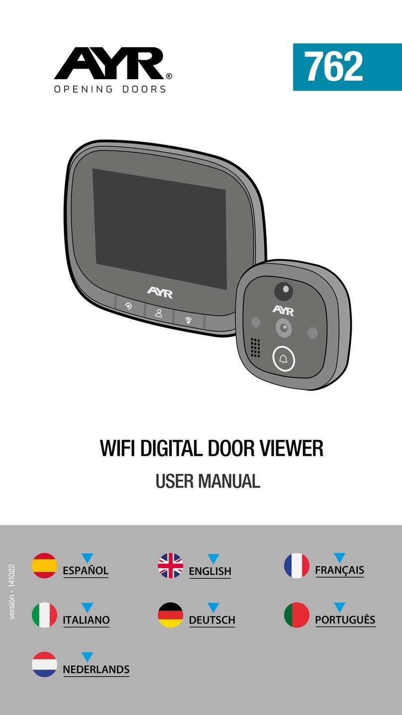
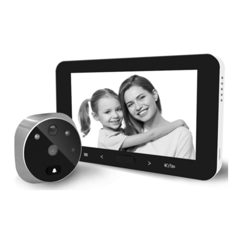
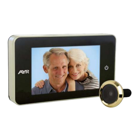
AYR 758 User manual

758
DIGITAL DOOR VIEWER with ALARM
USER MANUAL
Versión del manual - 141221

3
WARNING!
DO NOT PUT THE BATTERIES
until the peephole is
fully installed at the door

4
Correct assembly
When tting the door bell camera, rst unscrew the camera barrel and then
peel off the 3M sticker from the back of the camera (Fig. 1).
Stick the camera to the outside of the door making sure the door bell is at
the bottom (Fig. 2).
Incorrect assembly
DO NOT t the door bell camera without sticking to the door using the 3M
sticker. This would cause the door bell to rotate and will damage the cables
and may cause the unit to fail (Fig. 3).
WARNING!
Make sure you assemble the doorbell camera
carefully.
IF THE CAMERA WIRE IS PULLED OR FOLDED,
this could damage the product.

5
1. Package list ���������������������������������������������������������������������� 5
2. Installation instructions ���������������������������������������������� 6
3.Installation and replacement of batteries ����������� 7
4. Button functions ��������������������������������������������������������� 8,9
5. Memory Card Installation ���������������������������������������� 10
6. Adjust settings ������������������������������������������������������������� 10
7. Vibration alarm function �������������������������������������������� 13
8. Quick guide ������������������������������������������������������������������ 14
9. Specifications���������������������������������������������������������������� 15
Index
USER MANUAL
WARNING:
1. Please READ THIS USER MANUAL CAREFULLY before
using the product.
2. CONSERVEZ et utilisez ce manuel.
3. TO AVOID DAMAGE to the product or injury to the user,
never attempt to repair or change the product or its acces-
sories by yourself.
4. BATTERIES: Any abandoned batteries should be dispo-
sed according to local environment protection rules and
regulations.
5. ANY ACCIDENTAL FACTOR such as being struck by
lightning or any incorrect operation could cause a memory
loss on the SD card. Keeping copies of the videos is stron-
gly recommended in case of memory loss. We are not res-
ponsible for any loss of data.mations.

6
1 LCD Screen
1 ixing screw
4 x AAA batteries
1 Holding plate
1 Camera
3 Locking barrel
1 Tightening tool
1
2
3
4
5
6
7
1. Package list:
2
7
4
1
3
56
Before install:
Before installation, unscrew the re-
tainer plate from the bottom of the
visor and remove the adhesive pro-
tector.
Make sure that the thickness of the
door where the peephole will be ins-
talled is appropriate.
Please note that for some doors the
thickness in the center may be diffe-
rent than other parts.

7
Replace the existing door viewer or drill a 14mm hole in the door at the
required height. Peel off the 3M sticker top layer and then insert the ca-
mera from the outside . Ensure the door bell button is under the camera
and adjust the camera vertically to the ground(FIG.1)
Warning: It is very important to peel off the label so that the camera is
perfectly attached to the door(FIG. 1).
1.
Peel off the 3M sticker top layer on the holding plate and fit the holding
plate over the end of the camera wires on to the back of the door. Make
sure the arrow on the holding plate points upwards. Then screw up the
locking barrel on to the back of the camera.This will hold the plate to
the door(FIG.2)
2.
When inserting the camera wire into the socket ,ensure you match the
connectors correctly.(FIG. 3) If inserted incorrectly, this can damage the
camera cables. The excessive wire should be gently placed into the
groove at the back of the screen.
Warning: it is very important that the connector is perfectly connected
and in the position indicated.
3.
2. Installation instructions
FIG. 1 FIG. 2
FIG. 3

8
Hook the screen over the bracket at the top of the holding plate and
secure with one small screw through the hole at the bottom of the
screen.(FIG. 4).
4.
FIG. 4
HANG
SCREW
DOOR
3.Installation and replacement of batteries:
1. Slide the lid upwards to open, as shown in diagram.
2. Put in the batteries according to the “+” “-” sign on the lid.
3. Take the reverse steps to close the lid.
WARNING:
1. DO NOT force when opening and closing the lid to avoid lid
damage.
2. DO NOT press the lid to the opposite direction when opening to
avoid any lid damage.
3. When the low battery indicator is on, please replace all batteries to
avoid any damage to this product by battery weeping.
4. Use AAA, LR03 1.5V alkaline battery.
5. WARNING! DO NOT use rechargeable batteries.
8

9
4. Button functions:
6 SD card socket
1
2
3
4
5 camera data wire connector
menu
Scroll down
On / off
Scroll up Select les
Option conrmation
take photos
6
5
Nº
Alarm activation/deactivation
Basic function Other functions

Nº button multi functions
1
-In home page, press UP button to
enter picture browse mode;
-After enters picture browse mode,
press UP button to browse pictures
backwards;
-In setting mode, press Up button to
adjust the item you selected;
2
-In picture browse mode, press
Down button to browse pictures
onwards;
-In setting mode, press Down button
to adjust the item you selected;
-In home page, press Down button
to take picture.
3
-Press Menu button to enter menu
page;
-When deleting pictures, press
Menu button you can then choose
to delete the current photo;
-In picture browse and setting mode,
press and hold the menu button to
exit the current page.
4-After installing new batteries, press
and hold power button to start.
10

11
3
2
1
Camera front view Camera side view
1 camera 2 Doorbell 3 Data cable
5. Memory Card Installation
-Max. 8GB TF card can be used, over HDSC Class 6 is suggested
-Before inserting the TF card, make sure the metal cover above the TF
card socket is pushed towards the OPEN mark.(OPEN)
-Lift and open the upper of the metal cover and insert TF card into the
metal cover Then replace the metal cover and push back to LOCK mark
(LOCK).
-If the card cannot be read, format it to FAT 32 from a computer.
6. Adjust settings
Selection of recorded images:
-The default store is local file. (Capacity = 26 photos)
-In the setting menu you can select where to save the images, in internal
memory or on SD card (not included)
-To do this, select settings menu and tap below until you reach the disk
icon, tap to select the peephole or card, and then press the button.
until you exit the main screen.
512 MB

12
System settings:
-Under normal mode, press to enter setting mode.
-Then you should see the below setting mode page.
-Press to find different settings.
Time--Date--Ringtone--Volume--Auto power-off time--Save file in
-Press to change the settings.
-In TIME/DATE setting, press will increase the current number;
Holding the button down will accelerate the adjustment.
-After the setting is changed, the system will automatically save the
result and exit the setting page in a few seconds.
-If you need to exit the setting page, press and hold
Time setting
Ringtone setting
Auto power-o
setting
Date setting
Volume setting
0: silent mode
3: max volume
Save le in
* local le
* TF card

13
Instructions for use:
To observe outdoors:
-Under normal mode, you can observe outdoors once you press the
power button .
Visitors:
-When visitors press the door bell, the bell will ring inside the room. The
screen will automatically turn on showing the image of outside. It will
automatically power off once the set time is reached.
-Under normal mode, press will take a picture of outdoors and save it
automatically.
-Also as the door bell is pressed, the camera will automatically take a
photo of the visitors and the photo will be stored in the set file in case the
host is out, so as to check the visitors’ identity afterwards or to use the
information for security purposes..
Replay and delete of the photos:
-Under normal mode, press to replay photos
-When you browse the photos, press or to choose photos
-When you check the photos, press button to choose to delete the current
photo. After a short press on the button, you will see trash icon
-Press to confirm to delete.
01/2 21 2/22 09 26
Current photo number/
total number
month/date shooting time

14
7. Vibration alarm function
1- The vibration alarm function is shut by default at the factory. The
vibration alarm function needs to be started by pressing the button
for 3 seconds when display turns on.
2- The buzzer emits three beeps and a vibration alarm icon appears in
the lower right corner of the display.
3- To shut the vibration alarm function needs to press the button for
3 seconds when the display turns on. The buzzer emits a long “drip”
sound, the vibration alarm icon disappears, which indicates the
vibration alarm function shuts.
4- When the vibration alarm function starts, once the Digital Door Viewer
detects the vibration, it will trigger an alarm. After 10 seconds, the display
automatically turns on, take a photo, emits a continuous alarm sound
“Drip”, and a red alarm iconppears in the lower right corner of the display.
5-After 10 seconds the Digital Door Viewer stops the alarm, shuts down
and continues keeping the vibration alarm monitoring state.
6- After the vibration alarm is triggered, the owner can cancel the alarm
at any time by short pressing the power button of the display.en appuyant
sur le bouton ON .

15
8. Quick guide:
Discover on
Take photo
on scroll
See photos
Delete photos
select
Set options
1. on 2.scroll
3. select 4. access
5. select 6. conrm
1. on 2. acces
3. select 4. acces
5. select 6. conrm
on take photo
on off
Alarm press
3 seg.
press
3 seg.
++
,
,

16
9. Specifications
Model: 7040M
Door thickness: 38~110mm
Door barrel diameter: 14-26mm
Camera: 0.3 Mega pixels
LCD Screen: 4.0”TFT
Resolution: QVGA (480x320)
Power: 4 AAA, LR03 1.5V alkaline battery
Local memory storage: Approx 26 photos (The amount could differ de-
pending on the type of environment the camera is situated in exterior )
Card type: Micro SDcard (TF), max 8GB. NOT include TF card. This
should be purchased by user separately.
Photo volume for 1GB: 2000pc (lab condition, the actual volume could
differ under different circumstances)
Size: 139(w) 77(H) 15.8(D)mm
Weight:185g
Alarm: 90 dB

17
IT
ATTENZIONE!
NON INSERIRE LE PILE
fino a quando lo spioncino non
sia completamente installato
sulla porta.

18
MONTAGGIO CORRETTO
Per smontare la telecamera-campanello, è necessario innanzitutto svitare il
tubo di ssaggio alla porta ed estrarre la carta protettiva dell’adesivo 3M dalla
parte posteriore (FIG.1).
In seguito, appoggiare la telecamera sulla parte esterna della porta veri-
cando che sia ben ssa in posizione verticale e con il campanello nella parte
inferiore (FIG.2).
MONTAGGIO INCORRETTO
Non montare la telecamera sulla porta senza averla attaccata con l’etichetta
adesiva 3M. Potrebbe danneggiare il cavo che in questo modo avrebbe spa-
zio per avvolgersi liberamente (FIG.3).
ATTENZIONE!
Verificare che la telecamera sia montata corretta-
mente.
NON PIEGARE NÉ TIRARE IL CAVO
della telecamera altrimenti potrebbe rompersi.

19
IT
1. Contenuto ����������������������������������������������������������������������� 20
2. Spioncino: installazione sulla porta ������������������ 21
3. Batteria: installazione e sostituzione ����������������� 22
4. Funzioni dei tasti �������������������������������������������������������� 23
5. Installazione scheda di memoria ������������������������� 25
6. Configurazione dello spioncino ��������������������������� 25
7. Funzione dell’allarme������������������������������������������������� 28
8. Guida rapida ��������������������������������������������������������������� 29
9. Specifiche tecniche ���������������������������������������������������� 30
Indice
MANUALE UTENTE
WARNING:
1. LEGGERE questo manuale prima di utilizzare il prodotto.
2. CONSERVARE e utilizzare questo manuale.
3. NON SMONTARE l’articolo. In questo caso la garanzia non
sarà valida.
4. BATTERIE: smaltire correttamente le pile usate-. Non
bruciarle né sotterrarle. Non ingerirle. Non ricaricarle.
Tenerle lontano dalla portata dei bambini.
5. NON TAGLIARE la confezione delle pile per evitare
di rovinarle.
6.QUALSIASI FATTORE ACCIDENTALE come una
scossa elettrica o un’installazione o uso inadeguati po-
trebbero causare la perdita della memoria nella scheda
SD. Effettuare copie di questa informazione. Non saremo res-
ponsabili di questo tipo di perdite.

20
1 Spioncino LCD
1 Vite di fissaggio
4 x Pile AAA
1 Piastra di supporto
1 Telecamera
3 Tubi di fissaggio
1 Chiave di serraggio
1
2
3
4
5
6
7
1. Package list:
2
7
4
1
3
56
Prima dell’installazione:
Prima dell’installazione, svitare la piastra di
sostegno dalla parte inferiore dello spioncino
ed estrarre l’adesivo protettivo.
Vericare che lo spessore della porta
dove si monta lo spioncino sia adeguato.
Tener presente che in alcune porte lo
spessore nella parte centrale è diverso
dal resto della porta.
This manual suits for next models
1
Table of contents
Languages:
Other AYR Intercom System manuals