manuals.online logo
Brands
  1. Home
  2. •
  3. Brands
  4. •
  5. B.E.G.
  6. •
  7. Security Sensor
  8. •
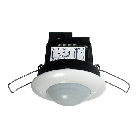
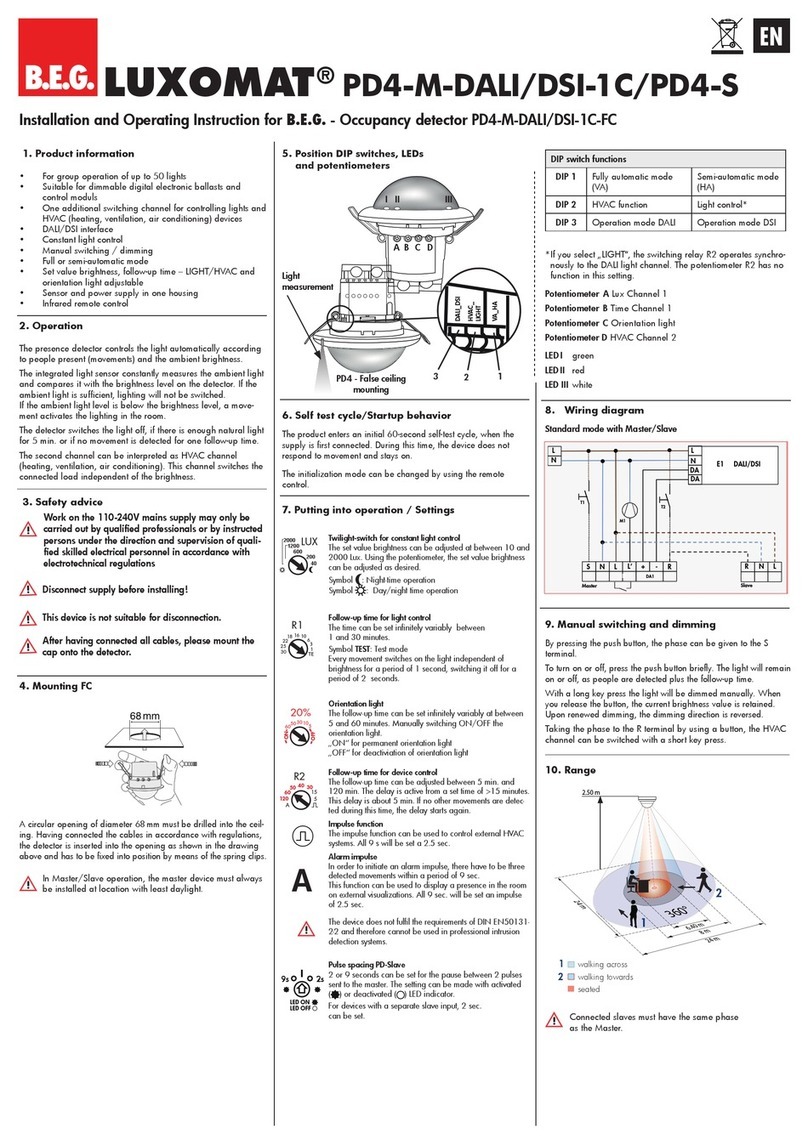
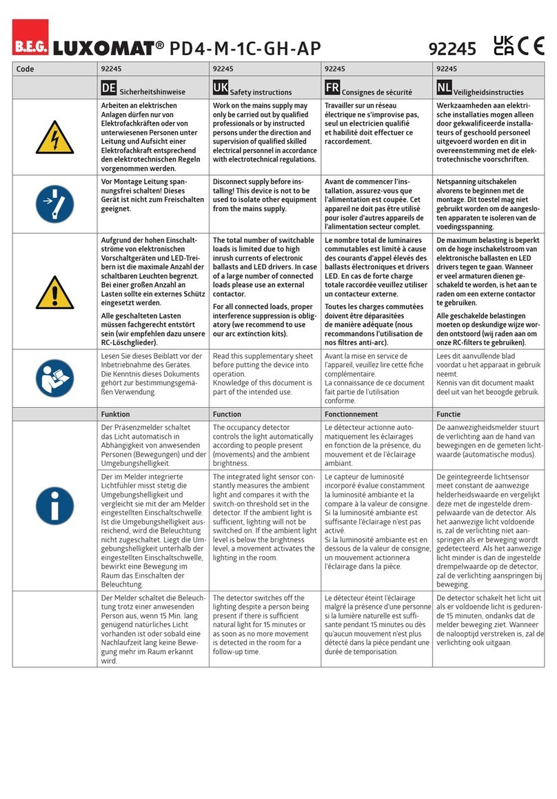
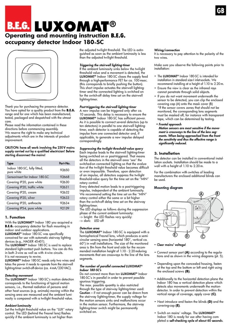
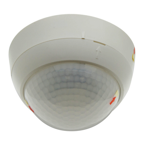
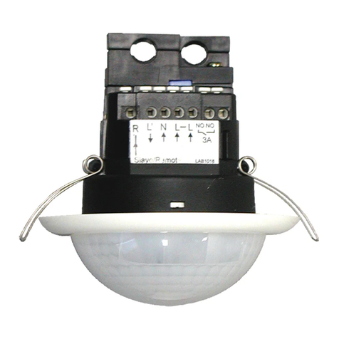
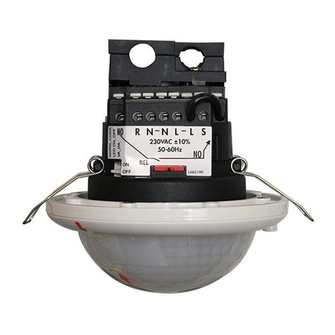
  9. B.E.G. LUXOMAT PD4-M-3C-TRIO-SM User guide

B.E.G. LUXOMAT PD4-M-3C-TRIO-SM User guide

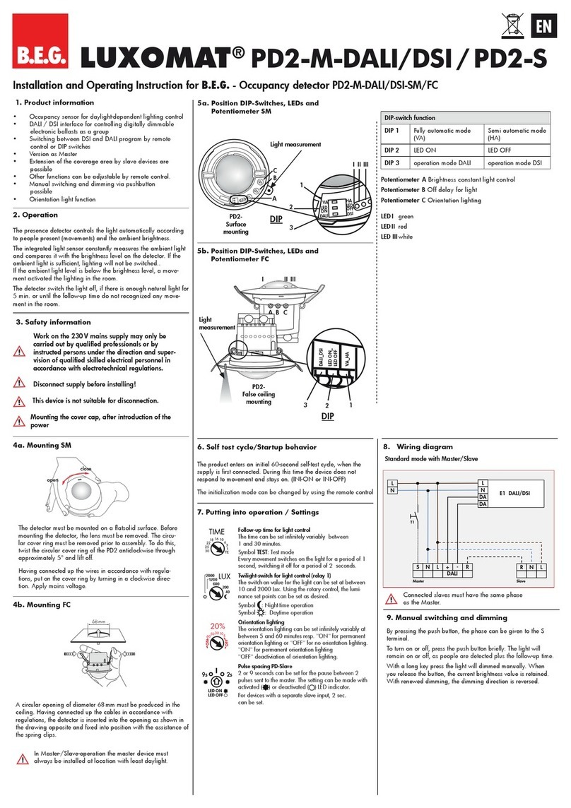
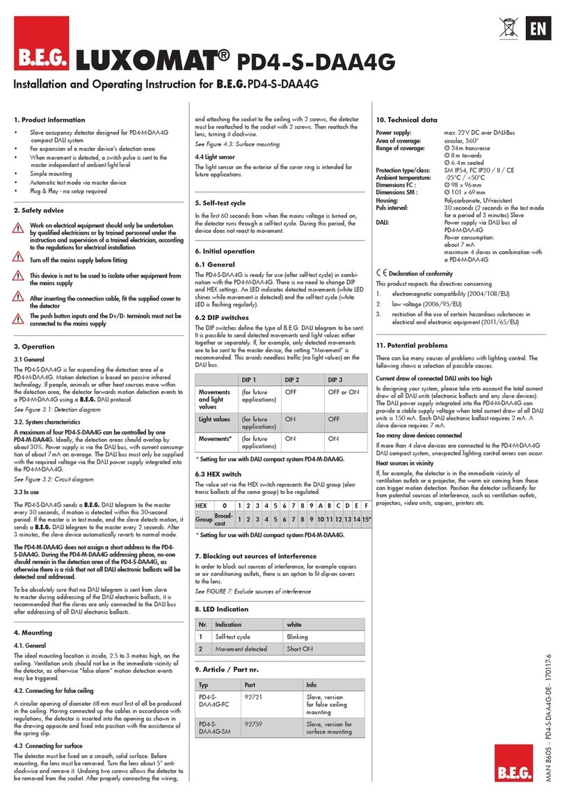
6. Putting into operation / Settings
Self test cycle
After an initial 60-second self-test cycle, the LUXOMAT®PD4-M-3C-TRIO
is ready for operation.
Follow-up time for light control 3 (see point 7)
The time can be set infinitely variably at between
1 and 60 minutes. The time-setting is valid for all 3 channels
of the PD4-M-3C-TRIO.
Symbol TEST: Test mode
Every movement switches on the light for a period of 2
seconds, switching it off for a period of 2 seconds after that
regardless of the level of brightness.
Twilight-switch for light control (Channel 1) - potentiometer
1 (see point 7)
The switch-on value for the light can be set at between 40
and 1200 Lux. Using the rotary control, the luminance set
points can be set as desired.
Symbol : Night operation
Symbol : Day/Night operation
Twilight-switch for light control (Channel 2) - potentiometer
3 (see point 7)
Settings identically equal to channel 1
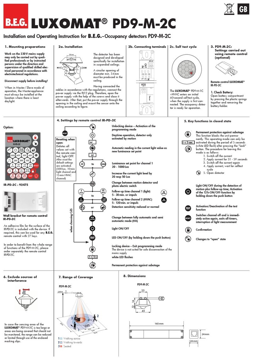
Installation and Operating Instruction for B.E.G. -Occupancy detectors PD4-M-3C-TRIO-SM/-FC
A circular opening
of diameter 100 mm
must be produced in
the ceiling.
Having connected
up the cables in
accordance with
regulations, the
detector is inserted
into the opening as
shown and fixed
into position with
the retaining bracket
using screws.
A/B Light sensor 1 / light sensor 2
1 LED red OFF function
2 LED green too light/too dark CDS 1
3 LED white semi-automatic switching channel 1
4 LED white semi-automatic switching channel 2
5 LED green too light/too dark CDS 2
6 LED red motion indicator/walking test
ADIP 1 HA / A
BDIP 2 Ini OFF/ON
Lamps at start-up OFF/ON
CDIP 3 RESET
2a.
Installation of the LUXOMAT
®
PD4-M-3C-TRIO-SM
2b.
Installation of the
LUXOMAT®
PD4-M-3C-TRIO-FC
3. Hardware configuration
Position of light sensors and LEDs
7. Position of potentiometer and DIP switch
The detector must be installed on a solid and
level surface. The circular cover ring must be
removed prior to assembly. To do this, twist the
lens (C) anticlockwise by approximately 5° and
lift off.
Having connected up the wires in accordance with
regulations, secure the detector with 2 screws.
After installation replace the lens and lock (turn
clockwise). Mains to be connected
.
4. Putting into operation of
the remote control IR-PD4-
TRIO SWI (optional)
Check Battery:
Open battery com-
partment by pressing
the plastic springs
together and remov-
ing the battery-holder.
Caution: Settings with remote control su-
persede the settings by potentiometers.
5. Light measuring
In order to calculate a switching
threshold, there is a five-minute light
measurement. For his the detector
switches off all channels and turns
them on for five minutes afterward.
This measurement is made if:
• a new brightness value is changed
with the poti
• a new nominal value is set by use of
the remote control (finish setting up
with CLOSE switch)
The measurement is not done during
the activated test function.
Unlocking the device interrupts the
light measuring.
LUXOMAT®PD4-M-3C-TRIO
1. Mounting preparations
Work on the 230V mains supply
may only be carried out by quali-
fied professionals or by instructed
persons under the direction and
supervision of qualified skilled elec-
trical personnel in accordance with
electrotechnical regulations.
Disconnect supply before installing!
When in Master/Slave mode of
operation, the Master-appliance
must always be installed at the
location where there is least
daylight.
Option:
Wall bracket for remote
control
IR-PD4-TRIO SWI
6
5
4
A
3
2
1
B
A4 5 1 3 2 6
B
DIP
321 1 2 3
GB
45
30
15
5
1
TEST
60
1200
600
200
40
80 - 90 mm
100 mm
close
open C
31
2
C BA
Unlocking device
Lock device
8. Settings by remote control (Settings relay channel 1, 2, 3)
to
Step function
LED display ON/OFF
Unlocking
If device is unlocked, setting can be done for all channels.
Directly after unlocking, channel 1 is always chosen at first
Automatic reading of the actual light level channel 1+2
• Switching threshold, if light OFF
• Shutdown threshold, if light ON
Step function: increase the current light level by 20 Lux
Resetting when open
The potentiometers are released for settings
Semi automatic for the selected channel
(Switching channel 1+2 can be activated only together)
Fully automatic for the selected channel
(Switching channel 1+2 can be activated only together)
Lock device
5 sec. after locking, device can be locked twice
(protection against sabotage)
Test function
Activation of the test function, Reset for deactivation
Resetting when locked
Reset - determine of all timers, switching off the channels
Permanent protection against sabotage
This function blocks the PD4-M-3C-TRIO permanently (all LED’s
are flashing). Proceed to exit this mode: reset the hardware
using DIP switch 3.
Channel ON/OFF
Switch ON or OFF channel 1+2 or channel 3
9. Explanation of the key functions
Twilight threshold for the selected
channel 100 - 1000 Lux
Automatic reading of the
current light level
1200
600
200
40
+


90


Follow-up time light for the
selected channel
5
Choosing channel
HA
VA
Permanent protection
against sabotage
Test function
CH1/2
O
N/O
FF
CH3
O
N/O
FF
or
CH1/2
O
N/O
FF
CH3
O
N/O
FF
Channel ON/OFF
Fully /semi automatic mode for
the selected channel
or
HA VA
CH
1
CH
2
or
1000100 to
+
CH
3
Surface mounted
False ceiling mounted
Part nr.: 92102
Reset when
open: Deletes
all values set
with the remote
control; the
settings on the
potentiometer
apply
12 m 12 m
8 m
6.40 m
24 m
360°
2.50 m
17. Technical data PD4-M-3C-TRIO
Sensor and power supply in one case
Power supply: 230 V~ ±10 %
Power consumption: < 1W
Ambient temperature: -25°C – +50°C
Degree of protection/class: IP20 / II
Settings: control dial, DIP switch and remote control
Light values-Remote control: 100 - 1000Lux
Extension of the detection area: with Slaves
Area of coverage: circular 360°
Range of coverage Ø H 2.50m / T=18°C:
seated 6.40m / tangential 24 m / radial 8m
Recommended height for mounting: 2 - 3 m
Mixed light measurement: daylight + artificial light measurement
Lux values-Potentiometer: 10 - 1200Lux
• Channel 1-3 for light-connection, light controlled
Type of contact: NOC/with pretravel tungsten contact
Contact load: 3000 W, cos ϕ=1 / 1150 VA
cos ϕ= 0.5
Time-settings: 5 - 90 min. / Test with remote control
1 - 60min. / Test with potentiometer
Dimensions H x Ø [mm] SM FC
PD4-M-3C-TRIO 124 x 85 100 x 117
Visible portion when built into ceiling: H 37 x Ø 117mm
Declaration of Conformity: The product complies with
the low voltage recommendation 2006/95/EC and the
EMV recommendation 2004/108/EC.
15. Wiring diagram
Typ AP DE UP
PD4-M-3C-TRIO (Master) 92740 92745 –
PD4-S (Slave) 92142 92254 92163
LUXOMAT®Remote control:
IR-PD4-TRIO-SWI (incl. wall bracket) 92102
Accessory:
SM-Socket IP44 for 92740 92386
Wire basket BSK 92199
Wall bracket for remote control as replacement 92100
13. Article / Part nr. / Accessory
MAN 6714 – 0 6 0 411 –1
In case the sensing area of the LUXOMAT®PD4-M-
3C-TRIO is too large or areas are being covered that
should not be monitored, the range can be reduced or
limited through use of the enclosed masking clips (e).
12. Exclude sources of interference
11. Range of Coverage
10. Fully / Semi automatic mode
(see DIP switch functions and IR-PD4-TRIO on page 1
)
Fully automatic operation
In this operating mode, the lighting switches automati-
cally on and off for increased comfort, depending on
presence and brightness.
- Channel 3 switches on after movement, when one
channel (1 or 2) “detects darkness“
- Channel 3 switches off, when both channels switches
off because of brightness or when the follow-up time
is over.
Semiautomatic operation
In this operating condition, in order to gain increased
savings, the lighting is energized only after being manu-
ally switched on. Switch-off takes place automatically or
manually.
The semiautomatic mode basically behaves like the fully
automatic one. However, the difference is that switching-on
must always be carried out manually!
As many (closer-contact) buttons as desired can be wired
in parallel on the “S” button input (ON/OFF).
18. DIP switch functions
PD4-M-3C-TRIO
2
1
1
2
Walking across
Walking towards
Seated
quer zum Melder gehen
frontal zum Melder gehen
sitzende Tätigkeit
DIP switch OFF ON
1 (A) Fully automatic
channel 1, 2 and 3
Semi automatic
channel 1, 2
and 3
2 (B) Power supply ON /
Light ON
Power supply
ON / Light OFF
3 (C) RESET
19. LED function displays
14.
Fault-finding
Permanently flashing
Check whether DIP3 switch (RESET) is set to “ON”
Reset to “OFF” if necessary
DIP
ON
OFF
1 2 3
Switching channel 1/2 SREL – ON/OFF Press the button briefly
Switching channel 2 SHVAC – ON/OFF Press the button briefly
Terminal connection PD4-M-3C-TRIO-SM in Master-Slave-operation
e
LED Colour Function Display
6red Display of movement Flashing: motion is
detected
5 green Display of light
status channel 1
Flashes twice per second:
-
bright enough (Light OFF/
too bright (Light ON)
Flashes once per second:
- power-up delay activated
4 white Semi automatic and
automatic channel 1
Shines in semi-automatic
mode
3 white Semi automatic and
automatic channel 2
Shines in semi-automatic
mode
2 green Display of light
status channel 2
Flashes twice per second:
-
bright enough (Light OFF/
too bright (Light ON)
Flashes once per second:
- power-up delay activated
1red OFF function Shines, when function is
activated, that means that
light is off in phase of
initialisation
All LED‘s Confirmation Flash once per second:
- correct input
flashes twice per second:
- wrong input
flashes 3 times/once per
second:
- Reset in closed mode
flashes twice/once per
second:
- double closed
LED2/LED5 Light measurement Green LEDs flash by turns:
- light measuring and cal-
culating cut-off threshold
All LED‘s Status Flash once per second:
-
Detector is double closed.
HA
VA
3
3
16. PD4-M-3C-TRIO - Connections
FC SM



 


L
N
NOL΄
΄΄΄LN
C1
N LR
S
C1/2
NO RNO
C2
NO
C3
S
C3
T2
T1 E1
E2
E3
L
N
R
Slave
S
C1/2
S
C3
T1 T2
E3
L'L L
NO
NO
NO
NO N N
NR
E2 E1
C3 C3
C2 C2
L
N
R
Slave
R S
T1 T2
E3 E2
E1
NO
C2
NO
C2
L'
C1
N
C3
S
C1/2
NO
C3
NO
C3 C3

This manual suits for next models

1

Other B.E.G. Security Sensor manuals

B.E.G. LUXOMAT PICO-N-M-1C-FC User guide

B.E.G.

B.E.G. LUXOMAT PICO-N-M-1C-FC User guide

B.E.G. LUXOMAT PD4-M-DIM-SM User guide

B.E.G.

B.E.G. LUXOMAT PD4-M-DIM-SM User guide

B.E.G. LUXOMAT PD4-M-1C-C-SM User guide

B.E.G.

B.E.G. LUXOMAT PD4-M-1C-C-SM User guide

B.E.G. LUXOMAT PD11-BMS-FLAT User manual

B.E.G.

B.E.G. LUXOMAT PD11-BMS-FLAT User manual

B.E.G. LUXOMAT PD9-M-1C+HVAC User guide

B.E.G.

B.E.G. LUXOMAT PD9-M-1C+HVAC User guide

B.E.G. LUXOMAT PD2N-KNX-ST-UP User manual

B.E.G.

B.E.G. LUXOMAT PD2N-KNX-ST-UP User manual

B.E.G. LUXOMAT PD4-S-K User manual

B.E.G.

B.E.G. LUXOMAT PD4-S-K User manual

B.E.G. RC-plus next 130 Service manual

B.E.G.

B.E.G. RC-plus next 130 Service manual

B.E.G. LUXOMAT BL2 User manual

B.E.G.

B.E.G. LUXOMAT BL2 User manual

B.E.G. LUXOMAT PD1-M-DIM User guide

B.E.G.

B.E.G. LUXOMAT PD1-M-DIM User guide

B.E.G. LUXOMAT PD4-S Series User guide

B.E.G.

B.E.G. LUXOMAT PD4-S Series User guide

B.E.G. LUXOMAT PD5-M-1C-Clip User guide

B.E.G.

B.E.G. LUXOMAT PD5-M-1C-Clip User guide

B.E.G. LUXOMAT LC-Click 140 Owner's manual

B.E.G.

B.E.G. LUXOMAT LC-Click 140 Owner's manual

B.E.G. LUXOMAT PD4-S Series User manual

B.E.G.

B.E.G. LUXOMAT PD4-S Series User manual

B.E.G. LUXOMAT Indoor 180-M-2C User guide

B.E.G.

B.E.G. LUXOMAT Indoor 180-M-2C User guide

B.E.G. LUXOMAT net PD2N-KNX-DX User manual

B.E.G.

B.E.G. LUXOMAT net PD2N-KNX-DX User manual

B.E.G. LUXOMAT PD2-M-DALI/DSI-1C/PD2-S User guide

B.E.G.

B.E.G. LUXOMAT PD2-M-DALI/DSI-1C/PD2-S User guide

B.E.G. LUXOMAT LC-Click 140 Owner's manual

B.E.G.

B.E.G. LUXOMAT LC-Click 140 Owner's manual

B.E.G. LUXOMAT LC-Click 140 Owner's manual

B.E.G.

B.E.G. LUXOMAT LC-Click 140 Owner's manual

B.E.G. LUXOMAT BL2 User manual

B.E.G.

B.E.G. LUXOMAT BL2 User manual

B.E.G. LUXOMAT net PD11-KNX-FLAT-ST User manual

B.E.G.

B.E.G. LUXOMAT net PD11-KNX-FLAT-ST User manual

B.E.G. LUXOMAT PD3-1C User guide

B.E.G.

B.E.G. LUXOMAT PD3-1C User guide

B.E.G. LUXOMAT PD2-M-DALI/DSI-SM/FC User guide

B.E.G.

B.E.G. LUXOMAT PD2-M-DALI/DSI-SM/FC User guide

B.E.G. Luxomat PD11-M-1C-FLAT User guide

B.E.G.

B.E.G. Luxomat PD11-M-1C-FLAT User guide

Popular Security Sensor manuals by other brands

teko Astra-MA user guide

teko

teko Astra-MA user guide

Texecom Prestige DT installation instructions

Texecom

Texecom Prestige DT installation instructions

C-LOGIC 645-MD instruction manual

C-LOGIC

C-LOGIC 645-MD instruction manual

Minelab VANQUISH 340 Getting started

Minelab

Minelab VANQUISH 340 Getting started

ASO Safety Solutions GE F-series manual

ASO Safety Solutions

ASO Safety Solutions GE F-series manual

PCB Piezotronics 117B31 Installation and operating manual

PCB Piezotronics

PCB Piezotronics 117B31 Installation and operating manual

Extech Instruments DV690 user manual

Extech Instruments

Extech Instruments DV690 user manual

nest Detect user guide

nest

nest Detect user guide

Siemens S7-1500F manual

Siemens

Siemens S7-1500F manual

Waters 2487 Dual A Operator's guide

Waters

Waters 2487 Dual A Operator's guide

ADEMCO 11BR Installation instruction

ADEMCO

ADEMCO 11BR Installation instruction

Inter-m AFD-614 Service manual

Inter-m

Inter-m AFD-614 Service manual

PCB Piezotronics 4105-01A Installation and operating manual

PCB Piezotronics

PCB Piezotronics 4105-01A Installation and operating manual

AccuLine 40-6715 instruction manual

AccuLine

AccuLine 40-6715 instruction manual

Apogee Instruments SE-100 owner's manual

Apogee Instruments

Apogee Instruments SE-100 owner's manual

Optex AX-330PLUS installation instructions

Optex

Optex AX-330PLUS installation instructions

FIREGUARD GLOBAL FG-BD100 Product introduction

FIREGUARD GLOBAL

FIREGUARD GLOBAL FG-BD100 Product introduction

Lince ZENITH GOLD 869 Series Installation and operating manual

Lince

Lince ZENITH GOLD 869 Series Installation and operating manual

manuals.online logo
manuals.online logoBrands
  • About & Mission
  • Contact us
  • Privacy Policy
  • Terms and Conditions

Copyright 2025 Manuals.Online. All Rights Reserved.