manuals.online logo
Brands
  1. Home
  2. •
  3. Brands
  4. •
  5. B.E.G.
  6. •
  7. Security Sensor
  8. •
  9. B.E.G. LUXOMAT PD11-BMS-FLAT User manual

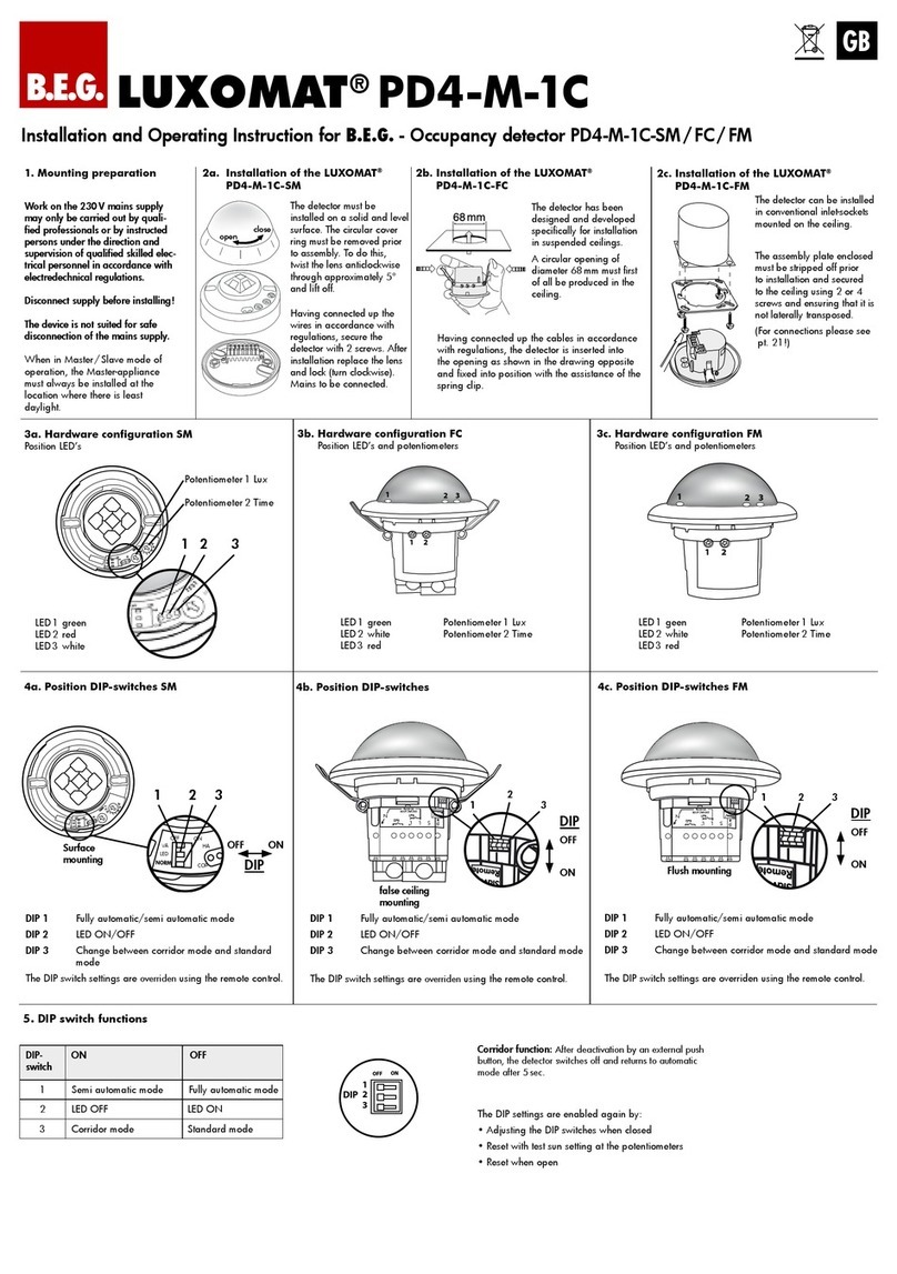
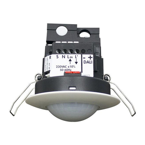
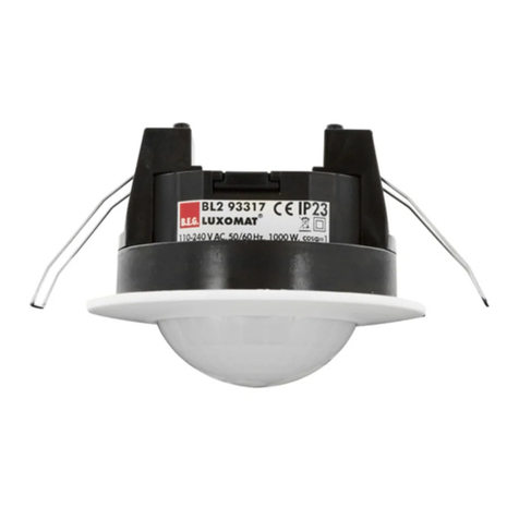
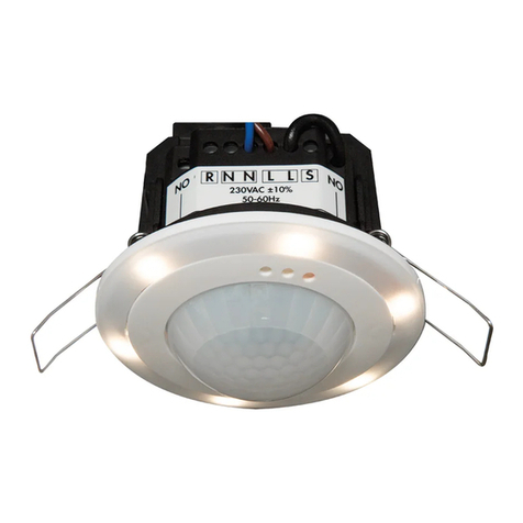
B.E.G. LUXOMAT PD11-BMS-FLAT User manual

DE Montage-Anleitung
Vorbereitung GB Mounting-Instructions
Preparations FR Montage - Instructions
Preparation du montage
RU Инструкция к монтажу
!
Arbeiten an elektrischen Anlagen
dürfen nur von Elektrofachkräf-
ten oder von unterwiesenen
Personen unter Leitung und
Aufsicht einer Elektrofachkraft
entsprechend den elektrotechni-
schen Regeln vorgenommen
werden.
!
Vor Montage Leitung spannungs-
frei schalten!
!
Dieses Gerät ist nicht zum
Freischalten geeignet.
!
DALI ist nicht SELV – Es gelten die
Installationsvorschriften für
Niederspannung.
!
Die DALI-Schraubklemmen dür-
fen nicht mit der Versorgungs-
spannung verbunden werden.
!
Work on the mains supply may
only be carried out by qualified
professionals or by instructed
persons under the direction and
supervision of qualified skilled
electrical personnel in accord-
ance with electrotechnical
regulations.
!
Disconnect supply before
installing!
!
This device is not to be used to
isolate other equipment from the
mains supply.
!
DALI is not SELV –
the installation
instructions for low voltage apply
!
The DALI screw clamps must not
be connected to the supply
voltage
!
Travailler sur le réseau électrique
ne s’improvise pas
, seul un
electricien qualifié et habilité
doit effectuer ce raccordement.
!
Avant de commencer
l’installation, assurez-vous que
l’alimentation est coupée.
!
Pour des questions de sécurité,
nous vous rappelons que ce produit
n’est pas destiné à être branché ou
débranché sous tension.
!
DALI est différent de SELV – Les
prescriptions d‘installation pour
basse tension doivent être
respectées.
!
Les bornes DALI ne doivent pas
être raccordées à 230 VCA!
!
!
!
!
!
Работы с сетью могут выполняться
только квалифицированными
специалистами или обученными
лицами под руководством и
контролем квалифицированного
электротехнического персонала в
соответствии с электро-
техническими правилами.
Отключите питание перед
установкой!
Данное устройство не подходит для
безопасного отключения
электросети
DALI не является SELV -
используйте инструкции по работе
с низким напряжением
Не подключайте зажимы DALI к
источнику напряжения
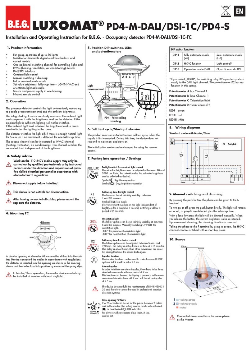
Funktionsweise Operation Fonctionnement Эсплуатация
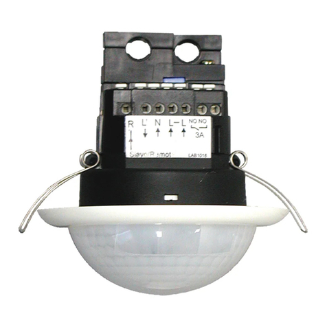
Besonders flacher, adressierbarer
DALI-Multisensor mit nur 0,85 mm
sichtbarer Aufbauhöhe.
Particularly flat, addressable DALI
multisensor with a visible height of
only 0.85 mm.
Multicapteur DALI particulièrement
plat et adressable avec une hauteur
visible de seulement 0,85 mm.
Ультратонкий мультисенсор
DALI с видимой частью
всего 0,85мм
Stromversorgung über DALI-Bus.
Addressier- und nutzbar gemäß IEC
62386 Teil 103 (Steuergerät). Instanz 0
stellt Informationen bezüglich Raum-
belegung und Bewegungserkennung
gemäß IEC 62386 Teil 303 am DALI-
Bus bereit. Instanz 1 stellt LUX Werte
gemäß IEC 62386 Teil 304 am DALI-Bus
bereit. Parametrierung ist über einen
erforderlichen Multimaster-Applika-
tions-Controller eines Drittherstellers
möglich. Dieser Controller muss IEC
62386 Teil 101/103/303/304 unter-
stützen.
Powered via DALI bus. Addressable
according to IEC 62386 Part 103
(control device). Instance 0 provides
information regarding occupancy
and movement for the DALI-Bus
according to IEC 62386 part 303.
Instance 1 provides LUX values for the
DALI-Bus according to IEC 62386 part
304. Parameterization is possible via
mandatory 3rd party Multimaster-Ap-
plication-Controller. This controller
must support IEC 62386 parts
101/103/303/304.
Alimentation par bus DALI. Adressable
et utilisable selon CEI 62386 Partie
103 (unité de commande). La section
0 fournit des informations sur l´attri-
bution des locaux et la détection de
mouvement sur le bus DALI selon IEC
62386 partie 303. La section 1 fournit
les valeurs LUX sur le bus DALI selon
CEI 62386 partie 304. Le paramétrage
est possible par l´intermédiaire d´un
contrôleur d´application multi-maîtres
provenant d´un fabricant tiers. Ce
contrôleur doit être compatible avec la
norme CEI 62386 partie 103/303/304.
Питание по шине DALI
технология DALI мультимастер в
соответствии с IEC 62386 часть 103
Статус 0 передает в шину DALI
информацию о присутствии и движении
в соответствии с IEC 62386 часть 303
Статус 1 передает в шину DALI значение
освещенности в соответствии со
спецификацией IEC 62386 часть 304
Параметризация возможна только через
сторонние контроллеры DALI. Эти
контроллеры должны поддерживать
спецификацию IEC 62386 части
101/103/303/304.
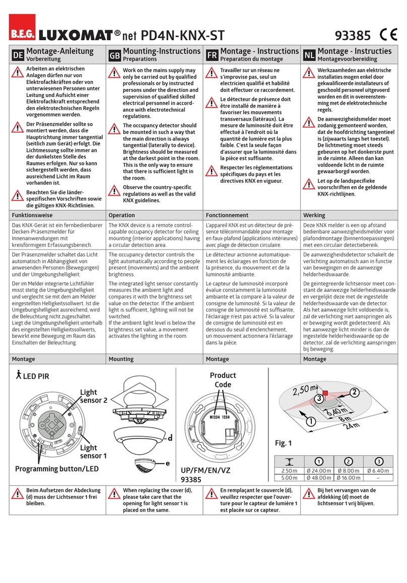
Montage Mounting Montage Монтаж
Fig. 1 Fig. 2 Fig. 3
44 mm
Fig. 1: DALI-Drähte werden mit kleinem
Schlitzschraubendreher ange-
schlossen.
Fig. 1: DALI wires are connected with a
small slotted screwdriver.
Fig. 1: Les cables DALI sont a raccorder
à l‘aide d‘un petit tournevis plat. Fig. 1: Проводка DALI подключается с
помощью отвертки
Fig. 2: Gerät wird in Zwischendecke
eingeführt.
Fig. 2: Device is inserted into false
ceiling.
Fig. 2: Insertion dans un faux plafond Fig. 2: Для скрытого монтажа
Fig. 3:
Falls der Erfassungsbereich des
Melders zu groß ist oder Bereiche
abdeckt, welche nicht überwacht
werden sollen, kann mit den
beiliegenden Abdecklamellen der
Bereich nach Bedarf reduziert bzw.
eingeschränkt werden
.
Fig. 3: In case the detection area of the
detector is too large or areas are
being covered that should not
be monitored, the range can be
reduced or limited by using the
enclosed blinds.
Fig. 3: Si la portée de détection est
trop grande ou couvre des
zones qui ne doivent pas être
détectées, utiliser les obtura-
teurs fournis pour délimiter la
zone de détection souhaitée.
Fig. 3: В случае если зона обнаружения
датчика слишком большая или
покрывает те зоны, в наблюдении за
которыми нет необходимости, то зону
можно ограничить используя линз-
маски
Selbstprüfzyklus Self-test cycle Cycle d‘autocontrôle Самотестирование
In den ersten 20 s nach Zuführung
der DALI-Bus-Spannung durchläuft
der Melder einen Selbstprüfzyklus. In
dieser Zeit reagiert das Gerät nicht auf
Bewegung.
During the first 20 sec after connec-
ting to the DALI bus power, the
product will enter a self-test cycle.
During this time the device does not
respond to movement.
Au cours des premières 20 s après
la remise sous tension, le détecteur
procède à un cycle d‘autocontrôle.
Durant cette période, l‘appareil ne
réagit pas aux mouvements.
При первом подключении(в
течение 20сек) к шине DALI
устройство входит в режим
самотестирования. В это датчик не
реагирует на движения.
LUXOMAT®
net PD11-BMS-FLAT 93330
DE Inbetriebnahme EN Initial operation FR Opération initiale RU Ввод в эксплуатацию
Allgemein: Das Gerät kann nach
der Montage direkt und gemäß
der Anleitung der zur Verfügung
gestellten Software des jewei-
ligen Controller-Herstellers in
Betrieb genommen werden.
General: The device can be
put into service directly after
mounting, following the software
instructions from the relevant
controller manufacturer.
Général : L‘appareil peut être mis
en service directement après le
montage et conformément à la
notice du logiciel du fabricant de
contrôleur mise à disposition.
Устройство может быть введено в
сервисный режим после
установки. Следуйте инструкции
от производителя
A
B
C
LED-Funktionsanzeigen LED function indicators Indicateurs de
fonctionnement à LEDs
Функции LED индикатора
• Kurz an:
AGrün Bewegung
BRot –
CWeiß –
•Blinkt:
AGrün Lokalisierung
BRot Initalisierung
CWeiß Lokalisierung
•Shortly on:
AGreen Movement
BRed –
CWhite –
•Flashing:
AGreen Localization
BRed Initialization
CWeiß Localization
•Allumées (courtes):
AVerte Mouvements
BRouge –
CBlanche –
•Clignotement:
AVerte Localisation
BRouge Initialisation
CBlanche Localisation
•Мигание:
AЗеленый Движение
BКрасный –
CБелый –
•Вспышка:
AЗеленый Обнаружение
BКрасный Инициализация
CБелый Обнаружение
EU-Konformitätserklärung
EU Declaration of conformity Déclaration de conformité UE EU-сертификат соответствия
Das Produkt erfüllt die Richtlinien
über
1. die elektromagnetische
Verträglichkeit (2014/30/EU)
2.
die Niederspannung (2014/35/EU)
3.
die Beschränkung der
Verwendung bestimmter
gefährlicher Stoffe in Elektro- und
Elektronikgeräten (2011/65/EU)
This product respects the direc-
tives concerning
1. electromagnetic compatibility
(2014/30/EU)
2. low voltage (2014/35/EU)
3. restriction of the use of certain
hazardous substances in elec-
trical and electronic equipment
(2011/65/EU)
Ce produit répond aux directives sur
1.
la compatibilité électromagnétique
(2014/30/UE)
2. la basse tension (2014/35/UE)
3. la restriction de l’utilisation
de certaines substances
dangereuses dans les appareils
électriques et électroniques
(2011/65/UE)
Устройство сертифицировано
по следующим параметрам
1.
Электромагнетическая
совместимость(2014/30/EU)
2.
Низковольтное
оборудование(2014/35/EU)
3.
Ограничение использования
опасных и вредных веществ в
электрооборудовании и электронном
оборудовании (2011/65/EU)
Zubehör Accessory
A
cc
essoires Аксессуары
92692 Abdeckring PD11 Ø 100 mm, weiß Cover ring PD11 Ø 100 mm, white Collerette PD11 Ø 100 mm, blanc
Защитное кольцо pd11Ø 100мм,Белый
92537 Abdeckring PD11 Ø 52 mm, weiß Cover ring PD11 Ø 52 mm, white Collerette PD11 Ø 52 mm, blanc
Защитное кольцо pd11 Ø 52мм, Белый
92832 UP-Adapter Set 1 / PD11, weiß
In-wall mounting set 1 / PD11, white
Adaptateur EN Kit 1 / PD11, blanc
Набор для установки в стену 1/PD11, Белый
92833 UP-Adapter Set 2 / PD11, weiß
In-wall mounting set 2 / PD11, white
Adaptateur EN Kit 2 / PD11, blanc
Набор для установки в стену 2/PD11, Белый
92994 Clip-Designrahmen eckig PD11-
DE, weiß matt, ähnlich RAL 9010
Square design frame PD11-FC,
white matt, similar to RAL 9010
Cadre à clipser design carré PD11-
FP, blanc mat, similaire RAL 9010
Квадратная рамка PD11-IB, белая
матовая, схожая с RAL 9010
Reichweite / Produkt Code Range of coverage / Product
Code
Portée / Code produit
Зона покрытия / Код
продукции
N9251 5407
Код продукции
12 3
2.50m Ø 9.00m Ø 6.00 m Ø 3.00m
3m
6m
9m
2
1
3
PD11-BMS
-FLAT
Technische Daten Technical data C
aractéristiques techniques
Технические характеристики
Typ. 16 VDC
(DALI)
Spannung Voltage Tension nominale Сетевое напряжение
2 mA Stromaufnahme Typ. power input Absorption de courant Энергопотребление
0.5 – 2.5 мм2Anschlussklemmen:
für eindrähtige Leiter
Terminal clamps:
for solid one-wire conductors
Bornes de raccordement:
conducteurs à l rigide
Клеммные зажимы для
одножильных проводов
II / IP20
Schutzklasse / Schutzart Class / Degree of protection Classe / Type de Protection Класс / Степень защиты
52 x 48 мм
Abmessungen Ø x H [mm] Dimensions Ø x H [mm] Dimensions Ø x H [mm] Размеры Ø x В[мм]
Fig. 1
1= Ø 9m
2= Ø 6m
3= Ø 3m
Reichweite bei Montagehöhe 2,5m
und Umgebungstemperatur
-25°C - +50°C
1 quer
2 frontal
3 sitzende Tätigkeiten
Range of coverage at mounting
height 2.5 m and ambient tempe-
rature -25°C - +50°C
1 accross
2 towards
3 seated activities
Portée pour une hauteur de
montage de 2,5 m et température
ambiente -25°C - +50°C
1 transversale
2 frontale
3 activité assise
Зона обнаружения при
монтаже на высоте 2,5 метров и
температуре от -25 до 50С
1 перпендекулярно
2 фронтально
3 зона присутствия
64 м2
Überwachte Fläche bei tangen-
tialer Bewegung bezogen auf
2,5 m Montagehöhe
Monitored surface, when the detec-
tor is mounted at 2.5m mounting
height and for tangential approach
Surface contrôlée, lorsque le détec-
teur est monté à la hauteur 2,5m
et pour une approche tangentielle
Зона покрытия при установке на
рекомендуемой высоте и
перпендикулярном движении
2.4 м/ 2.6 м/
2.5 м
Montagehöhe Min./
Max./Empfohlen:
Mounting height min./max./
recommended
Hauteur de montage min./max./
recommandé
Высота монтажа мин./
макс./ рекомендованная
Поликарбонат Gehäuse Housing Boîtier Корпус
10 - 2500 Люкс Helligkeitssollwert Brightness set value Valeur de consigne de luminosité Уровень освещенности
Fig. 4
DE Schaltbild EN Wiring diagram FR
Schéma de câblage
RU Схема подключения
Schematisches Schaltbild – Bitte
beachten Sie beim Anschließen die
Beschriftung der Klemmen am Gerät!
Schematic diagram - when connecting
the detector, please respect the
labelling of the terminal connections
at the device!
Schéma de raccordement de base–
veuillez respecter le marquage des bornes
sur l‘appareil !
При подключении датчика,
соблюдайте маркировку клеммных
соединений на датчике
L
NСторонний контроллер
(со встроенным источником
питания DALI
L
N
DA
DA
DADA
EVG/EB/BE/EVSA
L
N
DA
DA
USB
PD11-DALI-2
-BMS-FLAT
Fehlersuche Trouble shooting Dépannages Проблемы
1. Zu hoher Stromverbrauch an
DALI-Linie
Berücksichtigen Sie bitte bei Ihrem
System die Gesamtstromaufnahme
aller DALI-Einheiten.
1. Power consumption on DALI line
too high
Please be aware of the total power
comsumption of all the DALI units in
your system.
1. Surconsommation sur la ligne DALI
Vérier la consommation totale de
l’ensemble de vos produits DALI.
1. Слишком высокое
энергопотребление на линии DALI
Учтите общее потребление тока
всех устройств DALI в системе
2. Wärmequellen in der näheren
Umgebung
Bendet sich der Melder zum Beis-
piel in unmittelbarer Nähe von Lüf-
tungsschlitzen oder einem Projektor,
können die daraus entstehenden
warmen Luftströmungen eine Bewe-
gungsdetektion auslösen. Platzieren
Sie den Melder in ausreichend
großer Entfernung zu potentiellen
Störquellen wie Lüftungsschlitzen,
Projektoren, Beamern, Kopierern,
Druckern, etc.
2. Heat sources in the vicinity
If, for example, the detector is
located in the immediate vicinity
of ventilation slits or a projector,
the warm air currents can trigger
motion detection. Place the detector
at a sufcient distance from
potential sources of interference
such as ventilation slits, projectors,
beamers, copiers, printers, etc.
2. Sources de chaleur â proximité
Si, par exemple, le détecteur est
proche d’une source de perturbation
(ventilation, luminaire...) , l’air
chaud peut provoquer une
détection de mouvement. Veuillez
placer le détecteur dans une
distance sufsante des sources
d’interférences comme ventilation,
projecteurs, vidéo-projecteurs,
photocopieuses, imprimantes etc.
2. Рядом находится источник тепла
Датчик может регистрировать
ложное движение тепла при
установке рядом с вентиляционной
системой, обогревателем или
другими источниками тепла.
Расположите датчик подальше от
потенциально возможных
источников тепла.
Erweiterte Funktionen Additional functions Fonctions supplémentaires Дополнительные функции
Die Erläuterungen aller Funktionen n-
den Sie in der Funktionsbeschreibung:
www.beg-luxomat.com/de
For a description of all functions
please consult the operation manual:
www.beg-luxomat.com/en
Des informations détaillées sont dispo-
nibles en scandant le QR-Code ci dessous :
www.beg-luxomat.com/fr
Больше информации вы можете
найти на сайте по ссылке:
www.beg-russia.ru
MAN 50303 –V1_010618
B.E.G.
Brück Electronic GmbH
г. Москва, ул. Малая Ордынка, д.
39, стр. 1
Телефон: 8 (499) 236 10 67
E-Mail: info@beg-russia.ru
Internet: www.beg-russia.ru

This manual suits for next models

1

Other B.E.G. Security Sensor manuals

B.E.G. LUXOMAT PD1-M-DIM User guide

B.E.G.

B.E.G. LUXOMAT PD1-M-DIM User guide

B.E.G. LUXOMAT net PD4N-LTMS-RR User guide

B.E.G.

B.E.G. LUXOMAT net PD4N-LTMS-RR User guide

B.E.G. LUXOMAT PD9-S User manual

B.E.G.

B.E.G. LUXOMAT PD9-S User manual

B.E.G. LUXOMAT PD4-M-DALI/DSI-C User guide

B.E.G.

B.E.G. LUXOMAT PD4-M-DALI/DSI-C User guide

B.E.G. LUXOMAT PD4-M-DAA4G User guide

B.E.G.

B.E.G. LUXOMAT PD4-M-DAA4G User guide

B.E.G. LUXOMAT PD4-M-2C-DUO User manual

B.E.G.

B.E.G. LUXOMAT PD4-M-2C-DUO User manual

B.E.G. LUXOMAT PD3-1C User guide

B.E.G.

B.E.G. LUXOMAT PD3-1C User guide

B.E.G. LUXOMAT net PD4-M-DAA4G User guide

B.E.G.

B.E.G. LUXOMAT net PD4-M-DAA4G User guide

B.E.G. LUXOMAT PD4-S-DAA4G User guide

B.E.G.

B.E.G. LUXOMAT PD4-S-DAA4G User guide

B.E.G. LUXOMAT PD4-BMS User manual

B.E.G.

B.E.G. LUXOMAT PD4-BMS User manual

B.E.G. RC-plus next 130 Service manual

B.E.G.

B.E.G. RC-plus next 130 Service manual

B.E.G. LUXOMAT PD4N-KNX-K-DX How to use

B.E.G.

B.E.G. LUXOMAT PD4N-KNX-K-DX How to use

B.E.G. LUXOMAT PD2N-KNX-ST-UP User manual

B.E.G.

B.E.G. LUXOMAT PD2N-KNX-ST-UP User manual

B.E.G. 93386 User manual

B.E.G.

B.E.G. 93386 User manual

B.E.G. LUXOMAT PD4-DIM User guide

B.E.G.

B.E.G. LUXOMAT PD4-DIM User guide

B.E.G. LUXOMAT PD4-S Series User manual

B.E.G.

B.E.G. LUXOMAT PD4-S Series User manual

B.E.G. LUXOMAT PD4-S-GH User guide

B.E.G.

B.E.G. LUXOMAT PD4-S-GH User guide

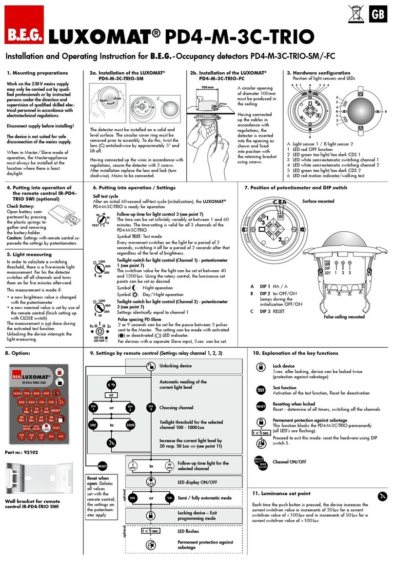
B.E.G. LUXOMAT PD4-M-3C-TRIO Series User guide

B.E.G.

B.E.G. LUXOMAT PD4-M-3C-TRIO Series User guide

B.E.G. LUXOMAT PD2-M-1C User guide

B.E.G.

B.E.G. LUXOMAT PD2-M-1C User guide

B.E.G. LUXOMAT PD4-M-DIM-Corridor Series User guide

B.E.G.

B.E.G. LUXOMAT PD4-M-DIM-Corridor Series User guide

B.E.G. LUXOMAT ALC-K-360 User guide

B.E.G.

B.E.G. LUXOMAT ALC-K-360 User guide

B.E.G. 93385 User manual

B.E.G.

B.E.G. 93385 User manual

B.E.G. LUXOMAT PD2-M-DALI/DSI User guide

B.E.G.

B.E.G. LUXOMAT PD2-M-DALI/DSI User guide

B.E.G. LUXOMAT PD2-M-2C-24V User guide

B.E.G.

B.E.G. LUXOMAT PD2-M-2C-24V User guide

Popular Security Sensor manuals by other brands

Fenwal FenwalNET 2000 Installation, operation and maintenance manual

Fenwal

Fenwal FenwalNET 2000 Installation, operation and maintenance manual

Teknetics Turbo Operation manual

Teknetics

Teknetics Turbo Operation manual

Velleman Whadda WPM407 user manual

Velleman

Velleman Whadda WPM407 user manual

Vimar BY-ALARM PLUS 03835 quick start guide

Vimar

Vimar BY-ALARM PLUS 03835 quick start guide

Maxell MSS-FS1 user manual

Maxell

Maxell MSS-FS1 user manual

Texecom Impaq SC-W installation manual

Texecom

Texecom Impaq SC-W installation manual

SEW-Eurodrive MOVIPRO SDC manual

SEW-Eurodrive

SEW-Eurodrive MOVIPRO SDC manual

Kilsen SK08A Installation sheet

Kilsen

Kilsen SK08A Installation sheet

Bircher Reglomat EsGate 2 Original operating instructions

Bircher Reglomat

Bircher Reglomat EsGate 2 Original operating instructions

Apogee SF-110 owner's manual

Apogee

Apogee SF-110 owner's manual

jablotron JA-158P quick start guide

jablotron

jablotron JA-158P quick start guide

Velleman PIR300 manual

Velleman

Velleman PIR300 manual

GJD D-TECT Pet Immune GJD370 manual

GJD

GJD D-TECT Pet Immune GJD370 manual

LEGRAND Triscan 488TRI3W instruction manual

LEGRAND

LEGRAND Triscan 488TRI3W instruction manual

Aparton SPT-3B user manual

Aparton

Aparton SPT-3B user manual

Ludlum Measurements 42-31H manual

Ludlum Measurements

Ludlum Measurements 42-31H manual

merten ARGUS 360 manual

merten

merten ARGUS 360 manual

PCB Piezotronics ICP W105C02/038AG020AC Installation and operating manual

PCB Piezotronics

PCB Piezotronics ICP W105C02/038AG020AC Installation and operating manual

manuals.online logo
manuals.online logoBrands
  • About & Mission
  • Contact us
  • Privacy Policy
  • Terms and Conditions

Copyright 2025 Manuals.Online. All Rights Reserved.