Büttner Elektronik E-Bike Charger User manual

Introduction
Dear Customer,
with the purchase of the E-Bike charging
system you have chosen a quality product
from HYMER in cooperation with BÜTTNER
ELEKTRONIK.
This E-Bike charging system meets the
highest standards of quality and functio-
nality for a simultaneous charging option
of up to 2 bike batteries, even without
an
external mains connection, in fully
automatic charging mode via alternator
while driving or in manual charging mode,
but also as usual with 230 V mains supply
with always optimal monitoring of your
leisure- / bord battery.
Before the first start-up, the E-bike Charger
control must be set-up. Please read about
this section “Basic Settings” on page 31.
We hope you enjoy your new E-bike
charger charging system.
EN
Your HYMER / BÜTTNER ELEKTRONIK Team
Note
i
Tips and tricks
This icon is used to designate tips, which
help you to utilize your equipment even
easier and more efficient.
BÜTTNER ELEKTRONIK –HYMER E-Bike Charger
24
Warning!
Danger!
!
!
Warns of dangers to persons, damage to
the device or other objects. Injuries or
damage may result from improper hand-
ling. Failure to do so can lead to serious
damage, fire and personal injury!

Table of contents
Introduction............................................................................................................. 24
Table of contents..............................................................................................25
Scope of delivery .............................................................................................25
1General informations and safety instructions....................................................... 26
2Functional description E-Bike Charger control...................................................... 27
Overall diagram..................................................................................................... 28
3Commissioning.............................................................................................30
3.1. Quick overview –E-Bike Charger control........................................................ 30
3.2. Basic settings.................................................................................................. 31
4Operating the E-Bike Charger ............................................................................... 33
4.1. Automated charging while driving.................................................................. 33
4.2. Manual charging mode................................................................................... 34
5General operation ................................................................................................ 35
6Expert set-up E-Bike charge control...................................................................... 36
7Troubleshooting................................................................................................... 38
8Technical Data....................................................................................................... 41
9Warranty .....................................................................................................44
EN
Scope of delivery
BÜTTNER ELEKTRONIK –HYMER E-Bike Charger
25
Quantity
Description
1
E-Bike Charger Control (MT 5005iQ) with display, 200 A shunt with minus cable
adaptor and wiring cable set (10 m control cable, main minus-cable, power supply
cable with fuse and D+ control cable
1
PowerLine Sinus inverter 600 W (MT PL 601) with battery cabling (supply and
fusing, remote control and grounding) and 230 V output with Wago Winsta
coupling system
1
Mains supply tranfer switch unit (MT NU 2301) with mains- and inverter input
and 230 V output with Wago Winsta coupling system
1
RCDI device 10 A –AC fusing with Wago Winsta coupling system
1
Operation manual

1 General Information
Please read all the following instructions
carefully before starting commissioning
your new device.
Safety instructions
The manufacturer does not accept any
liability for damages caused by im-proper
handling and non-compliance with safety
precautions or improper installation.
Changes to the device may result in a loss
of operating license or violation of other
legal requirements (e.g. Equipment and
Product Safety Law, Electronic Compatibi-
lity Law). Upon resale of the conversion,
the per- son responsible for the conversion
becomes the manufacturer and is liable
accordingly. Furthermore, the manufactu-
rer’s warranty is no longer applicable and
a loss of warranty rights may result.
The E-Bike Charger system is suitable for
stationary and for mobile use. The devices
as well as the individual components are
to be protected from moisture and
generally not suitable for outdoor use.
EN
i
For an efficient function of this automated
charging system for e-bike batteries we
recommend,
→
urgently the review of the existing
board battery capacity, as well
the installation of a charging booster
with appropriate cable cross-sections
for efficient charging option while
driving, as well
retrofitting a solar system for charging
when stationary
→
→
BÜTTNER ELEKTRONIK –HYMER E-Bike Charger
26

2 Function description of the E-Bike Charger Control
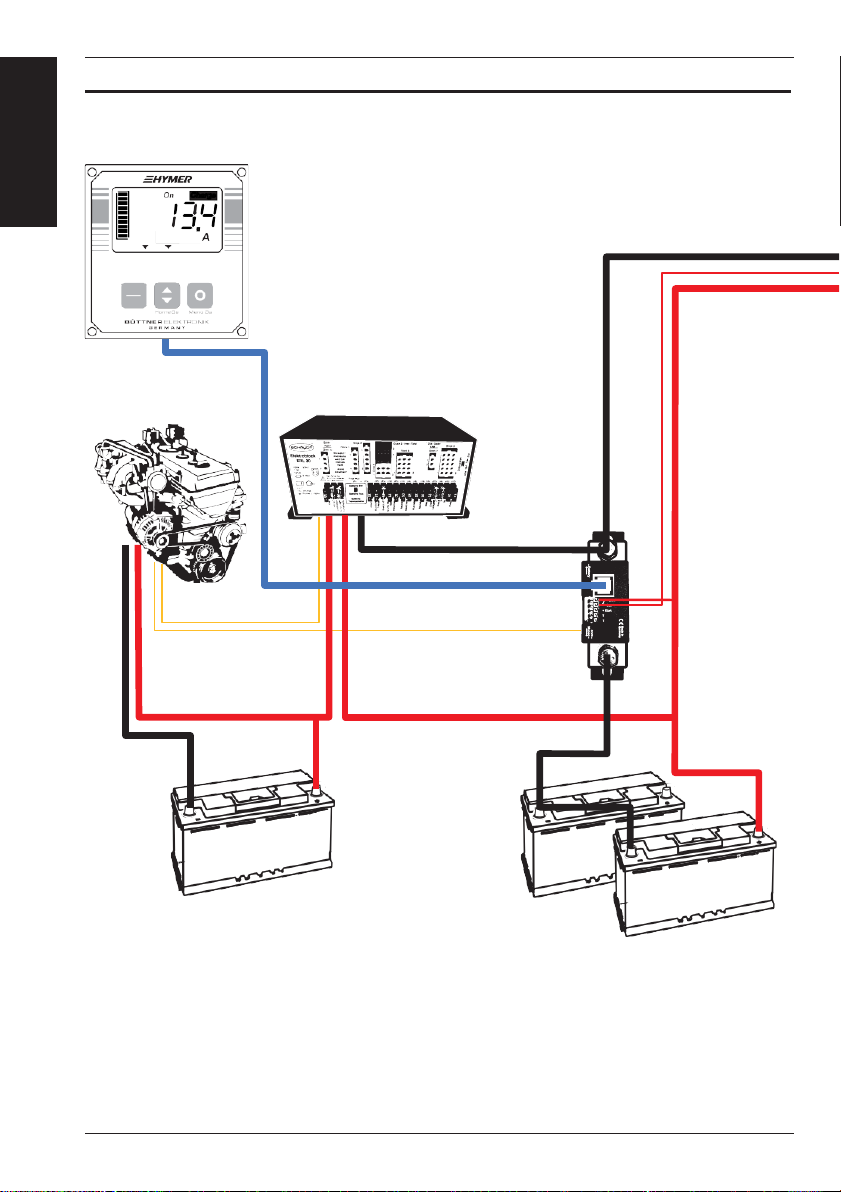
With the help of the measuring shunt in
the main minus cable on the board battery
system, the control system constantly de-
tects whether the board battery is being
charged or discharged and uses this to de-
termine the remaining capacity which is
actually available. This is the basic require-
ment for automated charging of the E-bike
batteries, which is only possible in defined
capacity ranges of the board batter, both
in driving and stationary mode.
When driving, in addition to checking the
capacity range of the board battery, the
inverter is only switched on after the dy-
namo + signal of the alternator has been
detected, so that the connected chargers
can charge the E-bike batteries.
EN
A charging booster is required for efficient
charging, especially for E6 vehicles!
For a E-Bike charger with 180 W power
consumption, the inverter consumes about
18 A DC current. With a 30 A charging
booster, the bike battery and the board
battery can be charged at the same time.
A charging booster with at least 50 A should
be available for 2 connected E-bike batteries.
i
At the camp site with a power connection,
the mains transfer switch unit ensures that
the sockets for the e-bike power packs are
also automatically supplied.
Without mains supply, recharging can also
be started manually, as long as there is
sufficient board-battery capacity available
until the system switches off automatically.
For efficient charging while stationary, the
board-battery capacity must be available
and a solar system is recommended!
Up to 500 Wh from the board battery
system can be required to recharge just
one e-bike battery. This already corres-
ponds to the maximum amount of energy
that can be drawn from a 100 Ah lead type
battery! This means that the board battery
system should have at least twice the capa-
city, and it should be possible to compen-
sate the consumption for charging with a
solar system.
With a 125 Wp module, 500 Wh can be
harvested on a sunny day.
i
BÜTTNER ELEKTRONIK –HYMER E-Bike Charger
27

2 Function description of the E-Bike Charger Control
Overall diagram
EN
E-Bike Charger
1
control
%D+
E-B IKE CHARGER
ON
OFF
Central electrics
Vehicle engine
and alternator
(EBL)
D+ Signal
E-Bike Charger
Shunt
Starter-battery
Board-battery
BÜTTNER ELEKTRONIK –HYMER E-Bike Charger
28
Remote
Input

2 Function description of the E-Bike Charger Control
EN
Pure sine inverter
PowerLine PL 601
RCD device
Charging sockets
Mains transfer
switch unit
NU 2301
MT NU 2300
Charging sockets
max. 600 W
RCD device
Mains input
Vehicle
Mains input
BÜTTNER ELEKTRONIK –HYMER E-Bike Charger
29

3Commissioning
3.1 Quick overview –E-Bike Charger control:
❶
EN
❶
❶
❶
2
% D+
E-B IKE CHARGER
ON
OFF
❶
❶
❶
Operation mode –selection button
Automated charging while driving:
short push on button →Operation
mode displaying
❶
:
„1“
Manual charging mode: 3 s –push on
button →Operation mode displaying
❶
:
„2“
Displaying operation mode:
1: Automated charging while driving
2: Manual charging mode
Displaying operational readiness %:
An arrow in the display above the %
symbol indicates that the board bat-
tery provides sufficient remaining ca-
pacity for charging the E-bike batteries.
Displaying operational D+:
An arrow in the display above the D+ -
symbol indicates that the charging
current is provided while vehicle engine
is running
❶
❶
Display screen –selection button
For displaying power consumption
(negative sign) or charge in A, available
capacity in Ah and %, remaining time
display in h, as well as voltage display
of the board battery in the main dis-
play
❶
❶
Graphical displaying of available
battery-capacity
Function control „On“ and
will only be displayed when E-Bike bat-
tery chargng takes place and the board
battery provides sufficient capacity
❶
Menu –button
Switching display On/Off: →short push
on button
Set-up: 3 s –long push on button →Set-
❶
❶
up nominal capacity in Ah,
type and display brightness
battery
Main screen
❶
Expert Mode: 10 s –long
push on
button → Set-up of switch-on / switch-
off thresholds in %
(see 6. Expert set-up)
BÜTTNER ELEKTRONIK –HYMER E-Bike Charger
30

3 Commissioning
3.2 Basic settings
Set-up of the E-Bike charger control:
EN
Push Menu-button
for 3s
Set-up the total nominal capacity of the battery-system
(Factory default 100 Ah)
Increase capacity +1
Decrease capacity -1
Set-up battery type acc. table 1
(Factory default 34):
Increase value +1
Decrease value -1
Set-up display brightness
brighter
darker
save set-up
BÜTTNER ELEKTRONIK –HYMER E-Bike Charger
31
Battery type
Battery charging voltage
Set-up value
Blei-Säure/Nass
14.4
24
Gel
14.4
53
AGM 14.4
14.4
34
AGM 14.4–14.8
14.7–14.8
47
LiFePO4 13.9 V
13.9
89
LiFePO4 14.2 V
14.2
82
LiFePO4 14.4 V
14.4
84
LiFePO4 14.6 V
14.6
86
LiFePO4 14.8 V
14.8
88

3 Commissioning
Commissioning pure-sine inverter
EN
3-step switch
Must be in position I
= Remote !
+
–
The PowerLine inverter has an ON / OFF / REMOTE device
switch
❶
.
In this way, the functionality of the inverter can be
determined.
When the switch is in the OFFposition, the inverter is switched off.
In the ON switch position, the inverter is permanently switched
on regardless of the remote control input
REMOTE
OFF
❶
ON
❶
❶
CHECK
POWER
TheswitchpositionREMOTEenablestheinvertertobeoperated
via the remote control input.
The operating status of the inverter is indicated by 2 LEDs on
the front of the device.
The green “POWER”
❶
lights up when the inverter is switched
on and 230 V AC voltage is generated at the output.
The red “CHECK”
❶
indicates when operation is restricted or
has been canceled.
BÜTTNER ELEKTRONIK –HYMER E-Bike Charger
32
Warning!
No intelligent and monitored
!
!
E-bike charging possible!

4Operating the E-Bike Charger
4.1 Automated charging while driving (Operation mode 1)
❶
EN
❶
❶
1
% D+
E-B IKE CHARGER
ON
OFF
To proceed automated charging of the
E-bike batteries the basic settings must be
carried out first!
i
❶
Preparations:
1. Connect the E-Bikebattery to thepower
supply unit
2. Connect the power supply unit or up to
2 units to the referenced E-bike
charging socke(s) up to max. 600 W
(usually in the rear garage)
3.
By briefly pressing the button
❶
the
automated charging mode is activated
while driving –operation mode 1!
For control, the number “1” must be
i
shown in the lower left corner of the dis-
play
❶
!
Start of charging:
When the vehicle engine is started and the
board battery has sufficient capacity, a
small arrow appears in the display
❶
above the % - and D+ symbol.
This activates the switching output of the
measuring shunt and switches the inver-
ter on. As a control, in the display
❶
“On”
If no arrow is displayed above the %
symbol, the board battery will be charged
first while driving until sufficient capacity is
ensured and then recharging of the E-bike
battery starts automatically.
The display
❶
then shows “blinking“ “On”
i
and no
symbol.
This display also applies if the engine has
not yet been started or switched off.
and
will be shown.
Charging progress:
When driving will be interrupted or the
motor is switched off in start / stop mode,
the inverter remains switched –on for a
limited time. Will be within 5min. no en-
gine running (D+ signal) be detected, the
inverter is switched –off, but charging is
automatically resumed within 5 hours if
the engine will be retarted again. The pro-
gram is then terminted and may have to
be restarted again. A short press on the
On / Off button deactivates the active
mode manually at any time.
i
For control, no number will be shown in
the left corner of the display
❶
!
BÜTTNER ELEKTRONIK –HYMER E-Bike Charger
33

4 Operating the E-Bike Charger
4.2 Manual charging mode (Operation mode 2)
❶
EN
❶
2
% D+
E-B IKE CHARGER
ON
OFF
To proceed automated charging of the
E-bike batteries the basic settings must be
carried out first!
i
❶
Preparations:
1. Connect the E-Bike battery to thepower
supply unit.
2. Connect the power supply unit or up
to 2 unis to the referenced E-bike
charging socket(s) up to max. 600 W
(usually in the rear garage).
3.
By pressing the button
❶
for 3 s the
manual charging mode is activated
while driving –operation mode 2.
For control, the number “2” must be
shown in the lower left corner of the dis-
play
❶
!
i
Start of charging:
If the capacity of the board battery is suffi-
cient for operating mode 2, a small arrow
will appear in the display
❶
above the % -
symbol.
This activates the switching output of the
measuring shunt and switches the inver-
ter on. As a control, in the display
❶
“On”
If no arrow is displayed above the % - symbol,
the board battery must be recharged first
until sufficient remaining capacity is ensu-
red again.
The display
❶
then shows the “blinking”
i
“On” and no
symbol.
5 hours after activating operation mode 2,
this charging mode is automatically deacti-
vated.
and
will be shown.
i
For control, no number will be shown in
the left corner of the display
❶
!
BÜTTNER ELEKTRONIK –HYMER E-Bike Charger
34

5 General operation
Switching display On/Off
EN
❶
By a short push on button
❶
display can be switched off and on.
the
❶
2
% D+
E-B IKE CHARGER
The control will not be affected! The display
can be switched off if the controller is not
used for a longer period of time.
i
ON
OFF
❶
❶
Displaying of various board battery-informations
By briefly pressing the button
❶
selected in the main display
❶
.
various board- or leisure battery screens can be
Battery voltage screen in Volt
Current screen in Ampère
Actual measured current value. Positive charging current (unsigned)
that flows into the on-board battery, or consumer current (negative
sign), if e.g. E-bike charging takes place in mode 2.
Capacity screen in Ampère-hours and percentage
The charging and discharging of the battery is recorded and
balanced by a microprocessor. Programmed characteristic cur-
ves and correspondingly set battery types enable an automatic
evaluation of the battery load and calculation of the remaining
charge. Self-discharge of the battery during long idle times is
taken into account, the full charge status is automatically
recognized and corrected if necessary. The graphic display of the
remaining battery capacity
❶
corresponds to the % - screen in
10% steps.
Remaining time in battery in hours
The remaining time is calculated from the remaining capacity (up
to the set switch-off threshold) and the actual current. If there is
no power consumption, no remaining time can be calculated and
the placeholder “ -.- ” is displayed accordingly.
BÜTTNER ELEKTRONIK –HYMER E-Bike Charger
35

6 Expert set-up E-Bike charge control
The switch-on thresholds for the start of
charging and the switch-off threshold for
aborting the E-bike battery charge depend
on the respective operating mode, auto-
mated charging while driving (mode 1)
or manual charging (mode 2), the battery
type (LiFePO4 or Pb types) and the battery
capacity of the board battery and are pre-
set but can be changed if necessary.
EN
Switch-on/ switch-off threshold values for charging operation mode 1 (driving mode):
Switch-on threshold = 95% - LiFePO4 & all Pb types
Switch-off threshold = 90% - LiFePO4 & all Pb types
Switch-on/switch-off threshold values for charging operation mode 2 (manual operation):
Switch-on threshold = 70% - LiFePO4
Switch-off threshold = 50% - LiFePO4
Switch-on threshold = 95% - all Pb types
Switch-off threshold = 75% - all Pb types
BÜTTNER ELEKTRONIK –HYMER E-Bike Charger
36
Warning!
These Switch-on/ switch-off threshold values are preset to maintain the
!
!
greatest possible autonomy while at the same time ensuring the longest
service life of your board battery and should only be changed by qualified
personnel.

6 Expert set-up E-Bike charge control
To change these on / off threshold values, press the menu key
for 10 seconds.
EN
Mode 1
Automated charging
while driving
Switched output ON - switching
threshold capacity
Increase capacity +1
1
Decrease capacity -1
Switched output OFF - switching
threshold capacity
Increase capacity +1
1
Decrease capacity -1
Switched output ON - switching
threshold capacity
Mode 2
Manual charging
operation
Increase capacity +1
2
Decrease capacity -1
Switched output OFF - switching
threshold capacity
Increase capacity +1
2
Decrease capacity -1
BÜTTNER ELEKTRONIK –HYMER E-Bike Charger
37

7 Troubleshooting
Please note the table below for initial remedial measures
in the event of charging problems with your E-bike batteries.
EN
BÜTTNER ELEKTRONIK –HYMER E-Bike Charger
38
Fault
Cause
Solution
Display of E-Bike
Charger control
without screen
Switch-on display by short
push on the right button
No charging of the
E-bike batteries on
mains supply at the
camp site
Check mains input
RCD device
The switch position must be at the top.
If this device can no longer be switched on/releases
again, switch off / unplug all 230 V consumers or
contact an electrician!
Check RCD device
for charging
sockets
If this device can no longer be switched on, the
plugged in E-Bike power supply unit possibly is
defective ! Unplug and switch-on the RCD again,
respectively contact an electrician!
No charging of the
E-bike batteries
while driving /
running engine
Charging operation
mode 1 must be
activated
Verification
according to 4.1
Check whether the
display shows “On”
and !
If “On” only flashes and there are no arrows in
the display above the % - and D+ sign, the board
battery is below the switch-on threshold, see 6.
Expert set-up and needs to be charged first.
Check inverter
1. 3-step switch must be in position “Remote”, see 2.
2. Check inverter indicators and
acoustic signals, see 7.1.
Check RCD
device for
charging sockets
If this device can no longer be switched on, the
plugged in E-Bike power supply unit possibly is
defective! Unplug and switch-on the RCD again,
respectively contact an electrician!
No charging of the
E-bike batteries in
manual charging
operation
Charging operation
mode 2 must be
activated
Verification according to 4.2.
Check whether
the display “On”
and
If “On” only flashes and there are no arrows in
the display above the % - and D+ sign, the board
battery is below the switch-on threshold, see
6. Expert set-up and needs to be charged first.
Check inverter
1. 3-step switch must be in position “Remote”, see 2.
2. Check inverter indicators and
acoustic signals, see 7.1.
Check RCD
device for
charging sockets
If this device can no longer be switched on, the
plugged in E-Bike power supply unit possibly is
defective! Unplug and switch-on the RCD again,
respectively contact an electrician!

7Troubleshooting
7.1 Inverter indicators and acoustic signals
EN
BÜTTNER ELEKTRONIK –HYMER E-Bike Charger
39
Input parameter
Voltage range
Description
Normal operation
11.5V –14.0V
Optimal operation
13.0V –14.0V
Low-voltage warning
11.2V –10.7V
Acoustic signal 2 x / pause
STOP Low-voltage
< 10.7V +/-0.2V
Inverter OFF, Acoustic signal 3 x /pause
RESTART Low-voltage
> 12.0V +/-0.2V
Inverter ON
STOP High-voltage
> 15,0 V
Inverter OFF, Acoustic signal 5 x/ pause
Voltages >16V may cause damage in the
device even when not in operation!
Status
LED Inverter/
Extern
LED Check
Acoustic
signal
Output
230V
Inverter Start
ON
ON (1sec)
1 x
ON
Normal operation
ON
OFF
OFF
ON
Low-voltage warning
ON
OFF
2 x / pause
ON
Low-voltage
ON
ON
3 x / pause
ON
High-voltage
ON
ON
4 x / pause
ON
Overtemperature
ON
ON
5 x / pause
ON
Overload warning
ON
OFF
1 x short / pause
ON
Overload
OFF
ON
continuous
OFF
Short-circuit
OFF
ON
continuous
OFF

7 Troubleshooting
7.2 Switching back on inverter / Reset CHECK Anzeige
EN
If the inverter has stopped operation
because of one of the previously described
reasons, a manual restart can be done. To
do so the inverter has to be switched OFF
at the device switch until the red LED is
extinguished. After a short waiting time,
the inverter can be restarted.
At the reboot the inverter now checks all
the input parameters, same as each nor-
mal startup. If there is still a parameter
over or below the limit values, the start is
prevented, and the corresponding status
message is shown on LED and acoustic
signal.
In case of overtemperature, wait 5 to 10 mi-
nutes for cooling down the device before
restart. In case of overload, turn off the load
and reduce the connected consumers.
i
7.3 Device protetion
The inverter is internally protected against damage in the following events:
→
→
Low-voltage: The inverter switches off
when the battery voltage drops below
the STOP threshold. And re-starts
again when the voltage is above the
threshold of RESTART.
Overvoltage: The inverter switches
off when the battery voltage is above
the STOP threshold and re-starts
again when the voltage is below the
threshold.
Overtemperature: The inverter switches
off when the internally permissible
maximum temperature is exceeded.
Only after cooling down and reset the
inverter could be restarted.
Overload:Theinverterstopsoperation
and switches off. After short waiting
time the inverter starts up again au-
tomatically.
Output short circuit: The inverter
switches off if the absolute limit values
for output power are exceeded. The
inverter can only be restarted after it
has been manually switched on again
→
→
→
BÜTTNER ELEKTRONIK –HYMER E-Bike Charger
40

8 Technical Data
EN
Declaration of conformity:
According to the provisions of the directives 2006/95 / EC, 2004/108 / EC, 95/54 / EC,
this product complies with the following standards or normative documents:
EN55014; EN55022 B; DIN14685; DIN40839-1; EN61000-4-2; EN61000-4-3; EN
61000-4-4
BÜTTNER ELEKTRONIK –HYMER E-Bike Charger
41
Precision-Smart-Shunt: 200 A
Load capacity Smart-Shunt
Nominal current
200 A
Contin. current (ventilated)
240 A
Max. current 15 min
300A
Max. current 7 min
400 A
Max. peak current
900 A
Dimension Smart-Shunt (mm)
135 x 32 x 44
Weight
240 g
Display unit
Technic
LCD Display with specific segments
Screen dimension
49 x 28 mm
Illumination
white LED
Dimensions (mm)
80 x 85 x 24
Installation dimension
electronics (mm)
ca. 66 x 72
Weight
ca. 55 g
E-Bike Charger control –MT 5005iQ
Nominal voltage
12 V
Operating voltage range
8...32 V
Current consumption
4...60 mA, depending display brightness
Battery types
see tabel “battery type”
Ambient conditions,
humidity
max. 95% RF, not condensing

8 Technical Data
EN
Declaration of conformity:
The product complies with the requirements of the following directives and stan-
dards of the European Union:
Directive 2014/30 / EU standards:DIN EN 61000-6-3, VDE 0839-6-3: 2011/09,
(B1:2012-11); DIN EN 61000-6-4; VDE 0839-6-4:2011-09; DIN EN 55022; VDE 0878-
22:2011-12, B1:2016-08: (CISPR 22:2008 mod.); DIN EN 55011; VDE 0875-11:2011-04,
A1:2015-11; DIN EN 55014-1 VDE 0875-14-1:2012-05, A1:2016-03
DIN EN 61000-6-1 VDE 0839-6-1:2016-05; DIN EN 55014-2 VDE 0875-14-2:2016-01
Low voltage directive 2014/35/EU Standards:
DIN EN 60335-1:2012/A11: 2014; DIN EN 60730-1:2017-05; VDE 0631-1:2017-05
ROHS and REACH compliant:
DIN EN 50581:2013-02; VDE 0042-12:2013-02, VDE 0042-12:2013-02 (EG) Nr.
1907/2006 (REACH)
BÜTTNER ELEKTRONIK –HYMER E-Bike Charger
42
Pure sine inverter –MT PL 601 SI
Nominal voltage
12V DC
Input voltage range
10,5 –15V DC
Output voltage
230V/AC/50Hz/THD <3%
Nominal power
600W
Overload / 1s
1000W
Standby current
0.7A
Nom. power (max.current)
60A
Efficiency
87–94%
Weight approx.
2100g
Dimension L x W x H (mm)
250 x 165 x 85
Battery cabling
1.2m –10mm²
Cable fusing
60A
Ventilation
Depending temperature- and load
Protections
Overlaod, overtemperature, short-circuit on output,
Overvoltage, Undervoltage
Remote Input
12V DC/30mA

8 Technical Data
EN
Declaration of conformity:
The product is in line with the requirements of the following European Union direc-
tives and standards:
Directive 2014/30/EU Standards: DIN EN 61000-6-3, VDE 0839-6-3: 2011/09,
(B1:2012-11); DIN EN 61000-6-4; VDE 0839-6-4: 2011-09; DIN EN 55022; VDE
0878-22:2011-12, B1:2016-08: (CISPR 22:2008 mod.); DIN EN 55011; VDE 0875-11:
2011-04, A1:2015-11; DIN EN 55014-1 VDE 0875-14-1:2012-05, A1:2016-03; DIN
EN 61000-6-1 VDE 0839-6-1:2016-05; DIN EN 55014-2 VDE 0875-14-2:2016-01
Low voltage directive 2014/35/EU standards: DIN EN 60335-1:2012/A11: 2014;
DIN EN 60730-1: 2017-05; VDE 0631-1:2017-05
ROHS und REACH compliant: DIN EN 50581:2013-02; VDE 0042-12:2013-02, VDE
0042-12:2013-02 (EG) Nr. 1907/2006 (REACH)
BÜTTNER ELEKTRONIK –HYMER E-Bike Charger
43
Mains transfer switch unit –MT NU2301
Input voltage
230 V AC, 50 Hz, pure sinewave
Output voltage
230 V AC, 50 Hz
Input current
(max.) 10 A
Output power
(max.) 2300 VA
Switchover time
ca. 0,5 s
Internal fuse
T 10 A / 250 V
Protection class
Overload, Short-circuit, Reverse current
Temperature range
-20° C …. +60° C
Protection class
IP 55
Dimension
113 x 93 x 55 mm
Weight
ca. 195 g
This manual suits for next models
1
Table of contents
Other Büttner Elektronik Batteries Charger manuals
Popular Batteries Charger manuals by other brands

ABB
ABB HT571256 Operation manual

Armytek Optoelectronics
Armytek Optoelectronics Uni C2 user manual

PRACHT
PRACHT NRG1010 manual

Applied Energy Solutions
Applied Energy Solutions Maverick Installation and operating instructions

HYBRESIS
HYBRESIS 199586 Instructions for use

Motorola solutions
Motorola solutions NNTN8038 user guide