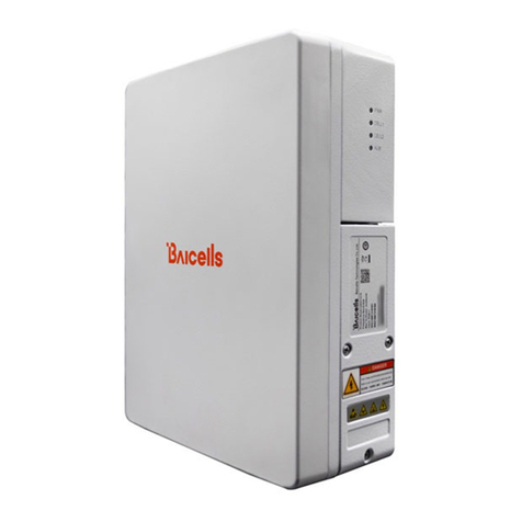
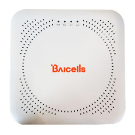
Baicells Atom OD040615 User manual

Atom OD040615 Outdoor
Low-Gain & High-Gain CPE
User Manual
BaiCE_AP_2.4.7_NA
BaiCE_BG_1.6.20
January 2022
Version 1.12

2
About This Document
This document is intended for installers and subscribers setting up and operating the Baicells Atom
OD040615* Outdoor Low-Gain and High-Gain Customer Premise Equipment (CPE), aka User Equipment
(UE). The Atom unit provides a way for users to connect to the Internet through broadband wireless access
to Long-Term Evolution (LTE) backhaul networks. The information covers how to install, configure basic
settings, monitor, and perform basic troubleshooting for the outdoor CPE. If you are using a Baicells indoor
CPE, please refer to the Atom ID0406-6.5 Indoor CPE User Manual.
*NOTE: "OD" stands for outdoor. The "04" designation stands for CAT4, "06" stands for CAT6, and “15” stands
for CAT15. These categories are related to the LTE standards requirements for user equipment. Model
numbers are shown in the product datasheets, which can be found at Baicells.com > Resources > Documents.
This document is applicable to the following Atom Outdoor CPEs:
•Atom OD04L – Outdoor CAT4Low-Gain CPE,model EG7035L
•Atom OD04H – Outdoor CAT4 High-Gain CPE,model EG7035E
•Atom OD06L – Outdoor CAT6/7 Low-Gain CPE, model EG7010C
•Atom OD06H – Outdoor CAT6/7 High-Gain CPE, model EG7010A
•Atom OD06-LX– Outdoor CAT6Low-Gain CPE, model EG8013L
•Atom OD15/OD15 EUD – Outdoor CAT15 High Gain CPE, model EG8015G
Terms used in this document or related to LTE are listed in alphabetical order and described in Acronyms
and Abbreviations, which can be found at Baicells.com > Resources > Documents.
New in This Release
The following updates have been provided in this release:
•Updates reflect changes to new software BG 1.6.20
•Updated to include applicable models
•Updated to include CAT6-LX Outdoor CPE
•Updated to include CAT15 Outdoor High-Gain CPE
•Updated MTU setting in section 7.7.2, step 4
•Updated the Spectrum Access System (SAS) information in section 7.8
Copyright Notice
Baicells Technologies, Inc., copyrights the information in this document. No part of this document may be
reproduced in any form or means without the prior written consent of Baicells Technologies, Inc.
Disclaimer
The information in this document is subject to change at any time without notice. For more information,
please consult with a Baicells technical engineer or the support team. Refer to the “Contact Us” section
below.

3
Revision Record
Date
Version
Description
SMEs/Contributors
Writer/Editor
05-Jan-2022
V1.12
Updated for BaiCE_BG_1.6.20
Seng Tang, Abel Lamas, Anna
Ch
Catherine Philley
18-Dec-2020
V1.11
Updated for BaiCE_AP_2.4.7_NA and
BaiCE_BG_1.6.5.3
Jesse Raasch
Jocelyn Watson
16-Nov-2020
V1.10
Added SAS configuration section
Nitisha Potti, Pengyu Chen
Sharon Redfoot
22-Oct-2020
V1.9
Updated for BaiCE_AP_2.4.5 and
BaiCE_BG_1.6.4
Pengyu Chen, Nitisha Potti
Sharon Redfoot
2-Oct-2020
V1.8
Updated for firmware version
BaiCE_BG_1.5.0, 1.6.1 and
BaiCE_AP_2.4.2_NA, 2.4.4
Nitisha Potti,
TangHoucheng, WangYong
Jocelyn Watson
19-Feb-2020
V1.7
New branding
Chris Culver
Sharon Redfoot
18-Sep-2019
13-Sep-2019
V1.6
V1.5
SME comments
Updated for naming convention
change, BaiCE_AP_2.2.1_NA (CAT4)
and BCE_MD-1.0.1-B036SP28-NA
(CAT6/7/15) and general info; added
more detail for key GUI windows as
well as basic user maintenance and
troubleshooting section
From Configuration &
Network Admin Guide
published Sept 3, 2019;
TangHoucheng, Xuanjianxi,
Nitisha Potti
Sharon Redfoot
Contact Us
Baicells Technologies Co., Ltd.
China
Baicells Technologies North America, Inc.
North America
Address: 3F, Bldg. A, No. 1 Kai Tuo Rd, Haidian
Dist, Beijing, China
Address: 5700 Tennyson Pkwy., #300, Plano, TX
75024, USA
Phone: +86-10-62607100
Phone: +1-888-502-5585
E-mail: contact@Baicells.com Email: sales_na@Baicells.com or
support_na@Baicells.com
Website:
www.Baicells.com
Website:
https://na.Baicells.com

4
Table of Contents
1INTRODUCTION ............................................................................................................................................... 7
2FEATURES......................................................................................................................................................... 7
3PARTS & MATERIALS........................................................................................................................................ 8
4DESCRIPTION ................................................................................................................................................... 9
5PREPARING TO INSTALL ................................................................................................................................. 12
6INSTALLATION................................................................................................................................................ 12
7BASIC CONFIGURATION ................................................................................................................................. 20
7.1 LOG IN ..................................................................................................................................................... 20
7.2 CHECK CURRENT STATU S ICONS ..................................................................................................................... 22
7.3 CONFIGURE WAN SETTINGS ......................................................................................................................... 23
7.3.1 CAT4 .................................................................................................................................................. 23
7.3.2 CAT6/7/15 ......................................................................................................................................... 25
7.4 WIFIDOG.................................................................................................................................................. 29
7.5 CONFIGURE CONNECTION MODE /CONNECTION SETTINGS ................................................................................. 30
7.6 CONFIGURE SCAN MODE /CELL SELECTION...................................................................................................... 31
7.5.1 Overview ........................................................................................................................................... 31
7.5.2 CAT4 .................................................................................................................................................. 32
7.5.3 CAT6/7/15 ......................................................................................................................................... 34
7.7 CONFIGURE APN MANAGEMENT /EDIT APN PROFILE ....................................................................................... 36
7.7.1 Overview ........................................................................................................................................... 36
7.7.2 Configure Local EPC APN ................................................................................................................... 37
7.8 CONFIGURE SAS ........................................................................................................................................ 38
7.9 VERIFY NETWORK CONNECTION..................................................................................................................... 38
8BASIC TROUBLESHOOTING ............................................................................................................................ 39
8.1 DEVICE INFORMATION ................................................................................................................................. 39
8.2 LTE STATUS ............................................................................................................................................... 39
8.3 THROUGHPUT STATISTICS ............................................................................................................................. 40
8.4 APN STATUS /INTERNET STATUS ................................................................................................................... 40
8.5 LAN STATUS ............................................................................................................................................. 41
8.6 DEVICES LIST ............................................................................................................................................. 42
5
List of Figures
Figure 1: LTE Network Architecture............................................................................................................. 7
Figure 2: Dimensions................................................................................................................................... 9
Figure 3: Atom OD0406 Low-Gain LEDs & Interfaces ................................................................................ 10
Figure 4: Atom OD0406 High-Gain LEDs & Interfaces ............................................................................... 10
Figure 5: Atom OD15 High-Gain LEDs & Interfaces ................................................................................... 11
Figure 6: SIM/USIM Card Atom OD0406 ................................................................................................... 13
Figure 7: SIM/USIM Card Atom OD15 ....................................................................................................... 13
Figure 8: PoE Adaptor Atom OD0406........................................................................................................ 14
Figure 9: PoE Adaptor Atom OD15............................................................................................................ 14
Figure 10: Completed Grounding.............................................................................................................. 15
Figure 11: Low-Gain CPE Ground Screw.................................................................................................... 15
Figure 12: High-Gain CPE Ground Screw and Ground Row ....................................................................... 16
Figure 13: Power Adaptor ......................................................................................................................... 16
Figure 14: Rubber Band ............................................................................................................................ 17
Figure 15: Bracket ..................................................................................................................................... 17
Figure 16: Attach CPE ................................................................................................................................ 17
Figure 17: Tighten Screws ......................................................................................................................... 17
Figure 18: Threaded Rod........................................................................................................................... 18
Figure 19: Omega Clamps ......................................................................................................................... 18
Figure 20: Mark Holes for Drilling ............................................................................................................. 18
Figure 21: Fix Bracket to Wall.................................................................................................................... 19
Figure 22: Attach CPE................................................................................................................................ 19
Figure 23: Mark Holes for Drilling ............................................................................................................. 19
Figure 24: Attach CPE................................................................................................................................ 20
Figure 26: First Login................................................................................................................................. 20
Figure 27: Change Password ..................................................................................................................... 21
Figure 28: Login......................................................................................................................................... 22
Figure 29: Status Icons .............................................................................................................................. 22
Figure 30: WAN Settings (CAT4) ................................................................................................................ 24
Figure 31: WAN Settings (CAT6/7/15) (1 of 2) ........................................................................................... 26

6
Figure 32: WAN Settings (CAT6/7/15) (2 of 2) ........................................................................................... 27
Figure 33: Wifidog Settings ....................................................................................................................... 29
Figure 34: Connection Mode..................................................................................................................... 30
Figure 35: Scan Mode/Cell Selection......................................................................................................... 31
Figure 36: Frequency Lock (CAT4) ............................................................................................................. 32
Figure 37: Cell Lock (CAT4) ........................................................................................................................ 33
Figure 38: PCI Lock (CAT4)......................................................................................................................... 34
Figure 39: Dedicated EARFCN (CAT6/7/15) ............................................................................................... 35
Figure 40: PCI Lock (CAT6/7/15)................................................................................................................ 35
Figure 41: PCI-only Lock (CAT6/7/15)........................................................................................................ 36
Figure 42: APN Management / Edit APN Profile........................................................................................ 37
Figure 43: Device Info ............................................................................................................................... 39
Figure 44: LTE Status ................................................................................................................................. 40
Figure 45: Throughput Statistics ............................................................................................................... 40
Figure 46: APN Status................................................................................................................................ 41
Figure 47: LAN Status ................................................................................................................................ 41
Figure 48: Devices List............................................................................................................................... 42
List of Tables
Table 1: Parts............................................................................................................................................... 8
Table 2: Materials........................................................................................................................................ 9
Table 3: LED Descriptions .......................................................................................................................... 11
Table 4: Interfaces..................................................................................................................................... 12
Table 5: WAN Settings............................................................................................................................... 27

7
1 Introduction
The Baicells Atom OD040615 Outdoor Low-Gain and High-Gain Customer Premise Equipment (CPE), aka
User Equipment (UE), is part of a broadband wireless access system that integrates with Long-Term
Evolution (LTE) backhaul networks to provide subscribers with Internet access. The CPE communicates
through a wireless connection to the operator’s eNodeBs (eNBs) at cell sites located in the region. The
eNBs communicate with the backhaul network (Figure 1).
Figure 1: LTE Network Architecture
The LTE standards organization that defines certain characteristics of user equipment across
manufacturers describes each progression of the standards as releases, such as Release 9, Release 10,
etc., and categories, such as Category 4 (CAT4) and Category 6/7/15 (CAT6/7/15).
The Outdoor Unit (ODU) CPE comes preloaded with a Graphical User Interface (GUI) application to
configure the device. The GUI menus and screens for CAT4 and CAT6/7/15 look different, though both
contain many of the same types of settings. This document covers both GUIs and points out where there
are differences.
2 Features
Some of the key features and attributes of the Atom outdoor CPEs are listed below. Exact specifications
vary by model; please refer to the datasheets found at Baicells.com > Resources > Documents.
•Standardized LTE TDD bands 38, 40, 41, 42, 43, 48. Customization can be requested.
•Complies with 3GPP Release 9 (CAT4), Release 10 (CAT6/7), and Release 12 (CAT15)
•Wi-Fi assisted alignment, IEEE 802.11b/g/n Wi-Fi (WLAN) connections @ 2.4 GHz
•1000 Mbps Ethernet interface (CAT6/7/15); 100 Mbps Ethernet interface (CAT4)
•Built-in bipolar directional LTE antenna
•Power supply using Power over Ethernet (PoE)
•Cell lock, SIM lock, and Pin lock
•Pole or wall mount options
•TR-069 management protocol support
•Local and remote GUI management

9
You will need standard tools, Ethernet cable, ground wire, and RJ-45 connectors for installing and
connecting the outdoor unit (Table 2).
Table 2: Materials
Item
Description
Ethernet Cable
Outdoor shield CAT5E, shorter than 330 ft. (100 m)
Ground Wire 6 AGW (16 mm2) yellow-green wire
4 Description
The Baicells Atom outdoor low-gain and high-gain CPE models are powerful, standards-based devices
designed to connect seamlessly to any standard LTE eNB operating on the same frequency band. The
devices have a small, sleek form-factor (Figure 2) yet are ruggedized for the most challenging outdoor
environments.
Figure 2: Dimensions

10
All models of the low-gain (Figure 3) and high-gain (Figure 4 and Figure 5) CPEs have external LED status
indicator lights and interface connectors. These external features make it easier to determine the CPE's
operational status and to check cables.
On the low-gain CPE the LEDs are on the side of the unit, and the connection interfaces are on the bottom
of the unit. On the high-gain CPE both the LEDs and the interfaces are on the side of the unit. Refer to
Table 3 for a description of the LEDs and Table 4 for a description of the interfaces.
Figure 3: Atom OD0406 Low-Gain LEDs & Interfaces
Figure 4: Atom OD0406 High-Gain LEDs & Interfaces

11
Figure 5: Atom OD15 High-Gain LEDs & Interfaces
Table 3: LED Descriptions
LEDs vary by model – not all models will have all of the LEDs listed below.
Identity Description Color Status Description
MIU - Yellow
Off Reserved for future use
Steady On Reserved for future use
Blinking Reserved. for future use
LTE LTE network status Blue Off The CPE is not connected to the network
Steady On The CPE is connected to the LTE network
SIM/USIM SIM/USIM card status Yellow
Steady On The USIM card is functioning normally
Blinking The USIM card is not inserted or is not
functioning normally
LAN
100 or 1000 Mbps
Local Area Network
Ethernet status
Yellow
Off No Ethernet connection established
Steady On Ethernet connection is normal
Blinking Data is transmitting
PWR Power status Yellow Off No power supply to the CPE
Steady On Power to the CPE is on
LTE Signal
1, 2, 3, 4, or 5 bars to
indicate wireless
connection status. The
more bars, the
stronger the signal
between the CPE and a
network cell (eNB).
Green
All Off The signal is too weak for the CPE to
connect to the network
Steady On Bars will light steadily according to signal
strength
Blinking
The CPE is scanning the network
The CPE is authenticating with the network
The CPE is getting an IP address from the
network

12
Table 4: Interfaces
Interfaces vary by model – not all models will have all of the interfaces listed below.
Interfaces
Description
PoE Power over Ethernet (PoE) power adaptor
TF or SD Slot Card slot for a secure digital (SD) card
SIM/USIM Slot
Universal Subscriber Identity Module card slot, 1.8 V/3.0 V USIM 2FF
RESET
Reset/restore button
GND
Ground lug. The unit is connected to Earth by conductor.
5 Preparing to Install
To help ensure a smooth and successful installation, check that you have all of the parts, materials, and
tools you will need, per section 3. When selecting the best outdoor location for the installation, plan on
placing the CPE so that it faces the nearest eNB. You may need to adjust the tilt and angle for optimum
signal reception.
If you are installing the outdoor CPE with a Baicells SNAP PoE Router, please refer to the SNAP PoE Router
Installation Guide. There will be some installation differences.
At the time of this publication, the SNAP PoE Router is supported on the following ODU CPE models:
•Atom OD04H - Outdoor CAT4 high-gain CPE, model EG7035E
•Atom OD04L - Outdoor CAT4 low-gain CPE, model EG7035L
•Atom OD06H - Outdoor CAT6/7 high-gain CPE, model EG7010A
•Atom OD06L - Outdoor CAT6/7 low-gain CPE, model EG7010C
•Atom OD06-LX – Outdoor CAT6/7 low-gain CPE, model EG8013L
•Atom OD15 - Outdoor CAT15 high gain CPE, model EG8015G
6 Installation
Follow the steps below to install the outdoor unit.
1. Loosen the screws on the CPE's waterproof cover, and open the cover.
2. Insert the service provider's SIM/USIM card into the card slot (Figure 6 and Figure 7).
ATTENTION: Never power on the unit while installing or uninstalling the USIM card. Doing
so could damage the card and the unit.

13
Figure 6: SIM/USIM Card Atom OD0406
Figure 7: SIM/USIM Card Atom OD15
3. Prepare the outdoor shielded CAT5E Ethernet cable. The Ethernet cable will run between the
outdoor CPE and the inside of the facility, where it will connect to the PoE adaptor and LAN. Cable
length will vary by location.
4. Connect one end of the Ethernet cable to the PoE port on the unit. Connect the other end to the
power adaptor (Figure 8 and Figure 9).

14
Figure 8: PoE Adaptor Atom OD0406
Figure 9: PoE Adaptor Atom OD15
5. Close the waterproof cover and tighten the screws.
6. Prepare the 6 AWG (16 mm2) yellow-green ground wire and follow the ground steps below. Once
the unit is fully installed, make sure the ground cable is connected to a solid ground point (earth)
(Figure 10).

16
Figure 12: High-Gain CPE Ground Screw and Ground Row
7. Plug the power adaptor into an electrical outlet (Figure 13). Pay attention to the power adaptor
interface directions noted on the adaptor itself. The LED indicators should light up when the unit
is powered on.
Figure 13: Power Adaptor
8. Mount the CPE: If you are installing the unit on a pole, e.g., to attach to a roof, go to step 9. If you
are installing it on an outside wall, go to step 10.

17
9. Pole installation:
a. Low-Gain CPE:
a1) Attach a heavy-duty anti-slip rubber band on the pole (Figure 14).
Figure 14: Rubber Band
a2) Fix the CPE bracket over the band using the hoop (Figure 15).
Figure 15: Bracket
a3) Attach the CPE to the bracket and tighten the screw (Figure 16).
Figure 16: Attach CPE
a4) The CPE is now ready for installation at its final outside location. Proceed to
section 7.
b. High-Gain CPE:
b1) Tighten the four M6 screws on the bottom of the bracket (Figure 17).
Figure 17: Tighten Screws

18
b2) Install the threaded rod onto the bracket (Figure 18).
Figure 18: Threaded Rod
b3) Hold the assembly up to the pole. Attach the two omega clamps to the threaded
rods with M8 nuts and tighten them (Figure 19).
Figure 19: Omega Clamps
b4) The CPE is now ready for installation at its final outside location. Proceed to
section 7.
10. Wall installation:
a. Low-Gain CPE:
a1) Slip the bracket off of the Atom unit, and fit it on the wall to mark the drilling
locations (Figure 20).
Figure 20: Mark Holes for Drilling
a2) At the marked locations, drill four 0.4 in. (10 mm) diameter and 2.8 in. (70 mm)
depth holes.
a3) Check the up/down direction of the bracket, and then fix it on the wall using the M5
tapping screws (Figure 21).

19
Figure 21: Fix Bracket to Wall
a4) Attach the CPE to the bracket and tighten the screw (Figure 22).
Figure 22: Attach CPE
a5) Proceed to section 7.
b. High-Gain CPE:
b1) Put the bracket up to the wall and mark the drilling locations (Figure 23).
Figure 23: Mark Holes for Drilling
b2) Drill two 0.5 in. (12 mm) diameter and 3.1 in. (80 mm) depth holes at the marked
locations on the wall.
b3) Tap the expansion bolts into the holes with a hammer.
b4) Install the bracket on the expansion and tighten the screws.
b5) Attached the CPE to the bracket and tighten the screws (Figure 24).

20
Figure 24: Attach CPE
b6) Proceed to section 7.
11. Power on the CPE and wait a few minutes while the CPE boots up. Per Table 3, check that the LED
indicators are lighting as expected.
7 Basic Configuration
Reference: CPE Configuration Guide
The CPE comes preloaded with a Graphical User Interface (GUI) to configure the device. The GUI screens
for CAT4 and CAT6/7/15 CPEs look different, though both contain many of the same types of settings. This
manual covers both GUIs and points out where there are differences.
The basic configuration settings allow you to get the CPE up and running, i.e., connected to the Internet,
to verify operation. Other features as well as more in-depth information about the CPE GUIs are covered
in the document referenced above.
7.1 Log in
With your computer connected through Ethernet to the CPE:
1. Open a Web browser and enter http://192.168.150.1.
NOTE: If the address does not open the GUI, try http://192.168.254.1 or http://192.168.1.1. These were used
for older generation CPEs.
2. Upon first login, you may be prompted to change your password (Figure 25).
Figure 25: First Login
When you click on OK, you will be taken to the System >Account window (Figure 26). Enter a password
using 5 to 16 characters (upper/lower case letters, numbers, and special characters). For CAT4, click on
SAVE & APPLY. For CAT6/7/15, click Apply.
For CAT6/7/15, in the System > Account window you can change the lockout time, i.e., if there is
no activity on the CPE for this amount of time, users will be logged off. The default is 300 seconds
(five minutes), and the maximum is 65535 seconds (~18 hrs). Click on Apply to save.
This manual suits for next models
7
Table of contents
Other Baicells Network Hardware manuals

Baicells
Baicells Aurora243 User manual

Baicells
Baicells Neutrino430 User manual

Baicells
Baicells Nova230i User manual

Baicells
Baicells Nova846 User manual

Baicells
Baicells EG8015Q-M11 User manual

Baicells
Baicells Nova430i User manual

Baicells
Baicells Atom ID0406-6.5 User manual

Baicells
Baicells BS6430E User manual

Baicells
Baicells Nova430e User manual

Baicells
Baicells Nova430i User manual