5
List of Figures
Figure 1-1: Neutrino-430 eNB.................................................................................................... 6
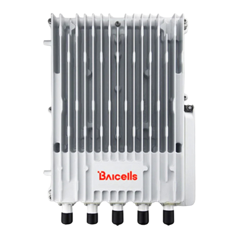
Figure 1-2: Network Structure ................................................................................................... 6
Figure 2-1: LEDs and Interfaces ................................................................................................. 9
Figure 2-3: CloudCore Login Page ............................................................................................ 11
Figure 3-1: Installation Process................................................................................................ 11
Figure 3-3: Mark and Drill the Holes........................................................................................ 12
Figure 3-3: Install Expansion Pipes and Screws........................................................................12
Figure 3-4: Fix the eNB to the Bracket ..................................................................................... 12
Figure 3-5: Screw Location on the Bracket............................................................................... 13
Figure 3-6: PWR Power Supply, OPT Backhaul Configuration .................................................. 14
Figure 3-7: PWR Power Supply, WAN/PoE+ Backhaul Configuration ....................................... 14
Figure 3-8: WAN/PoE+ and Power Supply Backhaul Configuration.......................................... 15
Figure 3-9: Check LEDs............................................................................................................. 15
Figure 3-10: GUI Login ............................................................................................................. 16
Figure 3-11: Home Page (Example is a lab Neutrino-430) ....................................................... 17
Figure 3-12: Configuration Flow .............................................................................................. 18
Figure 3-13: WAN/LAN ............................................................................................................ 19
Figure 3-14: LGW ..................................................................................................................... 20
Figure 3-15 LGW = Router........................................................................................................ 21
Figure 3-16: Static Routing ...................................................................................................... 21
Figure 3-17: Management Server ............................................................................................ 22
Figure 3-18: Quick Setting ....................................................................................................... 24
Figure 3-19: Carrier Setting...................................................................................................... 25
Figure 3-20: Cell Status (eNB GUI) ........................................................................................... 26
Figure 3-21: Cell Status (OMC)................................................................................................. 27
List of Tables
Table 2-1: Installation Tools ....................................................................................................... 9
Table 2-2: LEDs ........................................................................................................................ 10
Table 2-3: Interfaces ................................................................................................................ 10
Table 2-4: Environment Specifications..................................................................................... 10
Table 3-1: Internet/WAN .........................................................................................................19
Table 3-2: LGW ........................................................................................................................ 20
Table 3-3: Static Routing .......................................................................................................... 22
Table 3-4: Management Server ............................................................................................... 23
