Nova430e Outdoor 4x250mW Two-Carrier TDD eNodeB Installation Guide
5
List of Figures
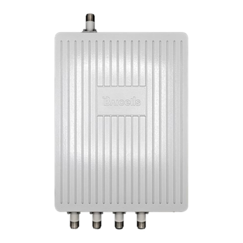
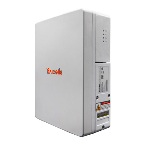
Figure 1-1: Nova430e eNB ............................................................................................................................ 7
Figure 1-2: Network Structure ...................................................................................................................... 7
Figure 2-1: Pack Out....................................................................................................................................10
Figure 2-2: LEDs and Interfaces...................................................................................................................12
Figure 2-3: Weatherproofing ...................................................................................................................... 14
Figure 2-4: Weatherproofing GPS Antenna.................................................................................................14
Figure 2-5: CloudCore Login Page ............................................................................................................... 15
Figure 3-1: Installation Process Overview...................................................................................................15
Figure 3-2: GPS Installation Requirements ................................................................................................. 16
Figure 3-3: GPS Antenna Installation ..........................................................................................................17
Figure 3-4: Pre-assembled Brackets............................................................................................................17
Figure 3-5: Omega Clamps ..........................................................................................................................18
Figure 3-6: Attach Bracket to Pole............................................................................................................... 18
Figure 3-7: Attach eNB to Bracket...............................................................................................................19
Figure 3-8: Completed Attachment.............................................................................................................19
Figure 3-9: Mark and Drill Holes .................................................................................................................20
Figure 3-10: Attach With Expansion Bolts...................................................................................................20
Figure 3-11: Attach eNB to Bracket.............................................................................................................21
Figure 3-12: Pole Grounding ....................................................................................................................... 23
Figure 3-13: Grounding Screws ...................................................................................................................24
Figure 3-14: Connecting Cables and Grounding Screws ............................................................................. 24
Figure 3-15: Check LEDs ..............................................................................................................................25
Figure 3-16: GUI Login................................................................................................................................. 26
Figure 3-17: Home Page.............................................................................................................................. 27
Figure 3-18: Configuration Flow.................................................................................................................. 28
Figure 3-19: WAN/LAN/VLAN...................................................................................................................... 29
Figure 3-20: LAN Config Tab........................................................................................................................ 30
Figure 3-21: LGW......................................................................................................................................... 32
Figure 3-22: LGW = Router.......................................................................................................................... 33
Figure 3-23: Static Routing.......................................................................................................................... 34
Figure 3-24: Management Server ............................................................................................................... 35
Figure 3-25: Quick Setting........................................................................................................................... 38
Figure 3-26: Carrier Setting.........................................................................................................................39
Figure 3-27: Reboot..................................................................................................................................... 39
Figure 3-28: Cell Status (eNB GUI) ..............................................................................................................40
Figure 3-29: Cell Status (OMC)....................................................................................................................40
Figure 3-30: OMC Display Settings.............................................................................................................. 41
