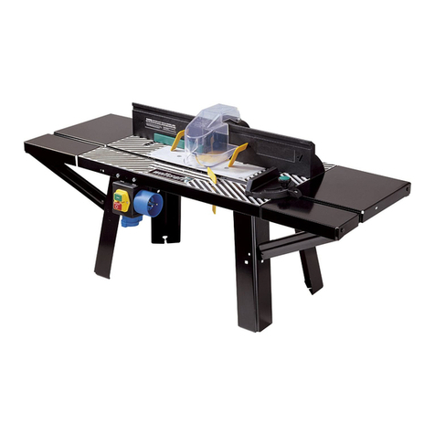
Baileigh WR-32 User manual

OPERATOR’S
MANUAL
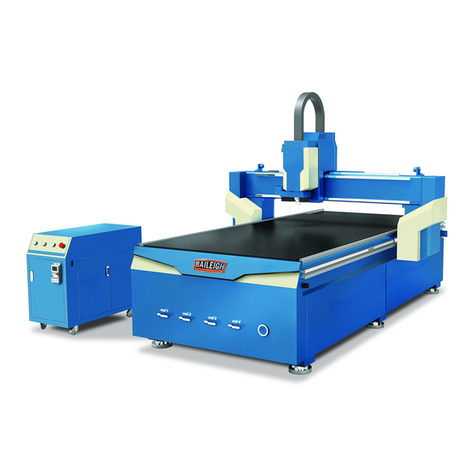
WOOD ROUTER TABLE
MODEL: WR-32
REPRODUCTION OF THIS MANUAL IN ANY FORM WITHOUT WRITTEN APPROVAL OF BAILEIGH INDUSTRIAL
HOLDINGS LLC, IS PROHIBITED. Baileigh Industrial Holdings LLC, does not assume and hereby disclaims any
liability for any damage or loss caused by an omission or error in this Operator’s Manual, resulting from accident,
negligence, or other occurrence.
Baileigh Industrial Holdings LLC,
P.O. Box 531
Manitowoc, WI 54221-0531
Phone: 920.684.4990
Fax: 920.684.3944
© 2020 Baileigh Industrial Holdings LLC
Rev. 05/2020

Table of Contents
MENU TREE...................................................................................................................1
CAUTIONS .....................................................................................................................2
1. Local Files ...............................................................................................................2
2. USB Files.................................................................................................................2
3. Operations...............................................................................................................3
4. Oper Param.............................................................................................................5
5. Mfr Param................................................................................................................ 9
6. Param Upkeep....................................................................................................... 14
7. System Upkeep.....................................................................................................14
8. Diagnosis............................................................................................................... 15

1
1
MENU TREE
The normal operation screen will display is a combination of rows and columns.
X, Y, and Z are each in a row with their coordinate locations relative to the last set workpiece
coordinate. The right or 3rd column is a display of the active operating conditions and settings.
When the machine is not moving it will display “Idle”. When it is being moved or running a
program, it will display “Run”.
The next row down will display the Spindle status. SOff = Spindle Off. When the spindle is
running, this will display from 0S to S7 depending upon the operator’s settings. These steps or
gears are the relative rpm that the spindle will be turning at.
Pressing the “Shift” key will change between “Jog” or “Stepping”. This will change the movement
of the axises from continues as long as the axis key is pressed to moving a specific distance
each time the axis key is pressed.
1X
0.000
Idle
1Y
0.000
SOff
1Z
11.000
Slow
Jog
100%
Pressing the OK key will change to the parameters screen for the operation being performed.
Using the up or down arrow keys will move the cursor around the screen to allow for values to
be edited as needed. Press ESC to return to the Operating screen. Pressing the
MSpd
8000/
3000
StepXY
0.100
StepZ
0.100
File
T1.NC
The following is a table of the options that are listed in the full system menu. While most options
are available and active, some are not. Those options under the Mfg Parameter require a
password to enter to help prevent damage to the material and machine.
When a menu item is highlighted, use the OK key to enter the next level, or accept any
changes. Use the ESC to move back a screen or cancel any changes.
Some of the basic parameters from the menu are listed below. DO NOT make changes to the
parameters if unsure of the outcome of the change. Some changes can damage the machine or
the workpiece if changed incorrectly.

2
2
CAUTIONS
1. Do Not expose to static electrical charges.
2. Do Not use this product in strong magnetic fields or areas of interference.
3. Do Not Pull out U Disk while it is running a file.
4. Protect it from water, moisture, dust, and heat.
5. Protect it from metal contaminates getting into the cover.
6. Do Not remove cover. There are no user serviceable components inside.
7. Plug U disk and other cables gently into the device.
•USE CARE. These settings are normally adjusted by the operator to get the best
cut possible. Take notes and if possible practice on scrap material to get the settings which
will produce the best results.
•STOP! These settings are not normally changed. DO NOT change these settings
unless asked to by an authorized Baileigh Industrial service technician.
1. Local Files
1
Local Files
Program files saved
to memory
2. USB Files
2
USB Files
Program files saved
to USC Disk
NOTICE: While some of these settings are intended to be adjusted by the operator to tune
the operation to the material and cut being performed, other settings are not to be changed
by the operator. If you are unsure of the effect a change to a setting will have on the
performance of the table, do not make the change.
DAMAGE DUE TO INCORRECT SETTING WILL NOT BE COVERED UNDER
WARRANTY.

3
3
3. Operations
STOP! The parameters shown in the OPERATIONS menu below should only
be changed by an experienced operator. Failure to do so may result in incorrect machine
motions and possible machine damage. Take notes and if possible practice on scrap material
to get the settings which will produce the best results.
3
Operations
1 Back REF Point
1 All Home
2 Z Home
3 X Home
4 Y Home
2 Rect Machining
1 Params Settings
EngrDpth 0.100
EachDpth 0.100
ToolDia 3.000
NoseGap 2.000
Height 100.000
Width 100.000
X Init 0.000
Y Init 0.000
Mode Horiz. Mill
------Load Now--
2 Load The Last
Will start the last
program
3 Select Line No
Total : 0
StartLi 0
EndLine 0
-----Execute Now--
4 Machining Info
Time: 0:0:5
X: 109 109
Y: 3088 3088
Z: 0 0
5 Park MCS Site
1 Park Mode
Not move
To park site
To WCS Origin
[OK]Select
2 Park Site
1 Input Site
Input park site
X : 109.500
Y : 855.000
Z : -10.000
2 Select Site
Current Site OK
Not ESC
6 Select WCS
G54 WCS
G55 WCS
G56 WCS
G57 WCS

4
4
G58 WCS
G59 WCS
Select by [OK] key
7 Array Process
File <File Name>
Rows 2
Columns 2
RowSpace 50.00
ColSpace 50.00
Delay 50
----Load Now--
8 Origin List
1:X 0.00 Y 0.00 Z 0.00
2:X 0.00 Y 0.00 Z 0.00
3:X 0.00 Y 0.00 Z 0.00
4:X 0.00 Y 0.00 Z 0.00
5:X 0.00 Y 0.00 Z 0.00
6:X 0.00 Y 0.00 Z 0.00
7:X 0.00 Y 0.00 Z 0.00
8:X 0.00 Y 0.00 Z 0.00
①Save②LD③CDel
9 Nearby Process
Will start the last
program

5
5
4. Oper Param
STOP! The parameters shown in the OPER PARAM menu below should only
be changed by an experienced operator. Failure to do so may result in incorrect machine
motions and possible machine damage. Take notes and if possible practice on scrap material
to get the settings which will produce the best results.
4
Oper Param
1 G00 speed
5500.000mm/min
2 Gxx Speed
5000.000mm/min
3 Back REF First
Yes
4 Lifts on Pause
5.000mm
5 Offset
1 PublicOffset
PublicOffset
X Axis: 0.000
Y Axis: 0.000
Z Axis: 0.000
2 Work Offset
1 G54 Offset
G54 Offset
X Axis: 0.000
Y Axis: 0.000
Z Axis: 0.000
2 G55 Offset
G55 Offset
X Axis: 0.000
Y Axis: 0.000
Z Axis: 0.000
3 G56 Offset
G56 Offset
X Axis: 0.000
Y Axis: 0.000
Z Axis: 0.000
4 G57 Offset
G57 Offset
X Axis: 0.000
Y Axis: 0.000
Z Axis: 0.000
5 G58 Offset
G58 Offset
X Axis: 0.000
Y Axis: 0.000
Z Axis: 0.000
6 G59 Offset
G59 Offset
X Axis: 0.000
Y Axis: 0.000
Z Axis: 0.000
6 CycleProcess
1 Cycle Process
No
Spec.:
Enable cycle process
Value: No
Unit:
Enable cycle
process
●Yes
►No
2 Cycle Times
2
Spec.:
Cycle times
Value: 2

6
6
Unit:
3 Cycle Interval
0ms
Spec.:
Interval of cycle
process
Value: 0
Unit: ms
SOff In Interval
No
Spec.:
SPDL off in the
interval
Value: No
Unit:
Enable cycle
process
●Yes
►No
7 G73_G83Retrac
0.000mm
Spec.:
G73_G83 retract
distance
Value: 0.000
Unit: mm
8 Ignore F Code
Yes
Spec.:
Ignore F code
Value: Yes
Unit:
Ignore F code
►Yes
●No
9 Ignore S Code
Yes
Spec.:
Ignore S code
Value: Yes
Unit:
Ignore S code
►Yes
●No
10 SpindleStop
1 SOff at Pause
Yes
Spec.:
Spindle off when
pause
Value: Yes
Unit:
Spindle off when
pause
►Yes
●No
2 SOff at Stop
Yes
Spec.:
Spindle off when stop
Value: Yes
Unit:
Spindle off when
stop
►Yes
●No
3 SOff at End
Yes
Spec.:
Spindle off when end
Value: Yes
Unit:
Spindle off when
finish
►Yes
●No
11 Ratio ON MANU
Yes
Spec.:
Ratio on when MANU
mode
Value: Yes
Unit:
Ratio on when
MANU mode
►Yes
●No
DXF Params
1 Lifting Height
1.000mm
Spec.:
Lifting height at G00
Value: 1.000
Unit:mm
2 Process Depth
-1.000mm
Spec.:
Process depth
Value: -1.000
Unit:mm
3 FirstPointAs0
Yes
Spec.:
First point as zero
First point as
zero

7
7
Value: Yes
Unit:
►Yes
●No
4 Shape Process
No
Spec.:
Process shape
separately
Value: No
Unit:
Process shape
separately
●Yes
►No
5 Bottom Process
No
Spec.:
Enable bottom
machining
Value: No
Unit:
Enable bottom
machining
●Yes
►No
Metric Size
No
Spec.:
Adopt metric size
Value: No
Unit:
Adopt metric size
●Yes
►No
13 Eng Params
1 Lifting Height
1.000mm
Spec.:
Lifting height at G00
Value: 1.000
Unit:mm
2 ToolChangeTip
Yes
Spec.:
Enable tool change
tip
Value: Yes
Unit:
Enable tool
change tip
►Yes
●No
3 Cycle Times
1
Spec.:
Cycle process times
Value: 1
Unit:
4 Deep Hole Mode
0
Spec.:
0: Recip chip;
1: HS Recip chip
Value: 0
Unit:
5 Retract Amount
1.000mm
Spec.:
Retract amount
Value: 1.000
Unit: mm
6 Select ToolNo.
Yes
Spec.:
Process per tool No.
Value: Yes
Unit:
Process per tool
No.
►Yes
●No
14 Plt Params
1 Lifting Height
5.000mm
Spec.:
Lifting height
Value: 5.000
Unit: mm
2 Plt Unit
40.000
Spec.:
Plt unit
Value: 40.000
Unit:
3 Tool step
0.025mm
Spec.:
Tool step

8
8
Value: 0.025
Unit: mm
4 Process Depth
-1.000mm
Spec.:
Process depth
Value: -1.000
Unit: mm
15 Tool Change
1 ATC Capacity
1
Spec.:
Tool magazine
capacity
Value: 1
Unit:
2 CurrentToolNo.
1
Spec.:
Set current tool No.
Value: 1
Unit:
3 Tool Offset
1 Tool1
Tool Offset 1
X Axis: 0.000
Y Axis: 0.000
Z Axis: -0.000
4 ToolChangeTip
No
Spec.:
Enable tool change
tip
Value: No
Unit:
Enable tool
change tip
●Yes
►No
5 Cali Coor
1 X Cali Coor
00.000mm
Spec.:
X MEC coor of
cali block
Value: 00.000
Unit: mm
2 Y Cali Coor
00.000mm
Spec.:
Y MEC coor of
cali block
Value:00.000
Unit: mm
3 Z Cali Coor
-1.000mm
Spec.:
Z MEC coor of
cali block
Value:-1.000
Unit: mm
16 ProcessEndTip
No
Spec.:
Red lamp after
process
Value: No
Unit:
Red lamp after
process
●Yes
►No
17 Cali. Height
1.000mm
Spec.:
Height after Calibrate
Tool
Value: 1.000
Unit: mm

9
9
5. Mfr Param
•STOP! These settings are not normally changed. DO NOT change these
settings unless asked to by an authorized Baileigh Industrial service technician.
5
Mfr Param
Password =
33587550
1. Velocity
1. Decel. Dist.
10.000mm
Spec.:
Decel. distance
Value: 10.000
Unit: mm
2. Approach Speed
400.000mm/min
Spec.:
Approach speed
Value: 400.000
Unit: mm/min
3. Run Acc.
500.000mm/s^2
Spec.:
The maximum linear
Acc. when machining
Value: 500.000
Unit: mm/s^2
4. Dry Run Acc.
500.000mm/s^2
Spec.:
The maximum linear
Acc. when
positioning
Value: 500.000
Unit: mm/s^2
5. Max.Turn Acc.
1000.000mm/s^2
Spec.:
Maximum. turn acc.
Value: 1000.000
Unit: mm/s^2
6. Jerk
150000.000mm/s^3
Spec.:
Jerk
Value: 150000.000
Unit: mm/s^3
7. Max Speed
*Max speed of axis
(mm/min)
X Axis: 10000.000
Y Axis: 10000.000
Z Axis: 5000.000
8. ShortSegSpdLmt
Yes
Spec.:
Enable short
Seg.SpdLmt
NOTICE: While some of these settings are intended to be adjusted by the operator to tune
the operation to the material and cut being performed, other settings are not to be changed
by the operator. If you are unsure of the effect a change to a setting will have on the
performance of the table, do not make the change.
DAMAGE DUE TO INCORRECT SETTING WILL NOT BE COVERED UNDER
WARRANTY.

10
10
Value: Yes
Unit:
9. SpdLmt Length
0.500mm
Spec.:
Length of short
Seg.SpdLmt
Value: 0.500
Unit:mm
10. Z Down Option
0
Spec.:
0:Not 1:Z single
2:XYZ all
Value: 0
Unit:
11. ZPlungeCutSpd
300.000mm/min
Spec.:
Plunge Spd along Z
Value: 300.000
Unit: mm/min
12. RefCirRadius
5.000mm
Spec.:
Reference circle
radius
Value: 5.000
Unit: mm
13. RefCirSpeed
3000.000mm/min
Spec.:
Reference circle
speed
Value: 3000.000
Unit: mm/min
14. Jump Speed
0.000mm/min
Spec.:
Jump speed
Value: 0.000
Unit: mm/min
15. LookAheadDis
0.000mm
Spec.:
Look ahead distance
Value: 0.000
Unit: mm
2. AxisOutputDir
*Axis output dir.
X Axis: Positive
Y Axis: Positive
Z Axis: Positive
3. Pulse Equiv.
* P Equiv (mm/p)
X Axis: 0.0050000
Y Axis: 0.0050000
Z Axis: 0.0025000
4. MachineStroke
1. StrkUpperLmt
StrkUpperLmt (mm)
X Axis: 665.000
Y Axis: 930.000
Z Axis: 0.000
2. StrkLowerLmt
StrkLowerLmt (mm)
X Axis: 0.000
Y Axis: 0.000
Z Axis: -100.000
5. ChangeStroke
1. StrkUpperLmt
StrkUpperLmt (mm)
X Axis: 665.000

11
11
Y Axis: 930.000
Z Axis: 0.000
2. StrkLowerLmt
StrkLowerLmt (mm)
X Axis: 0.000
Y Axis: 0.000
Z Axis: -100.000
6. REF.PointSet
1. REFP Speed
Speed (mm/min)
X Axis: 2800.000
Y Axis: 2800.000
Z Axis: 1800.000
2. REFP Dir
Homing direction
X Axis: Negative
Y Axis: Negative
Z Axis: Positive
3. Retract Dist
1. X Retract Dist
2.000mm
Spec.:
Retract distance
of X
Value: 2.000
Unit: mm
2. Y Retract Dist
2.000mm
Spec.:
Retract distance
of Y
Value: 2.000
Unit: mm
3. Z Retract Dist
-2.000mm
Spec.:
Retract distance
of X
Value: -2.000
Unit: mm
7. Spindle Set
1. Spindle Gears
8
Spec.:
* Spindle gears
Value: 8
Unit:
2. ON/OFF Delay
5000ms
Spec.:
Spindle ON/OFF
delay
Value: 5000
Unit:ms
3. Initial Gear
5
Spec.:
* Spindle initial gear
Value: 5
Unit:
4. Max Spdl Speed
18000r/min
Spec.:
* Max spindle speed
Value: 18000
Unit:r/min
8. Y Rotaryaxis
1. YasRotaryAxis
No
Spec.:
* Y as rotary axis
Value: No
Unit:
2. Rotary Y Pulse
0.00600drg/p
Spec.:
* Rotary Y pulse

12
12
equivalent
Value: 0.00600
Unit:deg/p
3. mm As Unit
No
Spec.:
Use mm as unit
Value: No
Unit:
4. Rev.WorkRadius
10.000mm
Spec.:
* Rotary workpiece
radius
Value: 10.000
Unit:mm
5. Rotary Takeoff
0.291rad/s
Spec.:
Takeoff speed of
rotary Y
Value: 0.291
Unit:rad/s
6. Rotary Y Acc.
6.981rad/s^2
Spec.:
Rotary Y acceleration
Value: 6.981
Unit:rad/s^2
7. Max RotaryVel.
30.000r/min
Spec.:
Max. Vel. of rotary Y
Value: 30.000
Unit:r/min
9. Compensation
ScrewErrorComp
No
Spec.:
* Enable screw error
compensation
Value: No
Unit:
EnableBacklash
No
Spec.:
* Enable backlash
Value: No
Unit:
AxisBacklash
* Backlash (mm)
X Axis: 0.000
Y Axis: 0.000
Z Axis: 0.000
10. CaliThickness
10.000mm
Spec.:
Touch CAD thickness
Value: 10.000
Unit: mm
11. Algorithm
1
Spec.:
0: Triangle, 1:S_Type,
2:Trapezoid
Value: 1
Unit:
12. Arc Increment
Yes
Spec.:
Enable incremental
mode
Value: Yes
Unit:

13
13
13. Arc Tolerance
2.000mm
Spec.:
Arc Radius Tolerance
Value: 2.000
Unit:mm
14. Forward Seg
50
Spec.:
Prospect. Segments
Value: 50
Unit:
15. Sign of BKREF
Yes
Spec.:
Cancel REF Sign after
E-stop
Value: Yes
Unit:
16. Safety Height
10.000mm
Spec.:
* Safety height
Value: 10.000
Unit:mm
17. Lube
1. EnableAutoLube
No
Spec.:
Open auto lubrication
Value: No
Unit:
2. Time Interval
5000s
Spec.:
Interval between two
lubes
Value: 5000
Unit:sec
3. Duration
5s
Spec.:
Duration for each
lubet
Value: 5
Unit:sec
18. G00 Feed 100%
Yes
19. SmoothingTime
0.000s
20. Corner Option
0
21. Corner Toler
0.100mm
22. Control Cycle
No
23. SoftLimitTime
0.500s
24. User Param
1. User Param 2
Yes
Spec.:
User PARAM2: user
param 2
Value: Yes
Unit:

14
14
6. Param Upkeep
STOP! The parameters shown in the PARAM UPKEEP menu below should
only be used by an experienced operator. Failure to do so may result in incorrect
machine motions and possible machine damage.
6
Param Upkeep
1 Backup Params
OK, or ESC
2 Restore Backup
OK, or ESC
3 Factory Params
OK, or ESC
4 Export Params
OK, or ESC
5 Import Params
OK, or ESC
6 Import ErrData
OK, or ESC
7. System Upkeep
STOP! The parameters shown in the SYSTEM UPKEEP menu below should only be
used by an experienced operator. Failure to do so may result in incorrect machine
motions and possible machine damage.
7
System Upkeep
1 Language
1. Chinese
2 English
OK, or ESC
2 Export Log
OK, or ESC
3 System Update
OK, or ESC
4 Register
Enter Reg. Code
5 Help
Spec.: Help Message
Show Delay
Value: 1
Unit:S
6 Reboot
OK, or ESC
7 Exit
OK, or ESC
8 Delete Log
OK, or ESC
9 Disk Space
Disk Space Left
220M/239M

15
15
10 Delete Info
OK, or ESC
11 Modify Code
Old PWD:
New PWD:
Confirm:
--------------Modify---
8. Diagnosis
STOP! The parameters shown in the DIAGNOSIS menu below should only be used
by an experienced operator. Failure to do so may result in incorrect machine motions
and possible machine damage.
8
Diagnosis
1 System Info
1. Software Ver.
Software Version
NK105G3_20_72f2
2. Card No.
Card No.
WHNC-0105-
TQDHW-17BF
3. Remaining Time
Remaining Time
Limitless
4. Register Times
Registered Times
1
2 Port List
IN GX01 º N
IN GX02 º N
IN GX03 º N
IN GX04 º N
IN GX05 º N
IN GX06 º N
IN GX07 º N
IN GX08 ºN
IN GX09 º N
IN GX10 º N
IN GX11 ºN
IN GX12 ºN
IN GX13 º N
IN GX14 º N
IN GX15 º N
IN GX16 º N
IN ALAM º N
OUT GY13 º N
OUT GY14 º N
OUT GY15 º N
OUT GY16 º N
OUT GY17 º N
OUT GY18 º N
OUT GY19 º N
OUT GY20 º N
3 Keypress Diag
Press a key:

16
16
4 Inport Diag
0 1 2 3 4 5 6 7
º º º º º º º •
8 9 A B C D E F
º º • • º º º º
5 Outport Diag
0 1 2 3 4 5 6 7
º º º º º º º º
Will cycle through
each out put.
6 LED Diag
Press K1 key to test
LED
NOTES

17
17
NOTES

18
18
BAILEIGH INDUSTRIAL HOLDINGS LLC
1625 DUFEK DRIVE MANITOWOC,WI 54220
PHONE:920. 684. 4990 FAX:920.684. 3944
www.baileigh.com
BAILEIGH INDUSTRIAL HOLDINGS LTD. UNIT DSWIFT POINT
SWIFT VALLEY INDUSTRIAL ESTATE,RUGBY
WEST MIDLANDS,CV21 1QH UNITED KINGDOM
PHONE:+44 (0)24 7661 9267 FAX:+44 (0)24 7661 9276
WWW.BAILEIGH.CO.UK
Other manuals for WR-32
1
This manual suits for next models
1
Table of contents
Other Baileigh Wood Router manuals