Balmar Centerfielder II User manual

INSTALLATION AND OPERATION MANUAL
Introduction
Designed for use in application requiring balanced charge control from
two alternators and two regulators on twin engines, the Centerelder
II: CFII-12/24 makes it possible to utilize the combined output of both
alternators to supply optimized charging to a single large battery bank.
By monitoring the ignition and eld voltages at port and starboard
regulators, the CFII-12/24 determines when both engines are running,
and directs eld current from the master (starboard) regulator to both
alternators. By controlling both alternators with the same eld source,
the CFII-12/24 ensures that alternators can work together to ensure
optimal charging at a single large battery bank.
Safety Considerations
1. Always disconnect your battery banks and
ensure that switches are “OFF” prior to
installing your regulator.
2. Remove loose-tting clothing or jewelry,
which could become entangled in your
motor or other machinery prior to installing
regulator.
3. Wear ANSI-approved safety eye-wear and
protective gear.
4. DO NOT attempt to modify the regulator.
Modications could result in damage to
your charging system, and will void your
warranty.
5. DO NOT attempt installation if you are tired
or fatigued.
6. Ensure that the engine has cooled before
initiating installation.
7. DO NOT attempt regulator installation while
using alcohol or medication that could
impair your judgment or reaction time.
8. Always use the right tool for the job.
Improper tool use may damage regulator
or your vessel, and could result in personal
injury.
9. Take time to read the manual. Equipment
damage and possible injuries may result
from an incomplete understanding of the
installation and operation of the MC-612-
DUAL regulator. If you are unfamiliar with
marine electrical systems, consult with a
licensed marine electrician.
Centerelder II
CFII-12/24
Introduction 1 Regulator Terminal Layout 3-4
Safety Considerations 1 12 Volt Wire Diagram 5
CFII-12/24 Installation 2 24 Volt Wire Diagram 6
Unpacking Box 2 Warranty 7
Locate/Mount Regulator 2
Table of Contents

2
CAUTION: The following instructions are intended for use by experienced marine electrical installers.
If you are not experienced at installing electrical system components, we recommend the use of a
qualied marine electrical technician.
CFII-12/24 Installation
The following information is intended to provide the installer with the basic information required to complete installation. This
section of the installation manual will deal with mounting and wiring connections.
Unpacking the Box
Your Max Charge CFII-12/24 regulator kit is packaged with the following items:
•Centerelder II: CFII-12/24
•Collection of wiring terminal connectors
•(2) fused 12-gauge RED wires required to replace the standard
•14-gauge RED power wires in the Max Charge regulator’s wiring harness
•CFII-12/24 Quick Start Guide
Installation
The Centereldr II is easy to install. You will nd, included with the Centerelder II, a collction of wiring terminal connectors
as well as two fused 12-gauge RED wires required to replace the standard 14-gauge RED power wires in the Max Charge
regulator’ wiring harnesses.
Use wire size calculation in alternator manual to determine required wire size based on the length of wire run needed to
connect charging system components.
To Install:
1. Disconnect batteries or turn battery switches to the OFF position.
2. Install the CFII 12/24 on a bulkhead or other at surface that’s away from extreme heat or moisture. Typically, the CFII-
12/24 is mounted close to one or the other voltage regulator.
3. Determine the distances and gauges required for wire runs between the CFII-12/24, the Max Charge regulators and the
port and starboard alternators.
4. Connect the supplied wiring connectors to their appropriate wires, as described to the right, and connect to the CFII-12/24,
regulators and alternators as shown.
5. Remove the exiting RED power wires from the Max Charge wiring harnesses and replace with the included, fused RED
12-gauge wires.
6. Re-connect batteries and start engines. Indicator LEDs will light as the CFII-12/24 controls eld output from the regulators
to the two alternators.

3
CFII-12/24 Regulator Terminal Layout
1. PORT REGULATOR FIELD INPUT TERMINAL
2. PORT ALTERNATOR FIELD OUTPUT
TERMINAL
3. PORT “IGNITION ACTIVATED” LED (RED)
4. PORT REGULATOR IGNITION
5. PORT IGNITION INPUT
6. PORT REGULATOR DASH LAMP TERMINAL
7. PORT DASH LAMP TERMINAL
8. PORT “DASH LAMP” LED (RED)
9. GROUND TERMINAL
10. STARBOARD “DASH LAMP: LED (GREEN)
11. STARBOARD REGULATOR DASH LAMP
TERMINAL
12. STARBOARD DASH LAMP TERMINAL
13. COMMUNICATIONS PORT
14. COMMUNICATIONS PORT
15. COMMUNICATIONS PORT
16. STARBOARD IGNITION INPUT
17. STARBOARD REGULATOR IGNITION
18. STARBOARD “IGNITION ACTIVATED” LED
(GREEN)
19. STARBOARD ALTERNATOR FIELD OUTPUT
TERMINAL (MASTER)
20. STARBOARD REGULATOR FIELD INPUT
TERMINAL (MASTER)
21. “COMBINE” LED (AMBER)
6
5 4
7
2
1
8
9
10
3
11
12
13
14
15
16
18
19
20
21
1. PORT REGULATOR FIELD INPUT TERMINAL - Connect Terminal #1 to port voltage regulator’s Field Output
terminal via a user-supplied 12-gauge BLUE wire. A female 1/4” spade terminal is supplied for connection to Terminal #1.
The 12-gauge BLUE wire will replace the regulator’s 14-gauge eld wire.
2. PORT ALTERNATOR FIELD OUTPUT TERMINAL - Connect Terminal #2 to the port alternator’s eld input terminal
via a user supplied 12-gauge BLUE wire. A female 1/4” spade terminal is supplied for connection to Terminal #2. Alternator-
side termination will vary based on alternator, and may require a user-supplied spade or ring terminal connector, depending
on the alternator conguration.
3. PORT “IGNITION ACTIVATED” LED (RED) - Indicates activation of port voltage regulator’s ignition wire. If LED is
illuminated, but the port voltage regulator is inactive, check for voltage at the regulator’s ignition terminal.
4.
5. PORT REGULATOR IGNITION - Connect Terminal #4 to the port voltage regulator’s BROWN ignition wire. A BROWN
14-Gauge user-supplied wire is recommended. A female 1/4” spade terminal is supplied with the Centerelder II.
6. PORT IGNITION INPUT - Connect Terminal #5 to the port engine ignition switch or port engine oil pressure switch.
Terminal #5 must see zero volts when the port engine is turned off, and battery voltage when the port engine is running.
BROWN 14-Gauge user-supplied wire is recommended. A female 1/4” spade terminal is supplied for connection to
Terminal.

4
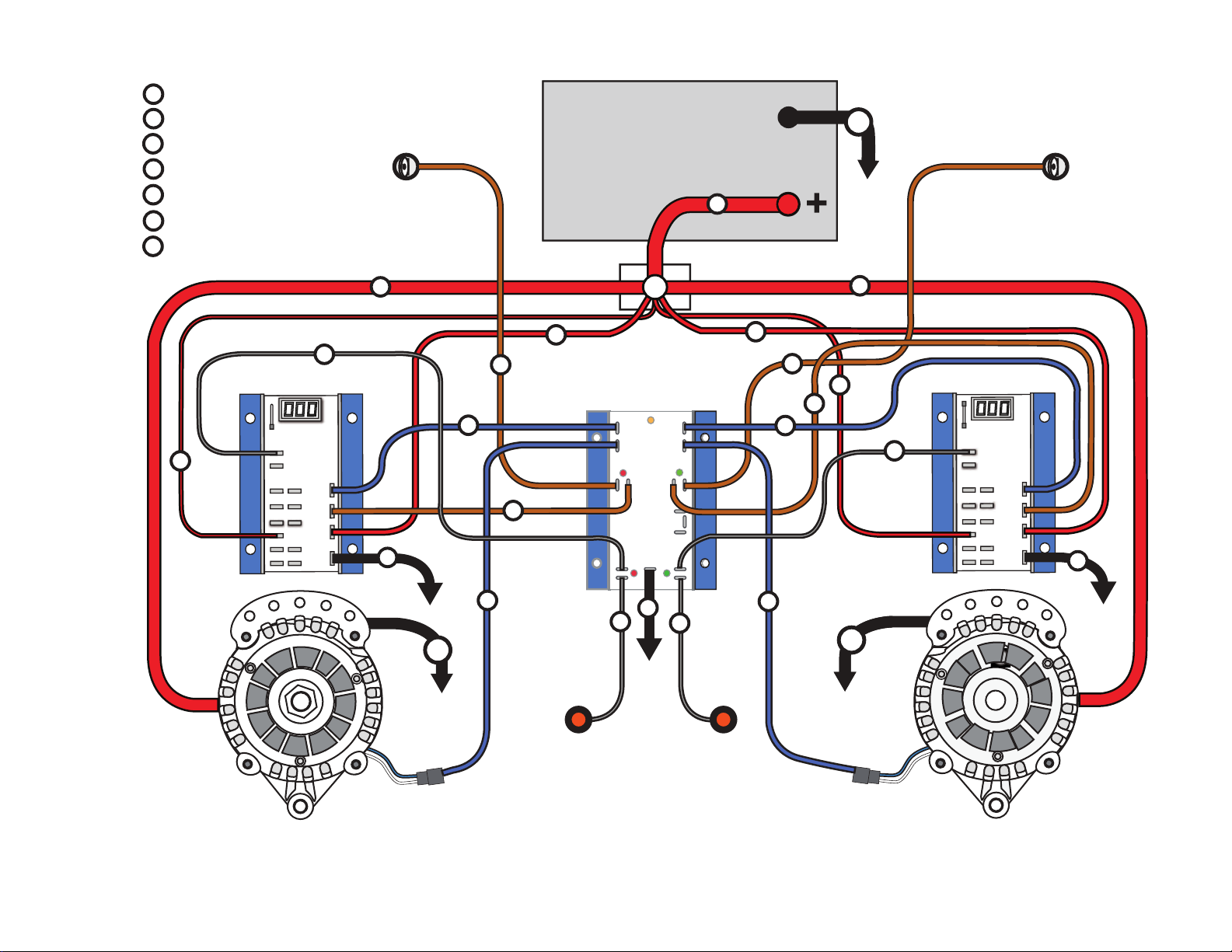
7. PORT REGULATOR DASH LAMP TERMINAL- Connect Terminal #6 to the port voltage regulator’s dash lamp
terminal via a user supplied 16-gauge wire. Female 1/4” spade terminals are supplied for connecting to Terminal #6.
8. PORT DASH LAMP TERMINAL- Connect Terminal #7 to the port dash lamp via a user supplied 16-gauge wire. Female
1/4” spade terminals are supplied for connection to Terminal #7.
9. GROUND TERMINAL - Connect Terminal #9 to system ground via 14-gauge BLACK wire. A female 1/4” spade terminal
is supplied for connection to Terminal #9. Termination to system ground will require a user-supplied spade or ring terminal
connector, depending on the ground location chosen. ALL GROUND CONNECTIONS MUST BE COMMON.
10. STARBOARD “DASH LAMP” LED (GREEN)- Indicates activation of starboard voltage regulator’s Dash Lamp
terminal. Activation of the Dash Lamp may occur as a result of high or low voltage, high alternator or high battery
temperature. If LED is illuminated, inspect the starboard voltage regulator long display for advisory codes.
11. STARBOARD REGULATOR DASH LAMP TERMINAL- Connect Terminal #11 to the starboard voltage regulator’s
dash lamp terminal via a user supplied 16-gauge wire. Female 1/4” spade terminals are supplied for connection to Terminal
#11.
12. STARBOARD DASH LAMP TERMINAL- Connect Terminal #12 to the starboard dash lamp via a user supplied
16-gauge wire. Female 1/4” spade terminals are supplied for connection to Terminal #12, and for connection to the
starboard regulator’s dash lamp.
13. COMMUNICATION PORT- Factory use only.
14. COMMUNICATION PORT- Factory use only.
15. COMMUNICATION PORT- Factory use only.
16. STARBOARD IGNITION INPUT- Connect Terminal #16 to the starboard ignition switch or starboard engine oil pressure
switch. Terminal #16 must see zero volts when the starboard engine is turned off, and battery voltage when the starboard
engine is running. BROWN 14-Gauge user-supplied wire is recommended. A female 1/4” spade terminal is supplied for
connection to Terminal #16.
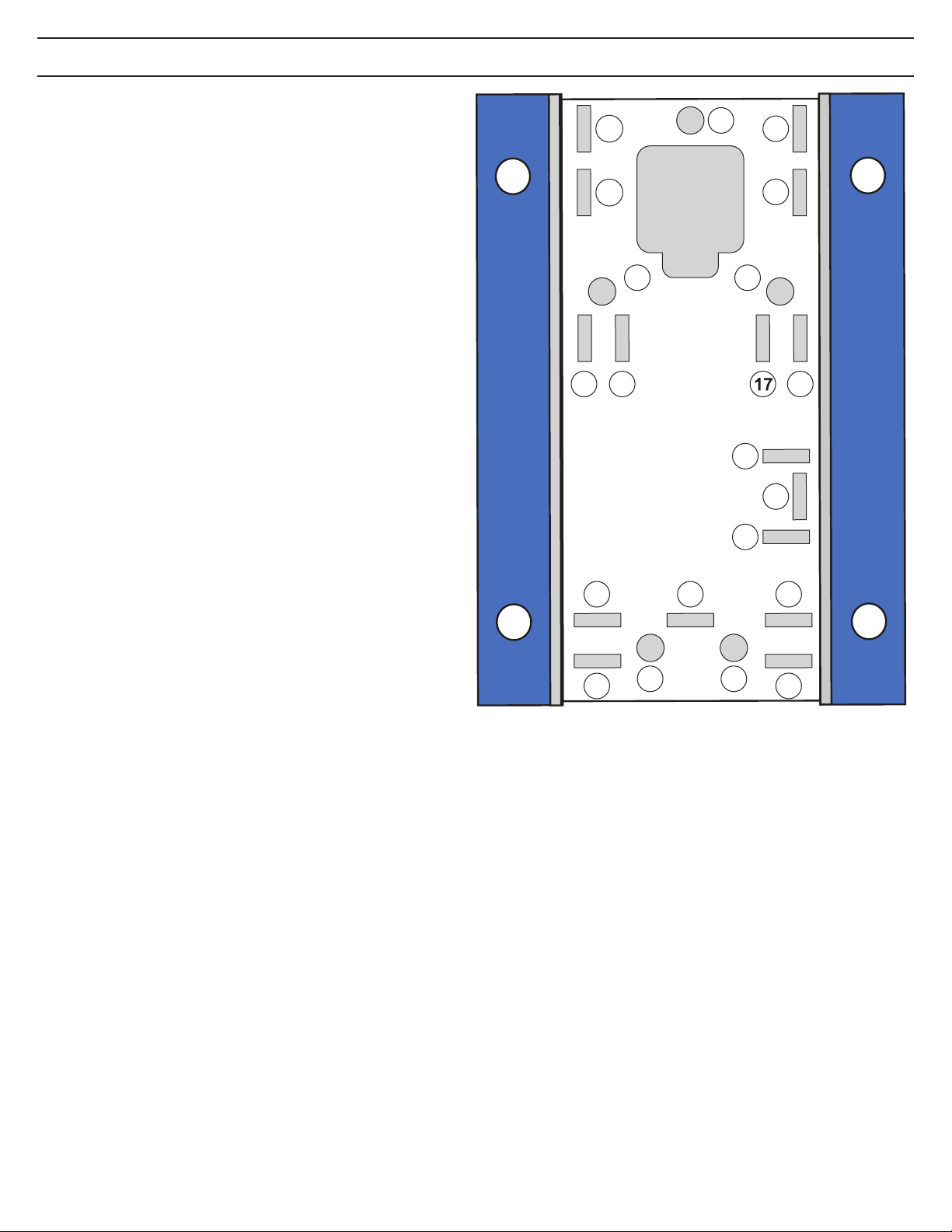
17. STARBOARD REGULATOR IGNITION- Connect Terminal #17 to the starboard voltage regulator’s BROWN ignition
wire. A BROWN ignition wire. A BROWN 14-Gauge user-supplied wire is recommended. A female 1/4” spade terminal is
supplied for connection to Terminal #17.
18. STARBOARD “IGNITION ACTIVATED” LED (GREEN)- Indicates activation of starboard voltage regulator’s ignition
wire. If LED is illuminated, but the starboard voltage regulator is inactive, check for voltage at the regulator’s ignition
terminal.
19. STARBOARD ALTERNATOR FIELD OUTPUT TERMINAL (MASTER)- Connect Terminal #19 to the starboard
alternator’s eld input terminal via a user supplied 12-Gauge BLUE wire. A female 1/4” spade terminal is supplied for
connection to Terminal #19. Alternator-side termination will require a user-supplied spade or ring terminal connector,
depending on the alternator conguration.
20. STARBOARD REGULATOR FIELD INPUT TERMINAL (MASTER)- Connect Terminal #20 to starboard voltage
regulator’s Field Output terminal via a user-supplied 12-Gauge BLUE wire. A female 1/4” spade terminal is supplied for
connection to Terminal #20. The 12-Gauge BLUE wire will replace the regulator’s 14-Gauge eld wire.
21. “COMBINE” LED (AMBER)- Indicates activation of port and starboard alternators and voltage regulators. The CFII -
12/24 will continue to supply balanced eld current to both port and starboard alternators when the LED is activated.

Centerfielder II Installation - 12-Volt System
STBD.
IGNITION
SWITCH
PORT
IGNITION
SWITCH
G
HOUSE BATTERY
BANK
PORT ALTERNATOR
G
STARBOARD ALTERNATOR
G
CENTERFIELDER
POWER
POST
STARBOARD
REGULATOR
PORT REGULATOR
I
F
G
D
P
S
B+
DASH LAMP WIRE
REGULATOR FIELD WIRE
REGULATOR IGNITION WIRE
GROUND WIRE
REGULATOR POWER WIRE
POSITIVE BATTERY CABLE
VOLTAGE SENSE WIRE
DASH LAMP DASH LAMP
I
I
I
I
F
FF
F
B+ B+
B+
S
S
PP
D
D
D
D
G
GG
SLAVE MASTER

PORT
MAX CHARGE
SLAVE
STARBOARD
REGULATOR
MASTER
Centerfielder II Installation - 24-Volt System
STBD.
IGNITION
SWITCH
PORT
IGNITION
SWITCH
G
HOUSE BATTERY
BANK
PORT ALTERNATOR
G
STARBOARD ALTERNATOR
G
CENTERFIELDER
POWER
POST
I
F
G
D
P
ST
B+
DASH LAMP WIRE
REGULATOR FIELD WIRE
REGULATOR IGNITION WIRE
GROUND WIRE
REGULATOR POWER WIRE
POSITIVE BATTERY CABLE
STATOR WIRE
DASH LAMP DASH LAMP
II
F
F
B+ B+
B+
PP
D
D
G
GG
F
I
F
D
I
D
ST
ST
Check out the collection of marine batteries and power we offer.
This manual suits for next models
1
Table of contents
Other Balmar Batteries Charger manuals