Bang & Olufsen beosound 1 2581 User manual

BeoSound 1
Type 2581, 2582, 2583, 2584, 2585, 2586, 2587, 2590
On-site service guide
English, German, French, Italian, Spanish, Danish, Dutch, Japanese
This On-site service guide must be
returned with the defective parts/
back-up suitcase !

1.1
Brief operation guide
Buttons on BeoSound 1
- AERIAL. Press to extend and retract the built-in aerial.
- DELETE is used to delete station settings and to omit CD tracks from playback.
- STORE is used to store radio stations and volume level.
- ln. Use for searching through a CD, for tuning in radio stations and for activating
the AUX socket (press simultaneously).
- STOP. Use in CD playback to pause and stop, for programming Stop timers and
for tuning in radio stations.
- LOAD. Press to open and close the CD compartment.
- lCD n. Press to switch on the CD player. Press to step forwards or backwards
through tracks.
- lRADIO n. Press to switch on the radio. Press to step forwards or backwards
through radio stations.
- uVOLUME r. Press to turn the volume up or down. Press both to mute speakers.
- V. Press to switch BeoSound 1 to standby.
Change display light
- Press and hold STORE. Press uVOLUME rto adjust the display light up or down.
Make and delete Stop Timer
- Press STOP. The minutes is displayed. Press STOP to change the number of minutes.
Wait 5 seconds and the Stop Timer is stored.
Delete a Stop Timer by selecting another source or set the minutes for 00.
Store and delete radio stations
- Search for the station using ln. Press STORE when the requested station is
found. Use lnto change program number if wanted. Press STORE again.
Press DELETE twice to delete the radio station playing.
Set BeoSound 1 in option 0 (no IR) or option 1 (IR) using Beo4
- BeoSound 1 must be in standby. Press and hold Vthen press LIST. Press
LIST (until OPTION) then GO. Press LIST (until A.OPTION) then GO. Press 0or 1.
Further information regarding daily use
- Please refer to the BeoSound 1 Guide for further information regarding daily use.
Connections to BeoSound 1
Brief operation guide
(A)
AUX
- (A). Placement for internal aerial if an external aerial is connected.
- AUX. Connection of external equipment. Press lnsimultaneously to activate.

2.1
Contents, English
#1 Servicing BeoSound 1
#2 Fault flow chart
#3 Test mode
#4 Theft protection
#5 Adjustment after repair of BeoSound 1
#6 Test after repair of BeoSound 1
10.1 Illustrations
11.1 Disassembly/Assembly of BeoSound 1
12.1 Replacement of PCB1, (Main PCB)
13.1 Replacement of PCB2, (SMPS) and PCB3, (Display & IR receiver)
14.1 Replacement of Keyboard Left/Right
15.1 Replacement of PCB4, (Active FM Antenna)
16.1 Replacement of Antenna-loader and speaker units
17.1 Replacement of CD-loader and PCB90, (CD-Mechanism)
18.1 Back-up suitcase
19.1 Survey of modules
Survey of symbols:
Push with finger, in arrow direction
Disconnect internal plug
Connect internal plug
Disconnect mains plug
Connect mains plug
Disconnect antenna or other external plug
Connect antenna or other external plug
Loosen/remove or fasten/install screw
Dashed arrow. Push/pull e.g. PCB, chassis etc. in arrow’s direction
Filled arrow. Refer to page/chapter for more information, e.g. 14.1 PCB4,
if mounted:
Turn to 14.1 PCB4 and remove or install PCB.

2.2 Introduction, English
Warning
Static electricity may destroy the product!
A static-protective field service kit must always be used when replacement of the
modules takes place. Use the ESD mat area for both the new and old modules.
#1 Servicing BeoSound 1
Using the On-site service guide
This On-site service guide will explain and guide you through the repair of the
defective BeoSound 1.
- Follow the guide in order to detect the defective module. Use the replacement
guides which are placed in the back of the on-site service guide when replacing
the module. When replacement is done follow the adjustment and check list to
ensure that the fault has been corrected and that all BeoSound 1 functions are ok.
All illustrations are placed in the back of the guide. An illustration is referred to in
this way: (see ➢X) or ➢X. This refers to ➢X on 10.1 Illustrations.
IMPORTANT: Please read #4 Theft protection before proceeding.
Repair of BeoSound 1
The repair of BeoSound 1 is done by replacing the defect module. This may be
either the Main PCB, the Switch Mode Power Supply (SMPS) or one of the other PCBs.
A complete survey of modules is placed in the back of the guide.
- Before throubleshooting is initiated, let the customer explain and demonstrate the
fault, if possible. Afterwards check:
That the BeoSound 1 is set for the correct option. 1 (IR) or 0 (no IR).
That the mains voltage is connected and switched on and that the red stand by
diode is on.
That an external antenna (if such is being used) is connected correctly.
That the Compact Disc (CD) is correctly inserted and without any severe scratches.
Use the test-CD SBC 444A if necessary. Ensure that tracks 10, 17 and 19 on the
CD are being played correctly.
Use Test mode (TM) and/or fault flow chart to repair
IMPORTANT: BeoSound 1 is in safety mode when stand by diode is flashing and
no source selection is possible: disconnect mains voltage and wait 10 seconds
before reconnecting it. If still in safety mode please note that entering TM can
damage the product.
- If possible turn on BeoSound 1 and enter TM.
Enter TM43 and read out the values.
See #3 Test mode for further information.
STATIC ELECTRICITY
MAY DESTROY THE
PRODUCT

2.3
Introduction, English
- When troubleshooting is initiated please refer to #2 fault flow chart. The fault
should fit into one of the four main groups:
System functionality
Sound
Radio
CD
Disassemble the product in order to gain access to the PCBs inside BeoSound 1.
- If possible then enter TM27 and check error 0. If the fault flow chart and TM27
indicate the same module, replace it.
See #3 Test mode for further information.
Otherwise it might be a good idea to look through the fault flow chart again to
make sure that the conclusion is correct.
- Make the replacement and then check if the fault has been corrected. If not, the
fault flow chart should be able to provide another suggestion of what to replace.
It may be neccesary to make measurements in the product when using the fault
flow chart.
When a voltage specification is given in the fault flow chart, a value within ±10-20%
of this is OK. For measuring points see ➢X on 10.1 Illustrations.
- When the fault has been corrected, remember to follow the guidelines in
#4 Theft protection,
#5 Adjustment after repair of BeoSound 1 and
#6 Test after repair of BeoSound 1.

2.4
Standby light
Measure 1P5pin10
to pin3. 5V DC?
➢2
Unplug 1P5 and
measure 2P1pin4
to pin12. 5V DC?
➢2
Replace PCB2
OK?
Measure
3P1pin15 and
3P1pin18 to pin1.
15V DC and 2V
DC? ➢4
Measure
1P600pin4 and
1P600pin1 to
pin18. 5V DC and
2V DC? ➢1
Replace PCB1
OK?
Bring BS1 to
workshop for
repair
Replace PCB3
OK?
Replace 18pin
wire from 1P600
to 3P1
OK?
System functionality
IR
Try with a new
Beo4
OK?
Replace PCB3
OK?
Replace PCB1
OK?
Bring BS1 to
workshop for
repair
Replace batteries
or Beo4
Keyboard
Disfunction of
both left and
right keyboard
set?
Replace either left
or right keyboard
set
OK?
Replace PCB3
OK?
Replace PCB1
OK?
Bring BS1 to
workshop for
repair
Display Replace PCB1
OK?
Replace PCB3
OK?
Bring BS1 to
workshop for
repair
No
Yes
#2 Fault flow chart
Fault flow chart, English
Please read #4 Theft protection before proceeding.

2.5
Antenna
up/down
Measure
1P35pin2 to pin1.
5V DC when
aerial up/down?
➢2
Replace PCB1
OK?
Bring BS1 to
workshop for
repair
Measure
4P154pin2 to
pin1. 5V DC
when antenna
up/down?
➢5
Replace PCB4
OK?
Bring BS1 to
workshop for
repair
Replace
Antenna-loader
Sound
No sound in all
speakers
Replace PCB1
OK?
Replace PCB2
OK?
Bring BS1 to
workshop for
repair
No sound in one
speaker
Unplug 1P500
and measure the
speaker in
question.
3-10 ohm?
➢3
Replace the
speaker unit
OK?
Replace PCB1
OK?
Replace PCB1
OK?
Replace the
speaker unit
OK?
Bring BS1 to
workshop for
repair
No
Yes
Fault flow chart, English

2.6
Radio
Noise in sound
Measure
1P35pin5 to pin6.
8V DC? ➢2
Replace PCB1
OK?
Replace PCB4
OK?
Replace PCB4
OK?
Replace PCB1
OK?
Replace
Antenna-loader
OK?
Other
radio-faults
Replace PCB1
OK?
Bring BS1 to
workshop for
repair
Bring BS1 to
workshop for
repair
CD
No load of CD
Measure
1P700pin1 to
pin2. 5V DC when
load? ➢3
Measure 1P5pin12
to pin10. 16V DC?
➢2
Replace PCB2
OK?
Replace the CD-
loader
OK?
Replace PCB1
OK?
Bring BS1 to
workshop for
repair
No play of CD
Measure 1P2pin2
and 1P2pin4 to
pin1. 9V DC and
5V DC when CD?
➢1
Replace PCB1
OK?
Replace PCB90
OK?
Replace PCB90
OK?
Replace PCB1
OK?
Bring BS1 to
workshop for
repair
No
Yes
Fault flow chart, English

2.7
#3 Testmode
BeoSound 1 has a built-in test mode (TM).
Use this if possible to readout different values, which must be used for setting-up
of the BeoSound 1 when repair is done.
These are TM27, TM43. For further information see survey of testmodes in
BeoSound 1.
- Do this if possible before disassembly and replacement of any modules.
Use of Test mode
- Enter TM either with the local keyboard or Beo4.
Keyboard: DELETE DELETE STOP STOP STORE.
Beo4: LIST (until SHIFT) + 90258.
- Key in the desired TM number.
Press STOP to exit without saving changes.
- Exit TM by pressing STANDBY, on Beo4 or keyboard.
Using Beo4 or local keyboard and read out of display
- Both Beo4 and local keyboard can be used in TM.
GO on Beo4 = STORE on keyboard.
For use of the keyboard as a numerical input in TM, press AERIAL, without
holding it and then from DELETE to RADIO>. DELETE is 0 and RADIO> is 9.
Other digits are those in between.
Next digit, just press AERIAL then DELETE...RADIO>.
- When reading the display in TM, please note that also HEX figures (A...F) are used.
Survey of Test modes in BeoSound 1
TM 23 Get Software version
TM23. APP=application, OS=operating system, ra=radio, Cd=compact disc.
Press GO to see the next.
TM27 Get errors
TM27. 16 last errors. Press lor nto see next or previous.
4xGO to delete all errors. STOP to exit without deleting.
In display Error on
0A00 - 0A80 PCB1 (Main PCB)
0B00 - 0B80 PCB1 (Main PCB)
0C01 - 0C20 PCB1 (Main PCB)
0D00 - 0D08 PCB1 (Main PCB)
0E71 PCB2 (SMPS)
0E72 PCB1 (Main PCB)
0F01 - 0F12 PCB90 (CD-mechanism)
TM43 Get speaker value
TM43. no 1=left tweeter, 2=left midrange, 3=woofer, 4=right midrange, 5=right tweeter.
GO or STOP to exit, repeat for all speakers.
TM44 Set speaker value
TM44. no X, same as in TM43.
GO + value=positive dB value. STOP + value=negative dB value.
Repeat for all speakers.
Testmode, English

2.8
#4 Theft protection
If BeoSound 1 is asking for a pin-code when turned on please ask the customer to
enter this, if possible.
- If a back-up suitcase is being used when servicing, please note that replaced
modules must always be returned to Bang & Olufsen for service, as they cannot be
used in other products due to the theft protection.
For other service methods, e.g. module replacement at a Service center or
workshop, please refer to the Service center repair guide for further information.
If theft protection is activated when servicing BeoSound 1
If theft protection is activated, use the service code in order to check BeoSound 1
after repair.
- When BeoSound 1 is turned on press lfor 3 seconds. A Mastercode menu
appears, and the Service code, which is 11111, must be entered.
If BeoSound 1 is left for 12 hours with mains voltage on or if the correct theft
protection pin-code is entered, then the replaced modules will be registered to this
BeoSound 1.
If replacement of both PCB1 (Main PCB) and PCB3 (Display & IR receiver) is necessary
If a replacement of all modules is necessary, e.g. because of a stroke of lightning,
it is very important that the replacement of modules is done in the correct order,
due to the fact that BeoSound 1 is prepared for theft protection.
- Ensure that PCB2 (SMPS) is working correctly, replace it if necessary.
- Either PCB1 (Main PCB) or PCB3 (Display & IR receiver) must be replaced and
BeoSound 1 must be turned on and theft protection activated.
Use the correct theft protection pin-code.
- Now replace the other one of these PCBs. It is highly recommended to first make a
replacement of PCB1 then PCB3.
- Remember to deactivate the theft protection if not already used by the customer.
If the above procedure is not being followed there is a great risk that the product
will disfuntion and a new set of modules must be ordered from Bang & Olufsen DK.
If this should become necessary, reassemble the product and bring it with you to
the Service center or workshop.
Please refer to the Service center repair guide for further information.
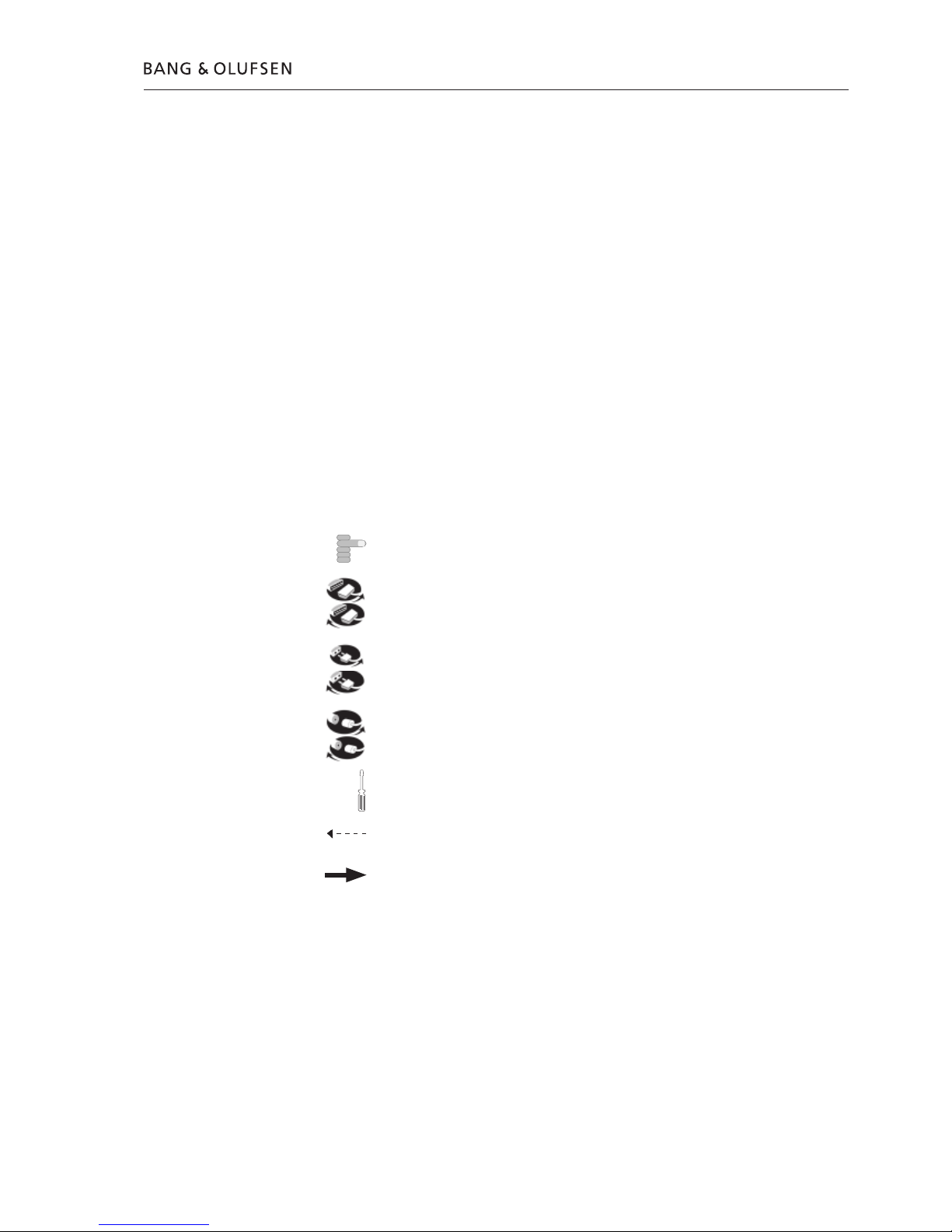
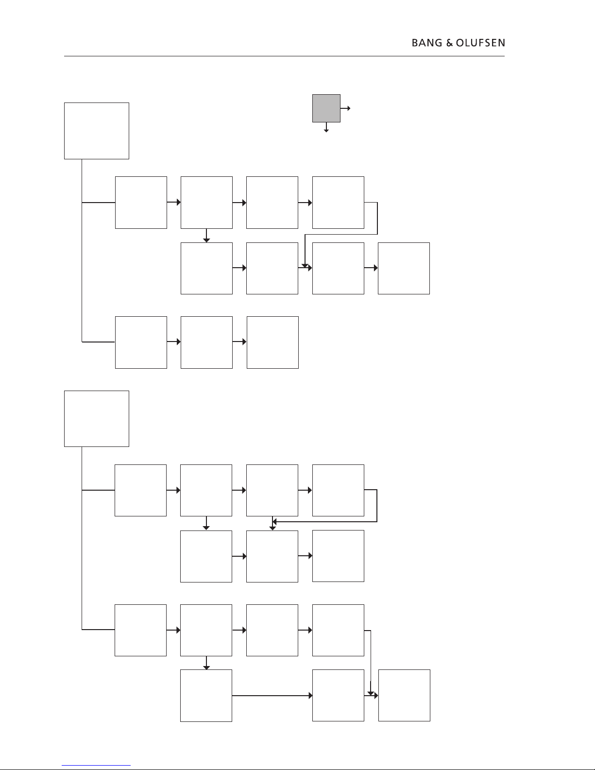
Using theft protection
- Deactivating. BeoSound 1 must be in stand by. Press ltwice then STOP. Use l
and nto reveal digits then STORE.
After last digit press STORE, DELETE and STORE.
- Activating. BeoSound 1 must be in stand by. Press ltwice then STOP. Use land
nto reveal digits then STORE. After last digit press STORE twice.
Confirm the pin-code by re-entering it.
- Entering pin-code, only if demanded. Use land nto reveal digits then STORE.
After last digit press STORE, and BeoSound 1 switches on to the last used source.
Theft protection, English

2.9
#5 Adjustment after repair of BeoSound 1
Adjustment after replacement of PCB1, Main PCB
BeoSound 1 must be reassembled before this adjustment can be carried out.
- Enter TM44. Set speaker value for each speaker. Use the values from the old PCB1
(Main PCB) if such are available.
Otherwise set all speakers to 0.
See #3 Test mode for further information.
- Press RADIO due to the following set up of tuner in BeoSound 1. TM is still activated.
Enter TM07. Use this to set up the tuner in BeoSound 1. It is very important to
enter No 1 and Nos 5 to 9 as they are not default set to 000.
No 0 00X X is variant of type.
Look underneath BeoSound 1 for Type No. See ➢7.
2581=1; 2582=2; 2583=3; 2584=4; 2585=5; 2586=7; 2587=8; 2590=3
No 1 000
No 2 175 FM start. Type 2584=152
No 3 216 FM stop. Type 2584=180
No 4 0XX XX is variant. Type 2583+2590=75, others=50
No 5 000
N0 6 000
No 7 000
No 8 000
No 9 000
- Turn off BeoSound 1. Remember to follow the guidelines in #6 Test after repair of
BeoSound 1.
Adjustment after replacement of PCB2, SMPS
- If mains voltage from 100V-120V AC ensure that jumper J2 on PCB2 (see ➢6) is
mounted.
- If mains voltage from 220V-240V AC ensure that jumper J2 on PCB2 (see ➢6) is
removed.
Adjustment after replacement of speaker units
Only a simple adjustment is necessary if a speaker unit has been replaced.
- Read-out the value on back of the new speaker unit (➢8.1). Compare with values
in the table and find the speaker value (➢8.2).
- Enter TM44. Set the speaker value for the speaker in question.
See #3 Test mode for further information.
Adjustment after repair of BeoSound 1, English

2.10
#6 Test after repair of BeoSound 1
For information on the general use of BeoSound 1 please refer to the BeoSound 1
Guide.
Reassemble BeoSound 1
- Reassemble BeoSound 1 if not done already. See 11.1 Dissambly/Assembly of
BeoSound 1 if necessary.
Perform an AC leakage test
Check the antenna terminals and other exposed metal parts for AC leakage.
- Remove the line cable from the AC source (the wall outlet).
- Place a jumper across the two AC plug prongs.
- Use a multi-meter, set for measurements in the Ohm-area.
- Place one lead from the multi-meter on the AC plug and place the other lead on
each of the exposed metal parts, that is antenna connection, aerial and front
cover.
- The resistance during these measurements must be of 1 Mega Ohm or more. If
resistance is below 1 Mega Ohm, this indicates an abnormal situation and
corrective actions must be taken.
Please note: Avoid any skin contact either with the AC plug nor the metal parts
while performing the test, as it may influence the measurement.
Connect mains voltage to BeoSound 1
- Reconnect mains voltage and turn on BeoSound 1. See #4 Theft protection if
necessary.
Read-out and clear error codes
- Enter TM27 and read-out the errors for service use. Clear errors when done.
See #3 Test mode if necessary.
Check keyboard functions
- Check that all keyboard buttons are OK.
Check Radio functions
- Tune in and store at least one radio station. Check other radio functions as well.
Check CD functions
- Insert a CD in the CD-loader. The test-CD SBC 444A can be used. Ensure that
tracks 10, 17 and 19 on the CD are being played correctly.
Check speakers
- Ensure that all speakers are playing correctly and without dissonance.
Check surfaces and clean these if necessary
- Use a dry, soft cloth. If necessary remove persistent dirt with a lint-free, firmly
wrung cloth, dipped in a solution of water containing only a few drops of mild
detergent. The front may also be cleaned with a soft brush mounted on a vacuum
cleaner set to the lowest level.
Test after repair of BeoSound 1, English

3.1
Inhalt, Deutsch
#1 Servicearbeiten am BeoSound 1
#2 Fehlersuchdiagramm
#3 Testmodus
#4 Diebstahlsicherung
#5 Einstellungen nach der Reparatur des BeoSound 1
#6 Tests nach der Reparatur des BeoSound 1
10.1 Abbildungen
11.1 Zerlegung/Zusammenbau des BeoSound 1
12.1 Austausch der PCB1, (Haupt-PCB)
13.1 Austausch der PCB2, (SMPS) und PCB3, (Display & IR-Empfänger)
14.1 Austausch der linken/rechten Tastatur
15.1 Austausch der PCB4, (Aktive FM-Antenne)
16.1 Austausch des Antennen-Laders und der Lautsprechereinheiten
17.1 Austausch des CD-Laders und der PCB90 (CD-Mechanismus)
18.1 Reparaturkoffer
19.1 Modulübersicht
Symbolübersicht:
Mit Finger in Pfeilrichtung drücken
Internen Stecker abziehen
Internen Stecker anschließen
Netzstecker abziehen
Netzstecker anschließen
Antennen- oder anderen externen Stecker abziehen
Antennen- oder anderen externen Stecker anschließen
Schraube lösen/ausbauen bzw. anziehen/einbauen
Gestrichelter Pfeil. PCB, Chassis o.ä. in Pfeilrichtung schieben/ziehen
Durchgehender Pfeil. Für weitere Informationen siehe Seite/Kapitel, z.B.
14.1 PCB4, falls eingebaut:
Siehe 14.1 PCB4 und PCB aus- bzw. einbauen.

3.2 Einleitung, Deutsch
STATIC ELECTRICITY
MAY DESTROY THE
PRODUCT
Achtung
Statische Elektrizität kann das Produkt beschädigen!
Für jeden Modulaustausch muss immer ein Antistatik-Servicekit benutzt werden.
ESD-Matte zum Ablegen neuer wie gebrauchter Module benutzen.
#1 Servicearbeiten am BeoSound 1
Benutzung der Vor-Ort-Serviceanleitung
Diese Vor-Ort-Serviceanleitung erläutert die Reparatur und leitet Sie bei den
Reparaturmaßnahmen am defekten BeoSound 1 an.
- Befolgen Sie die Anleitung, um defekte Module zu finden. Benutzen Sie beim
Austausch der Module die Austauschanleitungen im hinteren Teil der Vor-Ort-
Serviceanleitung. Befolgen Sie nach dem Austausch die Einstellungsanweisungen
und Checkliste, um sicherzustellen, dass der Fehler beseitigt ist und alle BeoSound 1
Funktionen einwandfrei sind.
Alle Abbildungen befinden sich im hinteren Teil der Anleitung. Auf eine Abbildung
wird folgendermaßen verwiesen: (siehe ➢X) oder ➢X. Dies bezieht sich auf ➢X
in 10.1 Abbildungen.
WICHTIGER HINWEIS:
Lesen Sie vor der Fehlersuche bitte Abschnitt #4 Diebstahlsicherung.
Reparatur des BeoSound 1
Die Reparatur des BeoSound 1 erfolgt durch den Austausch defekter Module. Dies
kann entweder die Haupt-PCB, das Schaltnetzteil (SMPS) oder eine der anderen
PCBs sein.
Eine vollständige Modulübersicht befindet sich im hinteren Teil der Anleitung.
- Lassen Sie den Kunden vor Beginn der Fehlersuche möglichst den Fehler erklären
und vorführen. Prüfen Sie anschließend, ob:
Das BeoSound 1 auf die richtige Option eingestellt ist. 1 (IR) oder 0 (keine IR).
Die Netzspannung angeschlossen und eingeschaltet ist und die rote Standby-LED
leuchtet.
Eine externe Antenne (falls verwendet) richtig angeschlossen ist.
Die Compact Disc (CD) richtig eingelegt ist und keine stärkeren Kratzer hat.
Benutzen Sie ggf. die Test-CD SBC 444A. Prüfen Sie, ob die Titel 10, 17 und 19
auf der CD korrekt abgespielt werden.
Benutzung des Testmodus (TM) und/oder Fehlersuchdiagramms zur Reparatur
WICHTIGER HINWEIS: Das BeoSound 1 befindet sich im Sicherheitsmodus, wenn
die Standby-LED blinkt und keine Signalquelle gewählt werden kann: Trennen Sie
die Netzspannung und warten Sie 10 s bis zum erneuten Anschluss. Wenn dann
immer noch der Sicherheitsmodus aktiviert ist, beachten Sie bitte, dass das Gerät
durch Aktivierung des TM beschädigt werden kann.
- Wenn möglich, schalten Sie das BeoSound 1 ein und aktivieren Sie den TM.
Aktivieren Sie TM43 und lesen Sie die Werte aus.
Für weitere Informationen siehe Abschnitt #3 Testmodus.

3.3
Einleitung, Deutsch
- Zu Beginn der Fehlersuche siehe bitte Abschnitt #2 Fehlersuchdiagramm.
Der Fehler sollte sich einer der vier Hauptgruppen zuordnen lassen:
Systemfunktion
Tonwiedergabe
Radio
CD
Zerlegen Sie das Gerät, um Zugriff auf die PCBs im BeoSound 1 zu erhalten.
- Wenn möglich, geben Sie TM27 ein und prüfen Sie Fehler 0. Wenn das
Fehlersuchdiagramm und TM27 das gleiche Modul anzeigen, so ist dieses
auszutauschen.
Für weitere Informationen siehe Abschnitt #3 Testmodus.
Andernfalls kann es sinnvoll sein, das Fehlersuchdiagramm erneut durchzugehen,
um sicherzustellen, dass die Fehlerdiagnose richtig ist.
- Nehmen Sie den Modulaustausch vor und prüfen Sie, ob der Fehler beseitigt ist.
Andernfalls sollte das Fehlersuchdiagramm einen weiteren Hinweis auf ein
auszutauschendes Modul geben.
Bei der Benutzung des Fehlersuchdiagramms kann es notwendig sein, Messungen
im Gerät vorzunehmen.
Für eine Spannungsangabe im Fehlersuchdiagramm ist eine Toleranz von ±10-20%
zulässig. Zu Messpunkten siehe ➢X in 10.1 Abbildungen.
- Nach der Fehlerbeseitigung müssen die Maßnahmen in den folgenden
Abschnitten befolgt werden:
#4 Diebstahlsicherung,
#5 Einstellungen nach der Reparatur des BeoSound 1 und
#6 Tests nach der Reparatur des BeoSound 1.

3.4
Standby-
Beleuchtung
1P5Pin10 gegen
Pin3 messen.
5V DC?
➢2
1P5 abziehen und
2P1Pin4 gegen
Pin12 messen.
5V DC?
➢2
PCB2
austauschen
OK?
3P1Pin15 und
3P1Pin18 gegen
Pin1 messen.
15V DC und
2V DC?
➢4
1P600Pin4 und
1P600Pin1 gegen
Pin18 messen.
5V DC und
2V DC?
➢1
PCB1
austauschen
OK?
BS1 zur Reparatur
in die Werkstatt
bringen
PCB3
austauschen
OK?
18-poliges Kabel
von 1P600 zu
3P1 austauschen
OK?
Systemfunktion
IR
Versuch mit
neuer Beo4
OK?
PCB3
austauschen
OK?
PCB1
austauschen
OK?
BS1 zur Reparatur
in die Werkstatt
bringen
Batterien oder
Beo4
austauschen
Tastatur
Fehlfunktion der
linken und
rechten Tastatur?
Linke bzw. rechte
Tastatur
austauschen
OK?
PCB3
austauschen
OK?
PCB1
austauschen
OK?
BS1 zur Reparatur
in die Werkstatt
bringen
Display
PCB1
austauschen
OK?
PCB3
austauschen
OK?
BS1 zur Reparatur
in die Werkstatt
bringen
Nein
Ja
#2 Fehlersuchdiagramm
Fehlersuchdiagramm, Deutsch
Lesen Sie vor der Fehlersuche bitte Abschnitt #4 Diebstahlsicherung

3.5
Antenne auf/ab
1P35Pin2 gegen
Pin1 messen.
5V DC bei
Antenne auf/ab?
➢2
PCB1
austauschen
OK?
BS1 zur Reparatur
in die Werkstatt
bringen
4P154Pin2 gegen
Pin1 messen.
5V DC bei
Antenne auf/ab?
➢5
PCB4
austauschen
OK?
BS1 zur Reparatur
in die Werkstatt
bringen
Antennen-Lader
austauschen
Tonwiedergabe
Alle Lautsprecher
stumm
PCB1
austauschen
OK?
PCB2
austauschen
OK?
BS1 zur Reparatur
in die Werkstatt
bringen
Ein Lautsprecher
stumm
1P500 abziehen
und betreffenden
Lautsprecher
durchmessen.
3-10 Ohm?
➢3
Lautsprecher
austauschen
OK?
PCB1
austauschen
OK?
PCB1
austauschen
OK?
Lautsprecher
austauschen
OK?
BS1 zur Reparatur
in die Werkstatt
bringen
Nein
Ja
Fehlersuchdiagramm, Deutsch

3.6
Radio
Tonstörungen
1P35Pin5 gegen
Pin6 messen.
8V DC?
➢2
PCB1
austauschen
OK?
PCB4
austauschen
OK?
PCB4
austauschen
OK?
PCB1
austauschen
OK?
Antennen-Lader
austauschen
OK?
Andere
Radiofehler
PCB1
austauschen
OK?
BS1 zur Reparatur
in die Werkstatt
bringen
BS1 zur Reparatur
in die Werkstatt
bringen
CD
CD wird nicht
geladen
1P700Pin1 gegen
Pin2 messen.
5V DC beim
Laden?
➢3
1P5Pin12 gegen
Pin10 messen.
16V DC?
➢2
PCB2
austauschen
OK?
CD-Lader
austauschen
OK?
PCB1
austauschen
OK?
BS1 zur Reparatur
in die Werkstatt
bringen
Keine CD-
Wiedergabe
1P2Pin2 und
1P2Pin4 gegen
Pin1 messen.
9V DC und 5V DC
bei CD?
➢1
PCB1
austauschen
OK?
PCB90
austauschen
OK?
PCB90
austauschen
OK?
PCB1
austauschen
OK?
BS1 zur Reparatur
in die Werkstatt
bringen
Nein
Ja
Fehlersuchdiagramm, Deutsch

3.7
Testmodus, Deutsch
#3 Testmodus
Das BeoSound 1 hat einen eingebauten Testmodus (TM).
Benutzen Sie diesen möglichst, um verschiedene Werte auszulesen, die für die
Einstellung des BeoSound 1 nach der Reparatur benötigt werden.
Dieses sind TM27, TM43. Für weitere Informationen siehe Übersicht über Testmodi
im BeoSound 1.
- Sehen Sie sich diese Übersicht möglichst vor dem Zerlegen des Geräts und dem
Austausch von Modulen an.
Benutzung des Testmodus
- Geben Sie den TM entweder über die eingebaute Tastatur oder die Beo4 ein.
Tastatur: DELETE DELETE STOP STOP STORE.
Beo4: LIST (bis SHIFT) + 9 0 2 5 8.
- Geben Sie die gewünschte TM-Nummer ein.
Drücken Sie zum Verlassen ohne Änderungen STOP.
- Beenden Sie den TM mit STANDBY auf der Beo4 oder Tastatur.
Benutzung der Beo4 bzw. eingebauten Tastatur und Auslesen der Anzeige
- Im TM können sowohl die Beo4 als auch die eingebaute Tastatur benutzt werden.
GO auf Beo4 = STORE auf Tastatur.
Um die Tastatur für die numerische Eingabe im TM zu benutzen, drücken Sie
AERIAL, ohne die Taste zu halten, und dann von DELETE zu RADIO>. DELETE ist
0 und RADIO> ist 9. Die weiteren Nummern liegen dazwischen.
Für die nächste Nummer einfach AERIAL, dann DELETE...RADIO> drücken.
- Beachten Sie beim Auslesen der Anzeige im TM, dass auch HEX-Angaben (A...F)
benutzt werden.
Übersicht über Testmodi im BeoSound 1
TM 23 Softwareversion anzeigen
TM23. APP=Anwendung, OS=Betriebssystem, ra=Radio, Cd=Compact Disc.
GO zur nächsten Anzeige drücken.
TM27 Fehler anzeigen
TM27. 16 letzte Fehler. lbzw. nzur Anzeige des vorherigen bzw. nächsten
Fehlers drücken.
4xGO drücken, um alle Fehler zu löschen. STOP zum Verlassen ohne Löschen
drücken.
Displayanzeige Fehler in
0A00 - 0A80 PCB1 (Haupt-PCB)
0B00 - 0B80 PCB1 (Haupt-PCB)
0C01 - 0C20 PCB1 (Haupt-PCB)
0D00 - 0D08 PCB1 (Haupt-PCB)
0E71 PCB2 (SMPS)
0E72 PCB1 (Haupt-PCB)
0F01 - 0F12 PCB90 (CD-Mechanismus)
TM43 Lautsprecherwert anzeigen
TM43. Nr. 1=linker Hochtöner, 2=linker Mitteltöner, 3=Tieftöner, 4=rechter
Mitteltöner, 5=rechter Hochtöner.
GO oder STOP zum Verlassen drücken, für alle Lautsprecher wiederholen.
TM44 Lautsprecherwert einstellen
TM44. Nr. X, wie in TM43.
GO + Wert=positiver dB-Wert. STOP + Wert=negativer dB-Wert.
Für alle Lautsprecher wiederholen.

3.8 Diebstahlsicherung, Deutsch
#4 Diebstahlsicherung
Wenn das BeoSound 1 beim Einschalten zur Eingabe eines Pin-Codes auffordert,
bitten Sie den Kunden, falls möglich, diesen einzugeben.
- Wenn ein Reparaturkoffer für den Service benutzt wird, beachten Sie bitte, dass
ausgetauschte Module immer zur Reparatur an Bang & Olufsen zurückgeschickt
werden müssen, da sie aufgrund der Diebstahlsicherung nicht in anderen Geräten
verwendet werden können.
Für andere Reparaturmethoden, wie z.B. Modulaustausch in einem Servicecenter
oder einer Werkstatt, siehe bitte die Servicecenter-Anleitung für weitere
Informationen.
Wenn die Diebstahlsicherung bei der Reparatur des BeoSound 1 aktiviert ist
Wenn die Diebstahlsicherung aktiviert ist, benutzen Sie den Service-Code, um das
BeoSound 1 nach der Reparatur zu prüfen.
- Bei eingeschaltetem BeoSound 1 l3 Sekunden lang drücken. Es erscheint ein
Mastercode-Menü, in dem der Service-Code 11111 eingegeben werden muss.
Wenn das BeoSound 1 für 12 Stunden mit eingeschalteter Netzspannung gelassen
oder der richtige Pin-Code für die Diebstahlsicherung eingegeben wird, werden
die ausgetauschten Module für dieses BeoSound 1 registriert.
Wenn der Austausch von PCB1 (Haupt-PCB) und von PCB3 (Display & IR-Empfänger) erforderlich ist
Wenn ein Austausch aller Module erforderlich ist, z.B. aufgrund von Blitzschlag, ist
es sehr wichtig, dass der Modulaustausch in der richtigen Reihenfolge geschieht,
da das BeoSound 1 für Diebstahlsicherung vorbereitet ist.
- Sicherstellen, dass PCB2 (SMPS) korrekt funktioniert, ggf. austauschen.
- Entweder PCB1 (Haupt-PCB) oder PCB3 (Display & IR-Empfänger) muss ausgetauscht
werden, und das BeoSound 1 muss eingeschaltet sowie die Diebstahlsicherung
aktiviert werden. Benutzen Sie den richtigen Diebstahlsicherungs-Pin-Code.
- Tauschen Sie dann die andere dieser PCBs aus. Es wird dringend empfohlen, zuerst
PCB1 und dann PCB3 auszutauschen.
- Denken Sie daran, die Diebstahlsicherung zu deaktivieren, wenn diese vom Kunden
nicht benutzt wird.
Wenn das obige Verfahren nicht beachtet wird, besteht ein großes Risiko, dass das
Gerät nicht funktionieren wird und ein neuer Modulsatz bei Bang & Olufsen DK
bestellt werden muss.
Wenn dies erforderlich wird, bauen Sie das Gerät wieder zusammen und nehmen
Sie es in das Servicecenter oder die Werkstatt mit.
Weitere Informationen finden Sie in der Reparaturanleitung für das Servicecenter.
Benutzung der Diebstahlsicherung
- Deaktivierung. Das BeoSound 1 muss im Standby-Betrieb laufen. Zweimal lund
dann STOP drücken. lund nzur Ziffernanzeige und dann STORE drücken.
Nach der letzten Ziffer STORE, DELETE und STORE drücken.
- Aktivierung. Das BeoSound 1 muss im Standby-Betrieb laufen. Zweimal lund
dann STOP drücken. lund nzur Ziffernanzeige und dann STORE drücken. Nach
der letzten Ziffer zweimal STORE drücken.
Pin-Code durch erneute Eingabe bestätigen.
- Eingabe des Pin-Codes, nur nach Aufforderung. lund nzur Ziffernanzeige und
dann STORE drücken. Nach der letzten Ziffer STORE drücken. Das BeoSound 1
schaltet nun mit der zuletzt benutzten Signalquelle ein.
This manual suits for next models
7
Table of contents
Languages:
Other Bang & Olufsen Portable Speakers manuals

Bang & Olufsen
Bang & Olufsen BEOPLAY A2 ACTIVE User manual

Bang & Olufsen
Bang & Olufsen Beolit 17 User manual

Bang & Olufsen
Bang & Olufsen Beosound A5 User manual

Bang & Olufsen
Bang & Olufsen BeoPlay A6 User manual

Bang & Olufsen
Bang & Olufsen BeoSound 1 User manual

Bang & Olufsen
Bang & Olufsen Beoplay P6 User manual

Bang & Olufsen
Bang & Olufsen Beosound Emerge User manual

Bang & Olufsen
Bang & Olufsen Beoplay M3 User manual

Bang & Olufsen
Bang & Olufsen A8 User manual