The Owner’s Responsibility
WARNING: This bicycle is made to be ridden by one rider at a time for general
transportation and recreational use. It is not made to withstand the abuse of stunting and jumping.
If the bicycle was purchased unassembled, it is the owner’s responsibility to follow all assembly and
adjustment instructions exactly as written in this manual, and any “Special instructions” supplied
and to maked sure all fasteners and components are securely tightened.
NOTE: Periodically check that all fasteners and components are securely tightened.
If the bicycle was purchased assembled, it is the owner’s responsibility, before riding the bicycle for
thersttime,tomakesurethebicyclehasbeenassembledandadjustedexactlyaswritteninthis
manual, and any “Special instructions” supplied and to make sure all fasteners and components are
securely tightened.
NOTE:
If product is assembled, please proceed to sections:
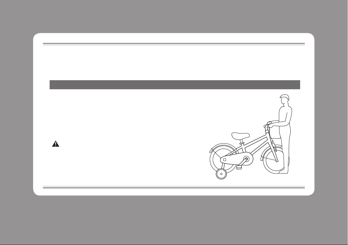
•Testing Stem, Handlebar
•Seat Clamp tightness.
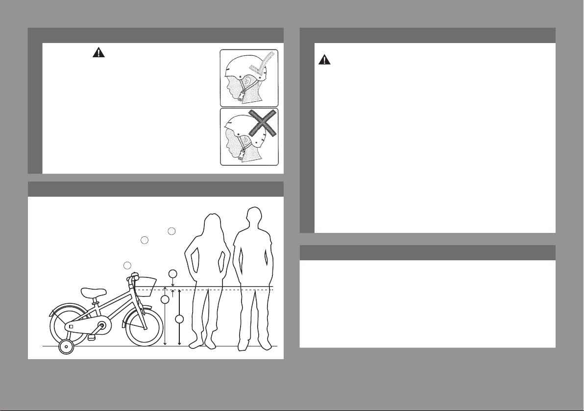
General Warning
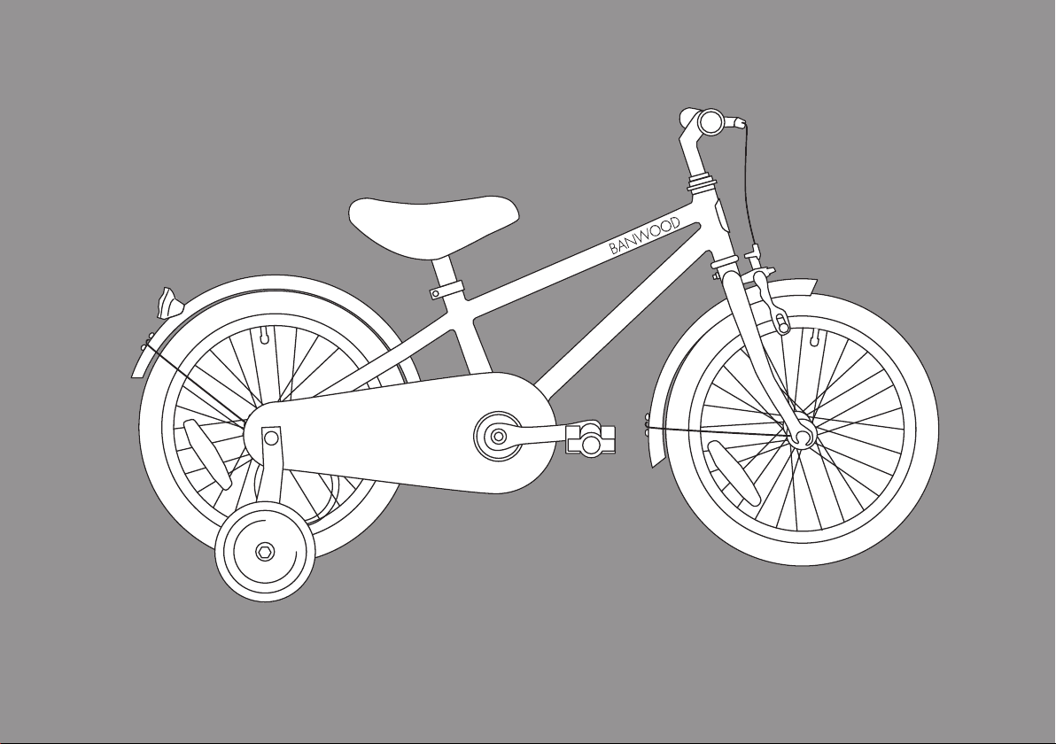
Your Bike
WARNING: Not intented for use on public roads.
•Always wear a bicycle helmet that meets CPSC safety standars, as well as local safety
standards.
•Always wear shoes.
•Bikes 12in (30cm) and under not intended for use on public roads.
•Avoid riding at night, dusk, dawn and any other time of poor visibility.
•Reectors:
•Foryourownsafety,donotridethebicycleifthereectorsareincorrectlyinstalled,
damaged, or missing.
• Doornotallowthevisibilityofthereectorstobeblockedbyclothingorotherarticles.
Dirtyreectorsdonotworkwell.Cleanthereectors,asnecessary,withsoapandadamp
cloth.
• Use extra caution in wet weather:
•Ride slowly on damp surfaces because the tires will slide more easily.
•Allow increased braking distance in wet weather.
• Avoid these hazards to prevent loss of control or damage to your wheels:
•Be aware of drain grates, soft road edges, gravel or sand, pot holes or ruts, wet leaves,
or uneven paving.
•Cross railroad tracks at a right angle to prevent the loss of control.
•Avoid unsafe actions while riding.
•Do not carry any passengers.
•Do not carry any items or attach anything to your bicycle that could hinder your vision,
hearing, or control.
•Do not ride with both hands off the handlebar.
Maximum rider/bike weight for this product is as follows
Bike
Size
Rider Rider + Bike Rider + Bike+Basket
kg lbs kg lbs kg lbs
12 27 60 35.3 78 35.45 78
14 27 60 35.7 79 35.85 79
16 27 60 36.6 81 36.76 81
18 34 75 44.5 98 44.66 99
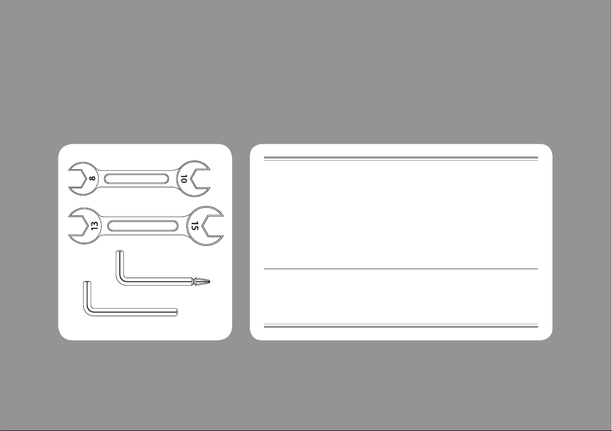
Introduction to Assembly
Assembly
This Owner’s Manual is made for several different bicycles:
•Some illustrations may vary slightly from the actual product.
•Follow instructions completely.
•If the bicycle has any parts that are not described in this manual, look for separate “Spe-
cial Instructions” that are supplied with the bicycle.
•Modelsmayhavedifferentaccessoryitemssuchasbags,baskets,reectors,cupholders,
racks, etc.
•All features, componets and accessories are not included on all models.
•Usetheindexpagetolocatespecicsectionsofthismanual.
•Please read through this entire manual before beginning assembly or maintenance.
•Ifyouarenotcondentwithassemblingthisunit,refertoalocalbikeshop.
WARNING: Keep small parts away from children during assembly.
Do not dispose of the carton and packaging until you complete the assembly of the bicycle.
This can prevent accidentally discarding parts of the bicycle.
NOTE: All of the directions (right, left, front, rear, etc.) in this manual are as seen by the rider
while seated on the bicycle.