Barco MFGD 1318 User manual

User manual MFGD 1318 3
CONTENTS
Safety instructions .............................................................................................. 5
1. Overview ......................................................................................................... 6
1.1. Intro uction.............................................................................................. 6
1.2. Package contents .................................................................................... 7
1.3. Controls an connectors ......................................................................... 8
Front........................................................................................................... 8
Si e ............................................................................................................ 8
Rear ........................................................................................................... 9
2. Installation ..................................................................................................... 10
2.1. Precautions ........................................................................................... 10
2.2. Before installing the isplay .................................................................. 10
2.3. Portrait or lan scape position................................................................ 11
2.4. Connecting the signals .......................................................................... 11
2.5. Routing the signal cables ...................................................................... 13
2.6. Using the USB hub ................................................................................ 14
2.7. Tilt an swivel positioning ...................................................................... 14
2.8. Starting up ............................................................................................. 14
3. Operation ...................................................................................................... 15
3.1. Switching to stan -by position ............................................................... 15
3.2. Controlling the isplay ........................................................................... 15
About the on-screen menus .................................................................... 15
Navigating through the menus ................................................................. 15
Saving changes ....................................................................................... 16
3.3. Using the Autoset* functions ................................................................. 17
When o you nee to use the Autoset functions? ................................... 17
Require test pattern ............................................................................... 17
To enter the Autoset menu: ...................................................................... 17
The Autoset menu contains the following items: ..................................... 18
3.4. Controlling Vi eo Contrast* an Vi eo Brightness* .............................. 18
To enter the menu: ................................................................................... 18
To change Vi eo Contrast or Vi eo Brightness manually: ...................... 19
To select the calibrate position: ............................................................. 19
A itional information .............................................................................. 19
3.5. Setting the Luminance value ................................................................. 19
3.6. Making a justments .............................................................................. 20
How to make the a justments? ............................................................... 20
Geometry a justments ............................................................................. 21
Phase a justments* ................................................................................. 22

3.7. Selecting inputs ..................................................................................... 22
To enter the Inputs menu: ........................................................................ 22
You can select the following input selection settings: .............................. 23
3.8. Settings ................................................................................................. 23
To enter the Settings menu: ..................................................................... 23
The Settings menu contains the following items: .................................... 24
3.9. Preset .................................................................................................... 24
To enter the Preset menu: ....................................................................... 24
The Preset menu contains the following items: ....................................... 25
3.10 Getting information ............................................................................... 25
To enter the Information menu: ................................................................ 25
The General Information menu contains the following items: ................. 26
The Current Input Format information menu contains the following items:26
4. A vance functions ....................................................................................... 27
4.1. About this chapter ................................................................................. 27
About the A vance functions ................................................................. 27
To log in as a vance user: ..................................................................... 27
4.2. A vance functions in the A justments menu ..................................... 28
Geometry ................................................................................................. 28
Ambient Light Compensation .................................................................. 28
Low Pass Filter* ....................................................................................... 29
4.3. A vance functions in the Settings menu ............................................. 29
Display function ....................................................................................... 29
Input Mo e ............................................................................................... 29
OSD position ............................................................................................ 31
4.4. A vance functions in the Preset menu ................................................ 31
Clear user presets ................................................................................... 31
4.5 A vance functions in the Information menu ......................................... 31
Service ..................................................................................................... 31
Firmware .................................................................................................. 32
Runtimes .................................................................................................. 32
5. Maintenance ................................................................................................. 33
Panel ........................................................................................................ 33
Cabinet..................................................................................................... 33
Removing ust from the rear of the glass panel ...................................... 33
6. Troubleshooting ............................................................................................ 34
Win ows oes not show the esire isplay settings .................................. 34
Pixel Faults ................................................................................................... 34
7. Technical specifications ................................................................................ 35

User manual MFGD 1318 5
Read the safety and operating instructions
before operating the apparatus.
Retain safety and operating instructions for
future reference.
Adhere to all warnings on the apparatus and
in the operating instructions manual.
Follow all instructions for operation and use.
This apparatus conforms to: CE, IEC 60950,
UL 60950, CAN/CSA C22.2 No. 950-95 (cUL)
Usage in Hazardous locations
Class I equipment
Equipment not suitable for use in the presence
of a flammable anesthetic mixture with air or
with oxygen or nitrous oxide.
FCC notice
his equipment has been tested and found to
comply with the limits of a class A digital device,
pursuant to Part 15 of the FCC rules. hese
limits are designed to provide reasonable
protection against harmful interference when
the equipment is operated in a commercial
environment. his equipment generates, uses
and can radiate radio frequency energy and, if
not installed and used in accordance with the
instruction manual, may cause harmful
interference to radio communications.
Operation of this equipment in a residential
area is likely to cause harmful interference in
which case the user will be required to correct
the interference at his own expense.
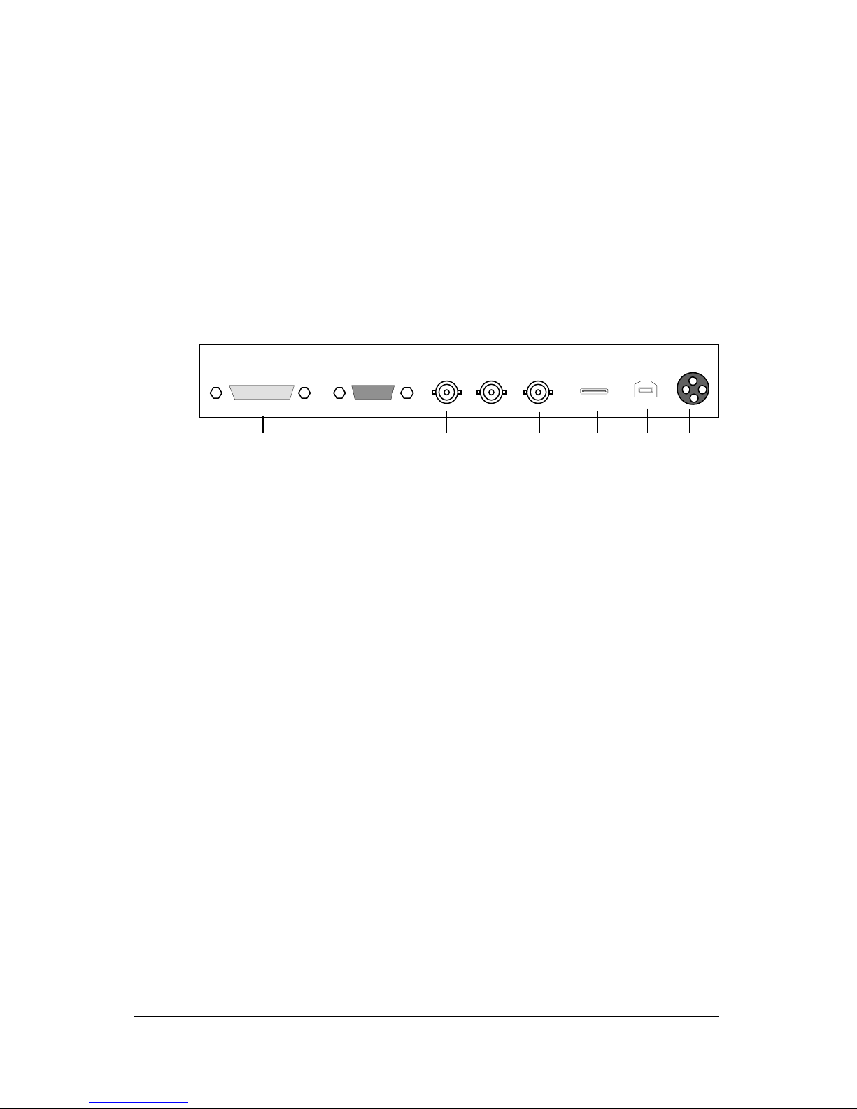
Power connection
Power requirements: he apparatus must
be powered using the 12 VDC power supply
that is supplied with the apparatus.
he 12 VDC power supply must be powered
by the AC mains voltage.
Power cord with CEE 7 plug ( ): he colors
of the mains lead are colored in accordance
with the following code: Green-and-yellow:
Earth (safety earth), Blue: Neutral, Brown:
Line
Power cord with ANSI 73.11 plug ( ): he
wires of the power cord are colored in
accordance with the following code: Green/
yellow: ground, White: neutral, Black: line
(live)
Power requirements: connect the apparatus
to an AC voltage as indicated at its back. Using
a lower voltage, the apparatus will not be able
to operate. Using a higher voltage may
damage the apparatus. If you are not sure of
the type of power supplied, consult the power
company.
Do not overload wall outlets and extension
cords as this may result in fire or electric
shock.
Mains lead protection (U.S.: Power cord):
Supply cords should be routed so that they
are not likely to be walked upon or pinched
by items placed upon or against them, paying
particular attention to cords at plugs and
receptacles.
Water and moisture
Never expose the apparatus to rain or
moisture.
Never use the apparatus near water - e.g. near
a bathtub, washbasin, swimming pool, kitchen
sink, laundry tub or in a wet basement.
Ventilation
Do not cover or block the ventilation openings
in the cover of the set. When installing the
apparatus in a cupboard or another closed
location, heed the necessary space between
the set and the sides of the cupboard.
Installation
Place the apparatus on a flat, solid and stable
surface that can bear the weight of at least 3
monitors. If you use an unstable cart or stand,
the set may fall, causing serious injury to a
child or adult, and serious damage to the
equipment.
More warnings in the Installation chapter.
SAFETY INSTRUCTIONS

User manual MFGD 1318 6
1. OVERVIEW
1.1. Introduction
The MFGD 1318, BARCOs 18 1 megapixel grayscale LCD isplay,
guarantees perfect image quality in me ical imaging applications.
The isplay combines a TFT (thin film transistor) liqui crystal isplay
panel structure an a built-in backlight with inverter for a better picture
quality. It is esigne to meet the users nee s for performance,
consistency, an outstan ing image quality through a streamline
evelopment process.
If the Portrait Accelerator option is installe , the isplay can be use
in portrait or lan scape version, simply by turning the panel. The tilt &
swivel foot allows i eal positioning of the panel, in height an viewing
angle.
The panel can be a juste by means of a control wheel on the
isplay.
I-Guard
I-GUARD® is Barcos patent-pen ing, built-in calibration evice,
continuously maintaining image quality. With I-GUARD®, QA checks
no longer nee to isturb normal ra iology activities, as they can be
performe while applications are running.
I-GUARD® allows ra iologists or QA a ministrators to calibrate their
viewing stations or a just the panels curve to DICOM stan ar s
without a ministrator intervention.
Autoset feature
The isplay has an Autoset feature that helps the user to a just
stan ar presets: With one single function, you can automatically
a just the isplay completely.
Autoscan
When you connect a vi eo signal, the isplay checks in the internal
memory if the signal has been a juste before. If so, it selects the
settings an parameters that match the connecte signal.
When you connect a vi eo signal that hasnt been connecte before,
an a just the isplay to the signal, the a justments an signal timing
parameters are store in a programmable preset.

User manual MFGD 1318 7
Best resolution
The optimum an recommen e resolution is 1280 x 1024 or 1024 x
1280 (if the Portrait Accelerator option is installe ).
The recommen e refresh rate is 60 Hz.
Would you have trouble selecting a proper display setting in
Windows please refer to the Troubleshooting section further.
BARCOs BarcoMe 1MP2FH imaging boar is the best choice to
rive the MFGD 1318 isplay.
Power saving (DPMS)
The MFGD 1318 is equippe with a power saving system.
When left i le for a certain time, the computer connecte to the
isplay, will power own the isplay. The power saving system can be
switche on or off using the on-screen menus.
This system requires a computer imaging boar that supports power
saving management.
Ambient Lig t Compensation (ALC)
When enable , the ALC system automatically a apts the isplay light
output, epen ing on the ambient light in the room. The ambient light
is measure by the ALC optical sensor locate at the front of the
isplay.
1.2. Package contents
The package shoul inclu e the following items, please check. If
some of the items are missing, please contact the reseller from whom
you have purchase the unit.
- The MFGD 1318 isplay
- Power supply
- DVI cable
- Analog vi eo cable
- USB cable
- Two velcro strips to bin the cables
- European power cor
- American power cor
- This user manual
If the isplay is part of a Coronis system, the package contains more
items. Please refer to the packing list on the outsi e of the Coronis
box.

User manual MFGD 1318 8
1
2
1.3. Controls and connectors
Front
(1) Ambient Light Compensation (ALC) sensor
(2) Power LED
- The LED is off when the isplay is off. The LED is also off when the
isplay is on but the LED is isable in the on-screen menus.
- The LED is green when the isplay is on (when enable in the on-
screen menus).
- The LED is orange when the isplay is in Stan -by power-saving
mo e.
Side
(3) USB ownstream connector
(4) Control wheel for navigating through the on-screen isplay (OSD)
menus an changing values in the menus
4
3

User manual MFGD 1318 9
Rear
(5) Digital DVI (vi eo an ata) input
(6) D15 (VGA) vi eo connector
(7) Vertical sync input
(8) Composite / Horizontal sync input
(9) Composite vi eo input
(10) USB ownstream connector
(11) USB upstream connector
(12) DC 12V power input
D15DVI VIDEOCS/HSVS
56789101112

User manual MFGD 1318 10
2. INSTALLATION
2.1. Precautions
Keep your original packaging. It is esigne for this isplay an is
the i eal protection uring transport.
Avoi reflections in the flat panel to re uce eye strain.
Place the isplay on a strong an stable table or esk.
Keep the isplay away from heat sources an provi e enough
ventilation in case it is built in a rack or console.
Make sure all equipment is switche off before connecting the
signals.
2.2. Before installing the display
Important:
In the factory, the height-positioning system in the isplay foot is
blocke with a strap to prevent amage uring transportation.
Before installing the isplay, you must remove this strap.
Strap
To remove the strap:
1 Position the isplay with its rear si e facing you.
2 If the foot cover is mounte on the foot, lift up the 2 clips of the foot
cover to release the cover from the foot.
3 Pull the lower si e of the cover towar s you an simultaneously
sli e the cover ownwar .
4 Pull the re strap out of the fixation holes in the foot.
You can better leave the cover off the foot while connecting the signal
cables to the isplay.

User manual MFGD 1318 11
2.3. Portrait or landscape position
You can change the orientation of the panel at any time, but it is more
convenient to select lan scape or portrait orientation before connect-
ing the cables.
To change the panel orientation:
1 Stan at the front si e of the panel an take the panel at both
si es.
2 Very important: Tilt the panel before changing the orientation.
Shoul you change the panel orientation without tilting it first, you
might irreversibly amage the tilt & swivel mechanism.
3 To change from portrait to lan scape, turn the panel
counterclockwise while tilting it slightly.
To change from lan scape to portrait, turn clockwise.
2.4. Connecting the signals
To get access to the connectors, open the cover of the connector
compartment by pulling own the 2 clips of the cover.
The signal cables can be route insi e the isplay foot. Therefore,
remove the foot cover before connecting the signals (see "Before
installing the isplay").
Important:
Do not connect vi eo an sync signals to the BNC an D15 connec-
tors at the same time.
To connect DVI signals:
1 Connect one en of the DVI cable to the DVI input (5) of the
isplay.
2 Connect the other en of the DVI cable to the vi eo output of your
DVI signal source.
3 Route the cable so that it enters the connector compartment at the
place where the cover is bulge .

User manual MFGD 1318 12
To connect analog video & sync signals on BNC:
Connect the vi eo & sync output of the signal source to the vi eo an
sync inputs (9), (8) an (7) of the isplay.
The inputs accept the following signals:
Vi eo with separate horizontal an vertical sync.
- The connection consists of 3 cables.
- Connect the vi eo signal to the connector Vi eo (9).
- Connect the horizontal sync signal to the connector HS/CS (8).
- Connect the vertical sync signal to the connector VS (7).
-Make sure the signal connected to the HS/CS connector
does not contain Composite sync.
Vi eo with external composite sync.
- The connection consists of 2 cables.
- Connect the vi eo signal to the connector Vi eo (9).
- Connect the composite sync signal to the connector HS/CS (8).
-Make sure no signal is connected to the VS connector.
Vi eo with internal composite sync (sync on vi eo).
- The connection consists of 1 cable.
- Connect the vi eo (with sync) signal to the connector Vi eo (9).
Notes:
The vi eo inputs cannot be connecte in loop-through ( aisy-chain).
The require vi eo amplitu e: 700 mV ± 3 B.
The require sync. amplitu e:
- VS input: 700 mV to 4 V
- HS/CS input: 500 mV to 4V
- Vi eo input (sync on vi eo): 150 mV to 600 mV
To connect analog video & sync signals on D15:
1 Connect one en of the VGA cable to the D15 input (6) of the
isplay.
2 Connect the other en of the VGA cable to the vi eo output of your
computer.
3 Route the cable so that it enters the connector compartment at the
place where the cover is bulge .
To connect the power:
1 Connect the output of the 12V DC power supply to the DC input (12)
of the isplay.
2 Connect one en of the proper power cable to the AC input of the
12V DC power supply.

User manual MFGD 1318 13
3 Connect the other en of the power cor to a groun e power
outlet.
4 Route the cable so that it enters the connector compartment at the
place where the cover is bulge .
2.5. Routing the signal cables
After connecting all cables, fix them in the cable tie at the rear of the
connector compartment. Bin the cables together above an un er
the foot, by means of the 2 velcro strips inclu e in the package.
After fixing the cables, put the connector compartment cover back in
place. Pay attention that the signal cables are positione un er the
bulge in the cover.
Next, fix the cables in the plastic clamps on the foot. At last, put the
foot cover back in place.
To put the foot cover in place:
1 Push the upper si e of the cover onto the foot, so that the hooks
on the cover are positione right un er the holes in the foot.
2 Sli e the cover upwar while moving the lower si e of the cover
towar s the foot.
3 Press the cover to the foot so that both clips make a clicking
soun .
Connect to DC
input of the isplay
Connect one en of
power cable
Push the upper side of
the cover onto the foot Signal cables routed under foot cover
and bound by velcro strips
Connector
compartment

User manual MFGD 1318 14
2. . Using the USB hub
To use the isplay in a configuration controlle by Me iCal Pro,
connect the isplay to the PC using the USB connector.
Also, the USB interface insi e the isplay allows you to connect USB
evices, such as a keyboar , mouse or igital camera, to the isplay.
To use t e USB ub:
1 Connect the isplays USB upstream connector (11) to the USB
port of the PC.
2 Connect any USB evice to any of the isplays USB ownstream
connectors (3) or (10).
2.7. Tilt and swivel positioning
A just the position of the panel for best viewing con itions.
The isplay foot allows a justing the horizontal viewing angle, vertical
viewing angle an panel height.
2.8. Starting up
Procee as follows:
1 Switch on the signal source (E.g., PC).
2 If necessary, select a suitable resolution or signal format for the
signal source.

User manual MFGD 1318 15
3. OPERATION
3.1. Switching to stand-by position
When the isplay is on an no on-screen menus are visible, press the
control wheel (4) for a few secon s to switch the isplay in stan -by.
When the isplay is in stan -by, press or turn the control wheel to
switch it back on.
3.2. Controlling the display
The control wheel (4) at the bottom (lan scape orientation) or at the
si e (portrait orientation) allows you to perform controls.
The control wheel is a rotation - click system. It provi es the following
functions:
Short click: Enter menus, confirm selections, an toggle between
ifferent options
Rotate: Browse through menus, increase or ecrease a justment
values
About t e on-screen menus
The content of the on-screen menus epen s on the selecte
vi eo input: Some of the functions are present in the analog
mo es (BNC an DB15) but are not present in DVI mo e.
The functions that are not present in DVI mode are indicated
with an * throughout this manual.
Navigating t roug t e menus
The menu system has a hierarchical structure, with several levels.
To isplay the on-screen menus, turn the wheel (4). The Main
Menu appears. This is the top level of the menu system.
MFGD 1318
MAIN MENU
Autoset*
Video Contrast*
Video Brightness*
Luminan e
Adjustments
Input Sele tion Auto
Settings
Preset
Information
EXIT * Not in DVI mode

User manual MFGD 1318 16
To browse or scroll through the menus on the current level, turn the
wheel clockwise or counterclockwise.
To enter into a menu or move to a lower level of the menu
structure, turn the control wheel to select the esire menu. Next,
click the wheel shortly.
To exit from a menu or move to a higher level of the menu
structure, turn the control wheel to select EXIT. Next, click the
control wheel shortly.
If you o this when you are in the Main Menu, you exit the menu
system.
Some a justments can be ma e by changing an a justment value.
To change an a justment value:
- Turn the control wheel to select the a justment
- Click the wheel shortly. The a justment name appears, as well
as the current a justment value
- Turn the wheel to change the value
- Click the wheel shortly to confirm the change an return to the
menu
Some a justments can be ma e by selecting from a range of
pre efine settings. To change the selection:
- Turn the control wheel to select the a justment
- Click the wheel until the esire setting appears in the menu.
Saving c anges
When you have change something an you wish to exit from the
main menu, the isplay asks if you wish to save the changes.
Save Changes?
Yes
No
1 Turn the control wheel to select Yes (to save the changes) or No (if
you o not wish to save the changes).
2 Click the control wheel to confirm the choice.
Info: The memory of the display contains maximum 200 fixed and 28
programmable presets.
When you connect a video signal, the display checks in the memory for a
matching preset.
f it finds one, it selects the corresponding settings and parameters from the
memory. f it does not find a matching preset, the display uses default settings
to display the image.
When you make adjustments and save the changes, the current preset is
saved as programmable preset. f this happens while all programmable
presets are occupied, the oldest programmable preset is overwritten automati-
cally.

User manual MFGD 1318 17
3.3. Using the Autoset* functions
* Not in DVI mode
The Autoset menu provi es a set of functions to a just the isplay
automatically.
W en do you need to use t e Autoset functions?
It is necessary to perform the Auto Gain an Auto Phase calibrations
in the following cases:
The first time you use the isplay on an analog vi eo
After connecting or selecting another analog vi eo source
It is necessary to perform the Automatic Geometry function in case
you notice the image geometry or positioning is not as esire .
Required test pattern
To obtain goo results with the autoset functions, it is necessary to
have a goo image on which to perform the functions.
For Auto Geometry, the pattern shoul be an image that is fille up to
the e ges, from left to right an top to bottom. The e ges of the image
shoul have an intensity of at least 15% vi eo amplitu e. E.g., a
Win ows esktop pattern woul be a goo image.
For Auto Phase, the pattern shoul contain sharp black-white transi-
tions, like a line pattern or characters.
For Auto Gain, the pattern shoul contain parts that are completely
black (0% vi eo amplitu e) an parts that are full white (100% vi eo
amplitu e).
To enter t e Autoset menu:
1 In the main menu, turn the control wheel to select the Autoset
menu.
MFGD 1318
MAIN MENU
Autoset*
Video Contrast*
Video Brightness*
Luminan e
Adjustments
Input Sele tion Auto
Settings
Preset
Information
EXIT * Not in DVI mode

User manual MFGD 1318 18
2 Click the control wheel. The Autoset menu appears.
AUTOSET
Full Autoset
Automati Geometry
Automati Phase
Automati Gain
EXIT
3 Turn the control wheel to select the function you wish to execute.
4 Execute the function as escribe below.
T e Autoset menu contains t e following items:
Full Autoset ................. Click the control wheel to perform all Autoset
functions (below) one after another.
Automatic Geometry ... Click the control wheel to a just the image
geometry automatically. This function mea-
sures the start an the en of the incoming
vi eo signal. It isplays the complete active
vi eo in the center of the screen an , if the
active vi eo is smaller than the native panel
resolution an no scaling is selecte (see
further), it puts black bor ers aroun the active
vi eo win ow.
Automatic Phase .........Click the control wheel to a just the vi eo
sampling phase an frequency automatically
Automatic Gain ...........Click the control wheel to a just the vi eo
levels (black an white) automatically
3.4. Controlling Video Contrast* and Video
Brightness*
* Not in DVI mode
To enter t e menu:
1 In the main menu, turn the control wheel to select the Vi eo
Contrast or Vi eo Brightness menu.
2 Click the control wheel to enter the Vi eo Contrast or Vi eo
Brightness menu. You can change the current setting manually or
select the calibrate position.

User manual MFGD 1318 19
To c ange Video Contrast or Video Brig tness manually:
1 Turn the control wheel to select the manual Contrast (Brightness)
control.
VIDEO CONTRAST
Contrast CAL position
Man Contrast adj
EXIT
2 Click the control wheel to enter the control.
3 Turn the control wheel to change the Vi eo Contrast or Vi eo
Brightness value.
4 Click the control wheel to confirm the change of the value.
5 Turn the control wheel to select EXIT. Next, click the control wheel
shortly to return to the Main menu.
To select t e calibrated position:
1 Turn the control wheel to select the "Set to Cal position" selection
menu.
VIDEO CONTRAST
Contrast CAL position
Man Contrast adj
EXIT
2 Click the control wheel to switch to the calibrate position.
3 Turn the control wheel to select EXIT. Next, click the control wheel
shortly to return to the Main menu.
Additional information
- If you change Vi eo Contrast or Vi eo Brightness manually, the
change value is save in the memory.
3.5. Setting the Luminance value
With this function, the backlight value is stabilize by the I-Guar
sensor. The value you enter is the target backlight luminance, ex-
presse in C /m².

User manual MFGD 1318 20
Procee as follows:
1 In the main menu, turn the control wheel to select the Luminance
menu.
MFGD 1318
MAIN MENU
Autoset
Video Contrast*
Video Brightness*
Luminan e
Adjustments
Input Sele tion Auto
Settings
Preset
Information
EXIT
2 Click the control wheel. The Luminance menu appears.
3 Turn the control wheel to a just the luminance target value.
4 Click the control wheel to return to the main menu.
3. . Making adjustments
How to make t e adjustments?
1 In the main menu, turn the control wheel to select the A justments
menu.
MFGD 1318
MAIN MENU
Autoset
Video Contrast*
Video Brightness*
Luminan e
Adjustments
Input Sele tion Auto
Settings
Preset
Information
EXIT
2 Click the control wheel. The A justments menu appears.
ADJUSTMENTS
Geometry
Phase*
EXIT
* Not in DVI mode

User manual MFGD 1318 21
3 Turn the control wheel to select the a justment menu you wish to
enter: Geometry or Phase.
4 Click the control wheel to enter the menu.
5 Turn the control wheel to select the a justment you wish to execute.
6 Click the control wheel.
7 Execute the a justment as escribe below.
Geometry adjustments
T e Geometry menu contains t e following items:
Automatic Geometry* .... This is the same function as in the Autoset
menu. Please refer to the escription of the
Autoset functions above. After Automatic
Geometry, the image is centere insi e the
active vi eo win ow. Its size epen s on the
vi eo resolution an the Scaling setting.
Hor Pos* ........................ Turn the control wheel to position the image
horizontally inside the active vi eo win ow
Vert Pos* ....................... Turn the control wheel to position the image
vertically inside the active vi eo win ow
Scaling .......................... Click to select the esire scaling option:
- None: The image is not scale
- Best Fit: The image is scale
proportionally to obtain the best
fit
- Full Screen: The image is scale non-
proportionally to fill the screen
both horizontally an vertically
Orientation** ............ Click to select the esire option:
- Auto: The isplay selects portrait or
lan scape repro uction
automatically, epen ing on the
orientation of the panel.
- Portrait: The image is repro uce in
portrait orientation.
- Lan scape: The image is repro uce in
lan scape orientation.
* Not in DVI mode
** Available only if the Portrait Accelerator option is installed

User manual MFGD 1318 22
P ase adjustments*
* Not in DVI mode
Required test pattern
To obtain goo results, it is necessary to have a goo image on which
to perform the functions.
For the Phase a justments, the pattern shoul contain sharp black-
white transitions, like a line pattern or characters.
T e P ase menu contains t e following items:
Automatic Phase ..... Click the control wheel to a just the vi eo
sampling phase an frequency automatically
Frequency ............... Turn the wheel to a just the vi eo sampling
frequency manually
Man Phase a j ........ Turn the wheel to a just the vi eo sampling
phase manually
We recommen you use the automatic a justment routine only. The
manual controls are inten e for a vance users who wish to fine-
tune the result of the automatic routine.
3.7. Selecting inputs
To enter t e Inputs menu:
1 In the main menu, turn the control wheel to select the Input
Selection menu.
MFGD 1318
MAIN MENU
Autoset
Video Contrast*
Video Brightness*
Luminan e
Adjustments
Input Sele tion Auto
Preset
Settings
Information
EXIT
* Not in DVI mode
Other Barco Monitor manuals

Barco
Barco SF-10V User manual

Barco
Barco MDSC-8255 MNA User manual

Barco
Barco Coronis User manual

Barco
Barco Nio Color 2MP User manual

Barco
Barco X 1.2 User guide

Barco
Barco HDM 5049 PLUS User manual

Barco
Barco MFCD 1218 User manual

Barco
Barco MDNG-5221 User manual

Barco
Barco NX--4 User manual

Barco
Barco MDRC-2124 TS Owner's manual

Barco
Barco SLite User manual

Barco
Barco MDSC-2242 User manual

Barco
Barco TCD-361 User manual

Barco
Barco LDX46 User manual

Barco
Barco Nio systems Instruction Manual

Barco
Barco Eonis MDRC-2224 User manual

Barco
Barco OverView OVL815 Owner's manual

Barco
Barco SP-10 User manual

Barco
Barco ILite User manual

Barco
Barco MDRC-2124 User manual