Barford SR124 Installation and operation manual

1
1
MODEL SR124
MODEL SR124
OPERATOR MANUAL + PARTS LIST

2
MODEL SR124
2
Contents
1 Introduction.............................................................................
2 Warranty..................................................................................
3 EU Declaration........................................................................
4 Safety Recommendations........................................................
5 Know Your Machine...............................................................
6 Power Unit and Controls.........................................................
7 Conveyor in Transit to Working Position...............................
8 Operating the Diesel Powered Conveyor................................
9 Maintenance............................................................................
10 Technical Specification.........................................................
11 Hydraulic Schematic.............................................................
12 Spare parts………………………………………………….
3
4
7
8
12
15
20
21
24
34
35
36

3
3
MODEL SR124
Thank you for purchasing a BARFORD screener.
This manual is as important as your screener and should be read thoroughly before operating your machine.
Safety is always at the forefront at Barford Equipment Ltd. It is recommended that all safety information should be read and
followed.
MANUFACTURER:
Barford Equipment Ltd
72-74 Omagh Road
Dromore
Co.Tyrone
N.Ireland
BT78 2AJ
Tel: + 44 (0) 2882 897401
Serial Number: ______________________
Product / Model: ______________________
1) INTRODUCTION

4
MODEL SR124
4
Barford Screeners have one year warranty on labour and on all non consumable parts e.g. filters and scrapers.
All Barford Screeners are carefully examined and tested before leaving the premises.
Every Barford machine must be registered for warranty. Please complete the Warranty Registration Certificate on the next page.
One copy should be kept by you the customer and a copy returned to Barford Conveyor Systems at the above address. Before
warranty can be honoured a Warranty Certificate must be held on file at BARFORD EQUIPMENT LTD.
NOTE: If servicing or repairing any parts that is non factory supplied will invalidate the warranty. It is the sole
responsibility of the operator to read, understand and comply with all instructions as stated in this manual.
2) WARRANTY

5
5
MODEL SR124
Barford Equipment Ltd
72-74 Omagh Road
Dromore Co.Tyrone
N.Ireland BT78 3AJ
T: + 44 (0) 2882 897401
Registration Certificate
Your Warranty starts from the day that warranty registration has taken place
Date:______________________ Serial Number:_________________________
SAFETY
Has the Manual been read and understood?
Have you carried out a risk assessment for the proposed working area?
Do you have a proper working Radio Remote (optional extra)?
Is the machine set up on a level surface?
Any extra options are in place?
All guards are fitted and secure?
Are you happy with the first test of the machine?
If not, why?
HYDRAULICS AND THE MACHINE
Check oil level and for water in the diesel tank?
Comments________________________________________________
Check oil level in hydraulic tank?
Comments________________________________________________
Are the control valves operating?
Any leaks in the hydraulic system?
Are all persons who will be operating the machine fully trained
and informed of the workings of the machine?
Is the control panel and emergency stops in good working order?
Is the belt tracking?
Checked tension of discharge belt?
Copy to be retained and hard copy to be returned to above address.
Please Note: no warranty registration received means no warranty on machine
YES NO
YES NO
YES NO
YES NO
YES NO
YES NO
YES NO
YES NO
YES NO
YES NO
YES NO
YES NO
YES NO
YES NO
YES NO
2) WARRANTY CONTINUED

6
MODEL SR124
6
Copy to be retained & hard copy to be returned to BARFORD office.
Please note: No warranty registration received, means no warranty on the machine!
Customer Name:
BARFORD Dealer/Distributer:
Customer Contact Name:
Contact:
Customer Contact:
Phone Number:
Customer Full Address:
Application:
Engine Registered:
Instruction Manual Received:
Notes or Comments:
I the undersigned confirm that I have received the Barford product and that the operators fully understand the operations of the
machine. I was present when all checks were marked and I hereby sign below to agreeing to the conditions of the Barford
warranty:
Signatures:
YES NO
YES NO
2) WARRANTY CONTINUED

7
7
MODEL SR124
We the undersigned:
Barford Equipment Ltd
72-74 Omagh Road
Dromore
Co.Tyrone
N.Ireland
BT78 3AJ
Declare under our sole responsibility that the following apparatus:
BARFORD
Model:_________________________
Serial Number:___________________
Is in conformity with the following relevant EC legislation:
Machinery Directive 2006/42/EC
Based on the following harmonised standards: EN12100-2:1998, EN ISO 14121-1:2007, BS EN 982:1996+A1:2008 and
therefore complies with the following essential requirements of the Machinery Safety Directive EHSR1.1, EHSR1.2, EHSR1.3,
EHSR1.4, EHSR1.5, EHSR1.7.
We the undersigned, undertake to transmit, in response to a reasoned request by national authorities, relevant information on the
machinery by the following method of transmission:
Parcel
Name and position of person binding the manufacturer or authorised representative:
Signature:________________________
Name:
Function:
Location: Same as above address
Date of issue:______________________
3) EU DECLARATION OF CONFORMITY

8
MODEL SR124
8
The Barford Screener is designed with Safety in mind.
Barford Equipment Ltd reserve the right not to take responsibility for any injury or damage if the manual is not read and
followed.
Ensure all operators are familiar with the machine, its functions and capabilities. Inadequate knowledge of the machines
operation can lead to death or serious injury. Before commencing any maintenance work ensure that all energy sources i.e.
Diesel Engine or Electric Power pack are locked out using the isolators provided and signs are in place indicating that
maintenance work is being carried out.
Ensure the machine cannot be started while others carry out work on the machine by locking out all energy sources.
All moving parts are covered by guards and shields to prevent accident or injury. If in the event of repair work or servicing to be
carried out, these covers may be removed. Removed guards and shields should be replaced immediately after maintenance work
is finished.
Operating the machine is not permitted with missing guards.
Ensure machine is operated and driven on a level and stable surface.
OPERATING MACHINE SAFELY
•Read the operator’s manual carefully taking note of all the safety information.
•DO NOT attempt to adjust the conveyor belt while they are running.
•If excessive machine vibration occurs, stop the engine and remedy the problem.
CHEMICAL SAFETY
•Always follow instructions on chemical container
•Protective clothing should be worn when using chemicals (gloves and goggles).
•Use the appropriate tools when opening a chemical container.
•Always use a well ventilated area.
DO NOT smoke, eat or drink while handling chemicals. Dispose of all waste in line with local and national regulations.
HIGH PRESSURE FLUIDS
•Check all hoses and lines regularly. Replace when needed.
•Check all connections and tighten when needed.
•Always relieve pressure if fluid escapes before disconnecting hydraulic hose or lines.
•DO NOT use your bare hands or parts of the body to check for leaks.
•Always seek medical help if an accident occurs.
4) SAFETY RECOMENDATIONS

9
9
MODEL SR124
OPERATING PERSONNEL
•Only authorized, competent or trained personnel should operate the Barford conveyor.
•Only authorized, competent or trained personnel should carry out and maintenance work on the Barford screener.
•All instructions should be followed.
PLANT MANAGEMENT IS RESPONSIBLE FOR
•The working area around the machine and the machine itself.
•Any persons in the area of the equipment.
•Any persons operating the equipment.
•Safety of any persons carrying out machine maintenance on site.
•Risk assessment and Health & Safety regulations are adhered to (local and national).
•Ensuring that all doors and guards are closed and installed correctly.
•Ensuring that all maintenance issues, electrical or mechanical, are fixed before machine is operated.
ON SITE ENVIRONMENT
•Risk assessment should be carried out before, during and after operation of the machine.
•Ensure appropriate measures are taken for site personnel training in Health & Safety awareness.
•All hazardous materials must be handled in accordance with the manual instructions.
APPROPRIATE CLOTHING
•All persons operating the machine should wear appropriate clothing e.g. Hard hat, ear protection, dust masks and protective
footwear.
•Any loose clothing should be tucked in and kept away from rotating parts.
WORKING WITH ELECTRICS
•It is recommended that any persons working with the electrical operations on the sceener must work to the standards of
EN50110 or similar.
•Before starting machine ensure that all electrical cables and connectors are in good working order. Also de-energised parts
are checked for presence of power and ground or short circuit them in addition to insulating elements and adjacent live
parts.
•Use recommended current rating original fuses. If the operator suspects that there is a problem, switch off the machine
immediately.
•Before starting the machine the isolator that carries the high voltage must be earth bonded by a qualified electrician.
•Always risk assess the area where the machine will be in operation for overhead cables and other dangerous obstacles. If
contact is made with a live wire, de-energise and alert all persons about approaching and touching the machine
immediately.
•When cleaning the screener DO NOT hose down any electrical enclosures or the electrical motor.
4) SAFETY RECOMMENDATIONS CONTINUED
10
MODEL SR124
10
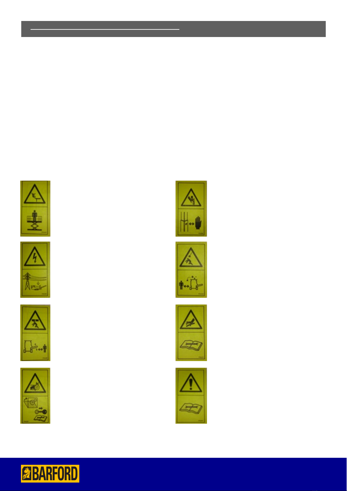
DECALS FOR MACHINE SAFETY
Operators should be familiar with all equipment and be trained in their safe use. Before operation the operator must:
•have read and understood the operators manual and all safety signs in the manual and on the machine have received
specific and adequate training in the operation to be carried out.
•Know the location and function of all controls on the machine.
•Know the location of all Emergency Stops and other safety equipment.
•Be aware of all moving parts of the machine.
Listed below are all the safety signs used throughout this manual and on the machine. Operators must be familiar with these
signs and be aware of their meaning. These signs are used in this manual to warn of some of the potential hazards, which may
exist while operating this machine.
WARNING: Possibility Of Falling From Height.
Use a suitable man lift to access maintenance areas.
WARNING: Electric Shock Hazard.
Beware of overhead cables when setting up or
moving the machine.
WARNING: Possibility Of Crushing By
Overhead Conveyor.
Stay a safe distance from the conveyor while it is
being raised or lowered.
WARNING: Finger Crush Hazard.
Be careful when removing and replacing prop
leg pins.
WARNING: Falling Objects Hazard.
Stay a safe distance from area.
WARNING: High Pressure Fluids Hazard.
Read the instruction manual before proceeding.
WARNING: Entanglement In The Screener
Hazard.
Make sure all guards are in place, shut off the
engine and remove the key before performing
maintenance or repair work.
WARNING!
Read the instruction manual before proceeding.
4) SAFETY RECOMMENDATIONS CONTINUED

11
11
MODEL SR124
Emergency Stop Button. Noise level.
Hydraulic oil
tank.
Diesel tank.
Mandatory:
Use eye protection.
Mandatory:
Use hearing protection.
Mandatory:
Wear a hard hat.
Mandatory:
Wear respirator.
Grease screen bearings.
NOTE: Actual decals on your machine may dier slightly from above as new versions are released.
4) SAFETY RECOMMENDATIONS CONTINUED
DECALS FOR MACHINE SAFETY CONTINUED

12
MODEL SR124
12
.
EMERGENCY STOPS
There are four emergency stops located on the machine. All personnel coming into contact with the machine should first
make themselves familiar with the location of all the Emergency Stops.
5) KNOW YOUR MACHINE
13
13
MODEL SR124
.
FAMILIARIZATION
5) KNOW YOUR MACHINE CONTINUED

14
MODEL SR124
14
WORKING DIMENSIONS
.
TRANSPORT DIMENSIONS
5) KNOW YOUR MACHINE CONTINUED

15
15
MODEL SR124
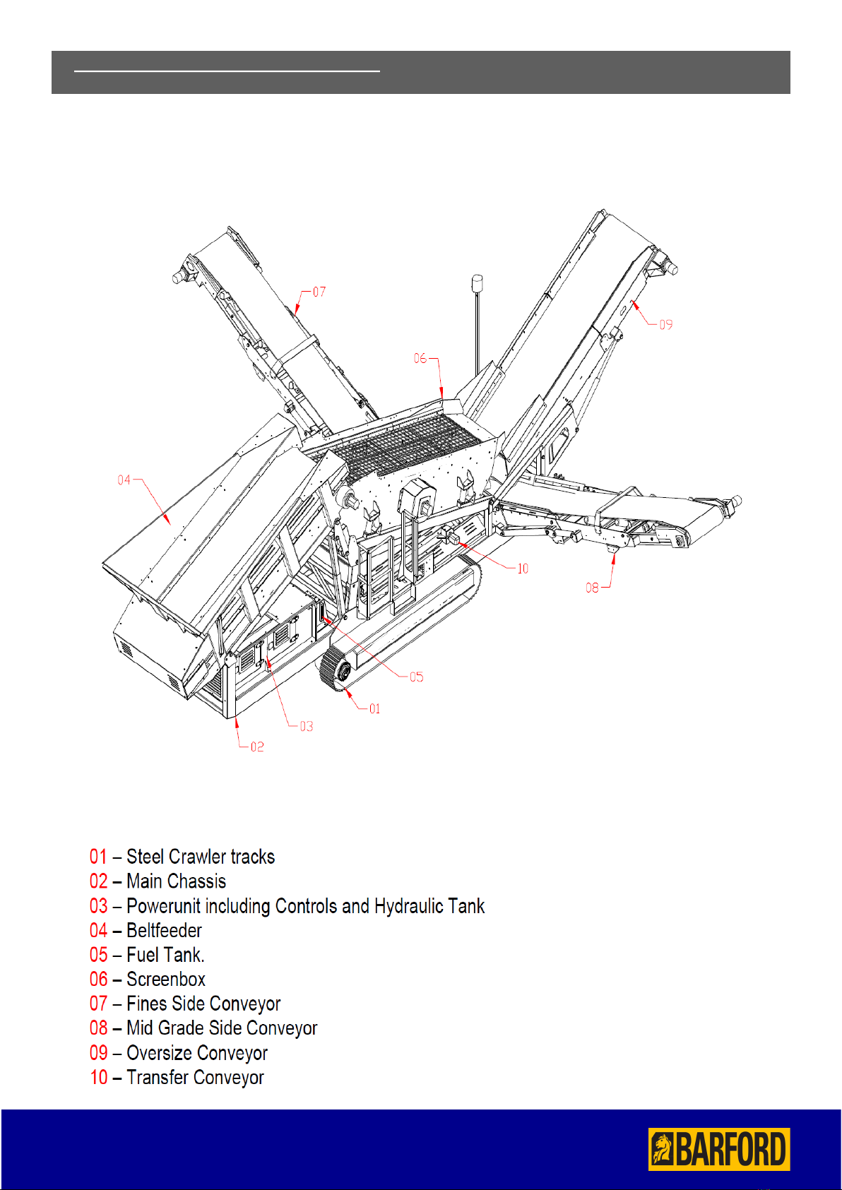
THE POWER UNIT
The power unit is attached to the screeners axle/chassis assembly. The unit provides the power output for the screeners
operations. The unit contains the control panel, throttle, operation valves, feeder, oversize conveyors, flow control valves and the
auxiliary control valve bank.
6) POWER UNIT AND CONTROL VALVES

16
MODEL SR124
16
6) POWER UNIT AND CONTROL VALVES CONTINUED

17
17
MODEL SR124
HYDRAULIC TANK INDICATOR AND RETURN LINE FILTER
The indicator is located at the side of the hydraulic tank, the return line filter is located on the top of the hydraulic tank.
SHUT DOWN OF DIESEL/ELECTRIC POWERED CONVEYOR
•Observe all safety warnings. Make sure the conveyor is empty and clear of all materials.
•Empty the conveyor.
•Lower the engine revs by lowering the hand throttle.
•Stop the main conveyor unit.
•Stop the engine.
OVERSIZE AND FEEDER CONVEYORS FLOW CONTROL VALVES.
•In Addition to the control valves your machine is fitted as standard with a variable speed control for the Feeder/Oversize
conveyor. It is located inside the power unit.
•This is clearly labeled and should be used to adjust the feed rate of material onto the Screen box. The Belt feeder feed rate
will be different in each application depending on the raw material to be screened to maximize throughput and screening
efficiency.
6) POWER UNIT AND CONTROL VALVES CONTINUED
18
MODEL SR124
18
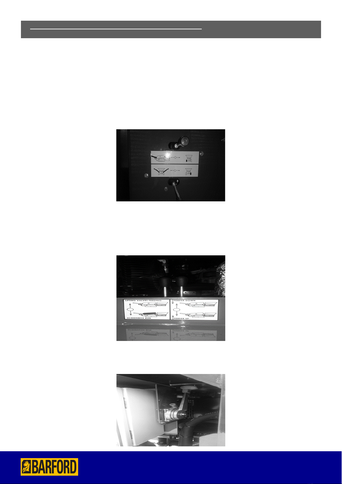
CONTROL VALVES AND HAND THROTTLE
The control valves are contained in the power unit.
The two single lever valves has three main functions;
1. Running the Conveyors.
2. Neutral Position
3. Track Position (right hand of operator) This allows the screener to be tracked.
Double lever valve has three main functions;
1.This position activates control valves for side conveyors and oversize conveyor/lower feeder conveyor.
2.Neutral Position
3.Run the screen unit/raise feeder conveyor (towards operator)
The hand throttle has two functions, to increase and decrease engine speed. To increase power, pull the lever towards the opera-
tor. To decrease push the lever away from the operator.
6) POWER UNIT AND CONTROL VALVES CONTINUED

19
19
MODEL SR124
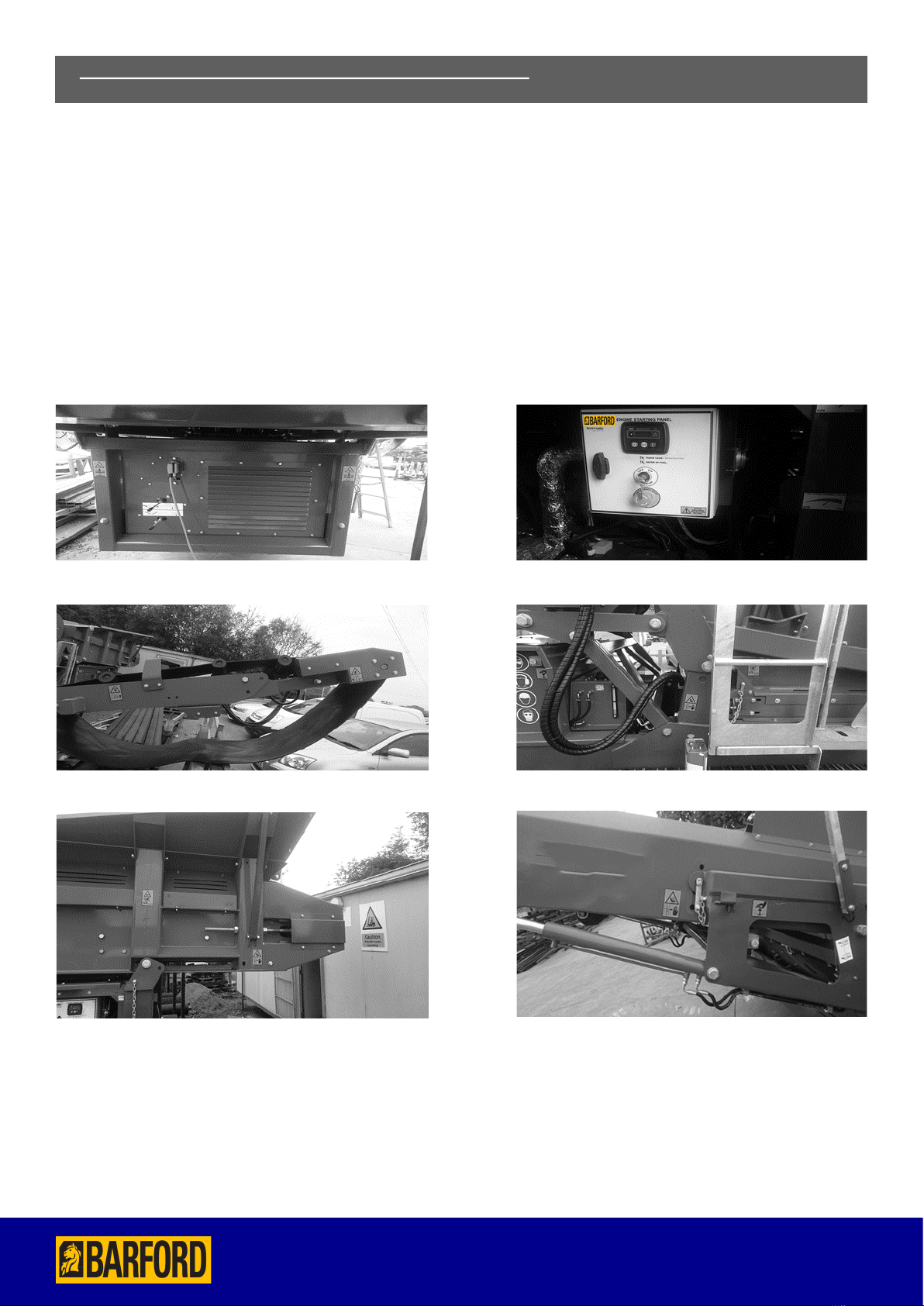
CONTROL VALVES LOCATED ON A BOTH SIDES OF CHASSIS
FINE CONVEYOR
The two four lever valves has three main functions;
1.Unfold. This allows to fold/telescopic section slide in
function.
2.Neutral Position.
3.Fold (toward operator) This allows to fold/telescopic
section slide out function.
MID CONVEYOR
The two four lever valves has three main functions;
1.Unfold. This allows to fold/telescopic section slide in
function.
2.Neutral Position.
3.Fold (toward operator) This allows to fold/telescopic
section slide out function.
CONTROL VALVE LOCATED ON A LL SIDES OF CHASSIS
OVERSIZE CONVEYOR
The single lever valve has three main functions;
1.DOWN/FOLD This allows to down/fold
Conveyor function.
2.Neutral Position.
3.UP/UNFOLD (toward operator) This allows to
up/unfold conveyor function.
6) POWER UNIT AND CONTROL VALVES CONTINUED
20
MODEL SR124
20
Observe all safety warnings.
To leave the conveyor ready for operation it first has to be changed from transit mode.
To do this the following steps must be followed;
1) Remove Track / trailer securing chains.
2) Connect Dog lead track control (or Activate Optional Radio Remote).
3) Start Engine and keep on low idle. (See section 3D).
4) Set hydraulic control levers to send power to tracks.
5) Unload machine from Trailer unit.
6) Unfold Side conveyors slowly moving each section a little at a time.
7) Extend side conveyor top telescopic section and pin into position.
8) Raise feeder plus Screen sub frame and pin into position.
9) Raise Oversize conveyor and pin into position.
10) A level operating surface must be provided to meet this machine’s running requirements. The machine can then be
Tracked into its required location.
TO RETURN BACK TO TRANSIT MODE, DO STEPS IN REVERSE ORDER
7) CONVEYOR IN TRANSIT TO WORKING POSITION
Table of contents
Other Barford Industrial Equipment manuals

Popular Industrial Equipment manuals by other brands


Forstreich Maschinenbau
Forstreich Maschinenbau Spiral Cone SK50 Original operating instructions

Magnescale
Magnescale MJ100 manual

Cognex
Cognex In-Sight IS3808M Reference manual

Eaton
Eaton RMQ-Titan C22-PV Series Original operating instructions

Happy Babies
Happy Babies HAPPY SZ05-A P Assembly instructions

R.V.R. Elettronica
R.V.R. Elettronica TJ5KPS user manual


