BARIX Retail Player S400 User manual

User Manual RetailPlayer
Introduction
What is RetailPlayer?
Applications
About this manual
Additional documents and support
RetailPlayer S400 / SP400
Interesting Fact
Technical Specifications
Connecting the RetailPlayer S400/SP400
Retrieve the IP address using the Sonic IP® function
Retrieve the IP address using the Discovery Tool
The web user interface
The Settings Page
Main application and failover playlist settings
Playback Priorities
Network Settings - Ethernet
IMPORTANT
Network Settings - Wireless
List of devices tested and working with RetailPlayer
DNS, SonicIP® Volume
Proxy Configuration
Time Settings
Security Settings
Status Page
Logs Page
Defaults Page
Reset to factory defaults - Soft reset
Reboot Page
The RetailPlayer Portal
Portal Login
Devices management
Device registration
Device Settings
Device Control
Device Status
Automation
Opening Hours Scheduler
Weekly Streaming Channel Scheduler
Asset Scheduler
Trigger Sets
Remote Control
Channel Management
Create a new channel
Channel Lists
Add channel lists
IMPORTANT
How to play only tracks
Audio Files
Audio Files Manager
Info
Audio Files Scheduler
How to schedule audio files
IMPORTANT
Audio Files Triggers
How to create a trigger set
Organizations management
Users management
Add new user
User privileges
User Settings
Logout
RetailPlayer Security Information
Encrypted Communication with client certificates
Unique Password for every device
Latest Linux Based Software
Barix firmware and Malware
Compliance and further Information

1.
2.
Introduction
The aim of this document is to guide the user through the functionalities of the RetailPlayer. The document describes the elements of the
RetailPlayer solution in detail, explaining the characteristics and functionalities of every single button, led, web page etc. thus elevating the user’s
knowledge of the product.
What is RetailPlayer?
RetailPlayer from Barix is a multi-site, multi-channel streaming platform for background music distribution and message scheduling playback.
RetailPlayer offers the possibility to operate in 2 main modes: Portal mode or stand-alone mode, the first is a cloud-managed solution, the best
choice when there are multiple devices installed in different geographical locations, configured, controlled and supervised from a central web app,
while the second mode is more suitable in those situations where it is enough to have a simple background music system, easy to install and
connect, but not remotely managed.
The solution encompasses 2 key elements:
The RetailPlayer Devices - compact and robust audio decoders, easy to install, connected to the network, and to the amplification
system through standardized connections. When used in stand-alone mode this is the only element of the system
The RetailPlayer Portal - Cloud-based management solution where an organization can register the RetailPlayer devices and control
them at once with an extremely easy-to-use interface
Below is a diagram representation of the solution when used in Portal mode:
In Portal mode, the devices are set to contact the Portal and retrieve their configuration from it (streaming channels, volume, scheduling
information and much more). This is the default mode when the RetailPlayer is first operated
In stand-alone mode, the RetailPlayer devices do not connect to the Portal and are configured singularly via their own web user
interface. It is possible to configure a device in Portal or stand-alone mode in its web user interface
Applications
RetailPlayer is suitable for:
Distributing background music (e.g. in retail stores, restaurants, gyms, hotels, etc.)
Radio distribution systems with central management
Corporate audio streaming solutions
Music on Hold systems
About this manual
This manual is intended for distributors, installers and users of the RetailPlayer solution. It explains the functions of the RetailPlayer device, how
to set up the connections, how to configure the system in Portal and in stand-alone mode, how to access the Portal, and use all of its functions
and features. This manual is easy to read by anyone with some basic knowledge of networking and computer science.
This manual assumes that the firmware installed on the RetailPlayer device (S400 or SP400) and the portal versions are the latest releases.
(check out the for information on the release history and change log)release notes
Barix always recommends to run the latest firmware available and provides a dedicated download area for registered users on www.barix.com
, the RetailPlayer downloadable items are under Products – Decoder or simply type in the search bar at the top of the page/downloads
“RetailPlayer”, the downloadable items for the RetailPlayer will appear.
RetailPlayer offers the possibility to update its firmware locally from its web user interface or remotely from the Portal (more details in the Update
section)Page
The S400 and the SP400 are the decoder devices on which it's possible to run the RetailPlayer firmware. The main difference between
the 2 is that the S400 is powered via a 5VDC power supply, while the SP400 is powered via PoE.

Additional documents and support
The following additional documents are available for the RetailPlayer Solution:
RetailPlayer - Quick Install Guide: In this document are explained the fundamental steps required to have RetailPlayer quickly up and
running on an S400 decoder with an overview on the device, on the Portal and stand-alone modes. This document is available online at
under the RetailPlayer product menuwww.barix.com/downloads
RetailPlayer articlesKnowledge Base
RetailPlayer S400 and SP400 product sheets: These documents are available for download on the Barix website for all users in the
download area . The S400 and the SP400 are the decoder devices on which the RetailPlayer firmware canwww.barix.com/downloads
run. The main difference between the 2 is that the S400 is powered via a 5VDC power supply, while the SP400 is powered via PoE
Each product from Barix comes with a printed Quick Install Guide offering an overview on the physical interfaces and how to connect to
the device for the first time
Beside checking regularly the Barix website and the Barix help, the user has access to support in several ways:
Check with your local distributor for the technical support they offer. A list of distributors is also available on the Barix website at
this link
RetailPlayer S400 / SP400
The RetailPlayer S400 and SP400 are audio over IP decoders. They are used to run the RetailPlayer firmware playing out the configured audio
streams (or channels) and connecting to the amplification system. In the following chapters are described in detail: their physical connections and
their web user interface's functions.
Both the S400 and SP400 are ultra-compact and sturdy devices that can be easily installed anywhere by almost anyone. Little maintenance is
required. The MTBF (Mean Time Between Failures) value of 200’000 hours (almost 23 years) gives an indication of how reliable these devices
are.
The only difference between the S400 and the SP400 is the way they get powered. The S400 receives power from a 5 VDC power supply unit,
shipped with the device, while the SP400 receives the power directly from the network switch using Power over Ethernet (IEEE 802.3af PoE), this
simplifies installation by minimizing cabling requirements while flexibly enabling the units to be installed in locations without an available power
outlet.
In both cases the devices are made to consume a little amount of power (max. 4 watts), running on low voltage circuits.
Technical Specifications
S400 SP400
Rear panel
Power socket Barrel 3.5 x 1.05 mm female connector 5 VDC / 2A input
power (positive polarity) NA
LAN RJ45 – 10/100 Ethernet Interface RJ45 – 10/100 Ethernet Interface with IEEE802.3af PoE
LAN Led LAN yellow LED: Activity
LAN green LED: Link / Speed (blinking)
Front panel
Audio Line out 3.5mm (1/8”) stereo jack. (Tip = Left | Ring = Right | Sleeve = gnd)
Interesting Fact
For users of the Barix Exstreamer Streaming Client product, it is interesting to notice that the RetailPlayer devices, based on the new
Barix IPAM400, offer a significantly higher buffer size, thus ensuring a longer play-out (60s) in cases where the network connection is not
as stable.

Reset button Hold for 3s: reboot the device
Hold for 10s: reset to factory defaults
Status Tri-color LED with the following functions:
1- Red blinking fast: early startup
2- Red blinking slow: system boot
3- Red solid: 1 stage boot loader
st
4- Green solid: system up and running
5- Green blinking: restoring factory defaults
6- Orange blinking: firmware upgrade in process
7- Orange steady: Operating System failed to load
EXT. USB (x2) Type-A USB connection used for:
WiFi Dongle (Supported chipset: Realtek RTL8188EU - List of devices: )click here
Play FROM USB functionality
Failover playlist in stand-alone mode (.mp3 audio files) loaded into a USB drive (/ root folder)
Technical Specifications
OS Embedded Linux based on Yocto
Network IPv4 / IPv6 capable
full-duplex / half-duplex
auto-negotiation
Protocols: TCP/IP, UDP, RTP, HTTP, HTTPS, DHCP, NTP, DNS
Audio Formats MP3 (CBR/VBR) up to 320 Kbps, 8..48KHz sampling frequency
HE-AAC, HE-AAC+ V2, AAC, AAC+
Opus, Ogg Vorbis
Linear PCM 16bit 44.1kHz stereo big endian
CPU Barix IPAM400 processor module
Quad-Core ARM Cortex™ A7
User Interface Web user interface for configuration
RetailPlayer management Portal
Memory 2GB DDR3 SDRAM
16MB SPI Flash
8GB SD-Card Flash
Power requirements 5VDC, 10 Watt max. IEEE802.3af PoE
Dimensions 78mm x 70mm x 26mm / 3.07” x 2.76” x 1.02”
Weight 140g
Connecting the RetailPlayer S400/SP400
The RetailPlayer offers the possibility to connect to the network via ETH (Ethernet) wired interface or via WLAN wireless interface with the
support of a WiFi USB dongle (Supported chipset: Realtek RTL8188EU - List of devices: ). The first setup of the device should be doneclick here
using the ETH wired interface since it is necessary to access the web user interface of the device to configure the WLAN settings.
The RetailPlayer is configured to be a DHCP client by default.
Please note that the RetailPlayer uses a Web Secure Socket connection in order to communicate with the RetailPlayer Portal. To run smoothly
within a LAN the following ports need to be available for communication with the RetailPlayer services:
Port 80 -> HTTP
Port 443 -> HTTPS
Port 123 -> NTP
Port 53 -> DNS

1.
2.
3.
4.
5.
6.
For more details on the network connections established by the RetailPlayer devices to the outside world, see this Knowledge Base page.
Retrieve the IP address using the Sonic IP® function
Connecting the RetailPlayer devices to the amplification system and to the network is a matter of seconds. The RetailPlayer S400 and SP400
come with a function made by Barix called “Sonic IP®”, meaning that when you boot the device and this is connected to a network where a
DHCP server is present, the device will acquire an IP address and announce it over the audio output. This function is useful when you connect to
the device for the first time and need to access its web user interface.
If the RetailPlayer devices are controlled via the Portal, you can skip this chapter and go directly to the . When theRetailPlayer Portal chapter
device is powered for the first time it is set to contact the Portal, where, after having registered the device, it is possible to visualize the IP
address of the same. For a thorough understanding it is in any case suggested to read the following chapters about the RetailPlayer S400 and
SP400.
Using a Y-type audio cable, connect the 3.5mm (1/8”) connector to the line out of the RetailPlayer. It is also possible to connect
headphones to this audio output.
On the opposite side of the cable, the 2 connectors carry the left and right signals of the stereo stream. Connect those to the input of the
amplification system/mixer/DSP unit.
If you need to hear the IP address during boot (Sonic IP® function), rise the volume of the amplification system
Connect the network cable. If you are using SP400, the device will boot as soon as it receives the PoE. Listen to the Sonic IP®
announced
If you are using S400, connect the power cable to the power connector. The device will boot as soon as the current is flowing. Listen to
the Sonic IP® announced
Boot is finished when the LED is solid green (Portal connection established) or blinking (Portal connection not established, but device is
ready)
Retrieve the IP address using the Discovery Tool
Other than the Sonic IP® function, there are other ways to find out a Barix device’s IP address. One is by using the Discovery Tool from Barix.
The Discovery Tool is freely available for download from , in the download area under Products - Tools. In the samewww.barix.com/downloads
area is available a complete installation guide.
The Discovery Tool is written in the Java programming language, so it requires a Java Runtime Environment (JRE) installed on your computer. If
you do not have a JRE installed, you can download and install it from: Java run time environments arehttps://www.java.com/en/download/
available for many major operating systems. If you are running the Discovery Tool on a Linux or UNIX platform, the Discovery Tool also requires
the X-window graphical user interface.
The Discovery Tool is distributed in a Java Archive (.jar) file. On most operating systems you can run the Discovery Tool by simply double-
clicking on the discover.jar file. On most operating systems you can run the Discovery Tool by simply double-clicking on the discover.jar file.
Click the "Get" button to initiate a search. If the Discovery Tool finds one or more RetailPlayer devices on the network each device is listed in the
table, including its current IP address, MAC address (labeled "Ethernet Address" in the Discovery Tool), firmware version, and other information.
IMPORTANT: Before connecting to the amplification system, make sure the volume of your system is lowered at minimum or completely
switched off to avoid potential damage to the system.

1.
2.
3.
The Discovery Tool should find any device that is on the same network as the computer running the tool, regardless of their current IP address
setting. The tool will not search through a router to another subnet.
You can use the address that appears in the Discovery Tool to access the RetailPlayer device via a web browser. However, keep in mind that the
IP address could change if the RetailPlayer is rebooted.
You can also set the address in the Discovery Tool by double-clicking on the IP address field of the RetailPlayer device you wish to change.
When you double click the address field, the IP address field will become editable. Enter the IP address you want to assign. Then click "Set", the
"Set reply" field should say "No error" if the address assignment was successful.
If you decide to assign the RetailPlayer device a static IP address, you must be sure to use an address that is outside the range of addresses
that are automatically assigned by any DHCP server on the network.
The web user interface
With the IP address of the device is possible to connect to the web user interface.
Open a web browser and type the IP address in the URL field.
By default, when the RetailPlayer decoder is started for the first time, it is configured to run in Portal mode, which means that its configuration is
managed by the Portal.
In the following paragraphs, the settings and the different sections of the web user interface are described.
The Settings Page
As soon as the web user interface is accessed it visualizes the SETTINGS page.
The window is organized in:
The top navigation bar (settings, status, logs, defaults, update, reboot. In addition on the top right corner there are the MAC address and
current firmware installed on the device)
The operational area. Where the user input values and set parameters
The side help section, which offers a brief overview on the parameters and values helping the user without the need to leave the page.
TIP: Each parameter has a default value, those values are also reported in the help section.
Main application and failover playlist settings
This section is used to configure the main operational mode of the device, either if in Portal or stand-alone.
Portal Stand Alone
Discovery Tool is able to retrieve the IP address of RetailPlayer devices wired to the network over the ETH LAN interface. it is not
possible to retrieve the IP address of a device connected to the network using WLAN interface (WiFi USB dongle)
To access the the web user interface of the device the "Webconfig" flag on the Portal must be checked. This option can be found in Devic
See image below. More details are provided in the chapter of this manual.es Basic Settings Device Webconfig. RetailPlayer Portal

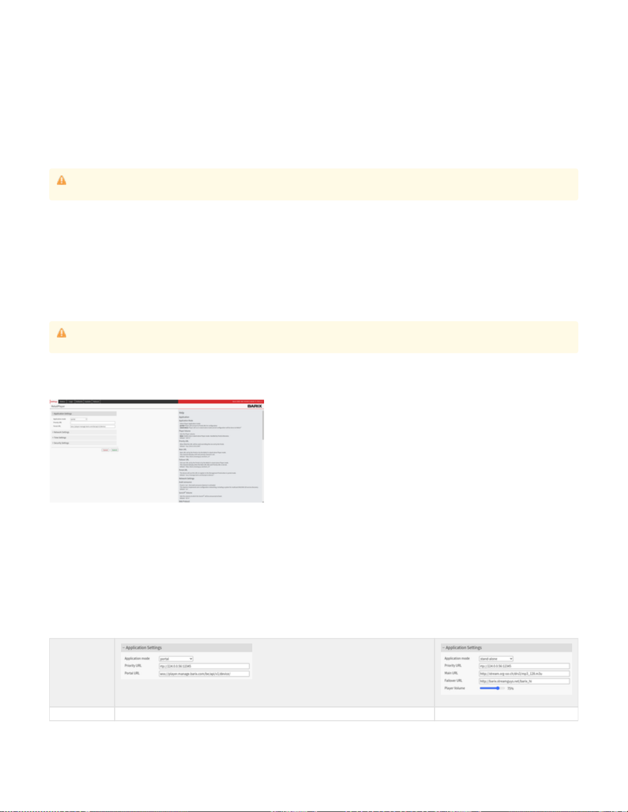
Application Mode Set the RetailPlayer device to run in Portal mode. This means that the device will connect to the Portal
indicated in the Portal URL field. By default is set the Barix Portal endpoint: wss://player.manage.barix.com
/be/v1/api/device/
In this mode, the device will contact the Portal retrieving its configuration settings from the same.
Set the device to run in stand-alone mode.
This means the device will not connect with
the Portal. In fact, the field “Portal URL” is not
shown if stand-alone mode is selected. In
stand-alone mode, the following values are
required and visualized: Player Volume, Main
URL, Failover URL, Failover Server URL. In
this mode the player works as a "stand-alone"
decoder.
Priority URL The priority URL is used in both Portal and stand-alone mode but it is only configurable from the web interface of the RetailPlayer. It is not possible to
configure the priority URL from the Portal. The Priority URL will play over anything that is currently being played by the player. By default is left empty**,
example of configuration is , useful if the need is to send an advertisement or a message to a specific group of devices, overriding thertp://224.0.0.56:12345
background music played by the Portal or by the main URL (if used in stand-alone mode) or any message scheduled and that might play.
The device supports the following protocols: RTP, HTTP, HTTPS. It supports multicast, unicast or broadcast addresses.
When the Priority URL is configured to play an RTP Multicast stream the device sends an IGMP Join request to the appointed address. In Managed switches
it is normally possible to modify the IGMP settings to control the entries, the requests, the IGMP carriers and monitor which ports are joining a specific
Multicast group.
Portal URL Available in Portal mode only. It is the Portal URL to which the device has to connected to be configured. In
this mode, it is also possible to avoid accessing the web user interface of the RetailPlayer device, instead
use the Portal to configure the settings.
This mode is the key feature of RetailPlayer as it enables the configuration and management of multiple
devices from a central location with ease.
The connection with the Portal is established over HTTPS upgraded to Web Secure Sockets
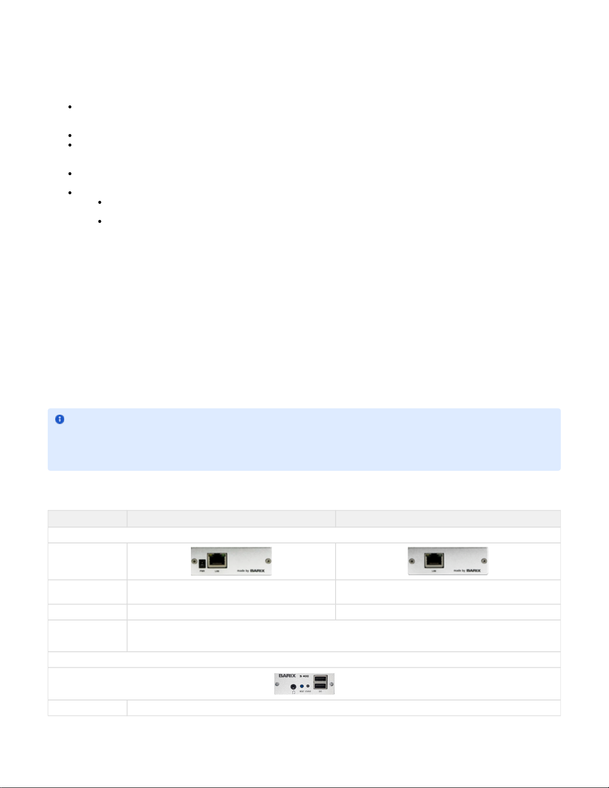
In stand Alone Mode there is no Portal URL.
The main audio stream must be indicated in
the main URL field.
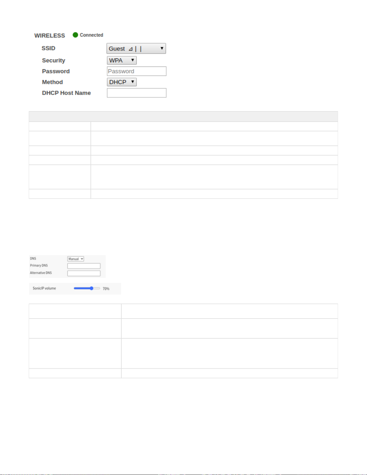
Player Volume In Portal mode, the volume is set from the Portal. Only available in stand-alone mode. It sets the
output audio volume in percentage from 0 to
100.
Main URL In Portal mode, the Main URL is set from the Portal's channel configuration Only available in stand-alone mode. It is the
URL from which the device expects an
incoming stream to be played.
The device supports the following protocols:
RTP, HTTP, HTTPS, it supports multicast,
unicast or broadcast addresses, and MP3,
PCM or AAC audio formats.
Failover URL In Portal mode, the Failover URL is set from the Portal's channel configuration Only available in stand-alone mode. If the
main URL is not received and there is no
priority stream, the device will activate the fail-
over URL. It is basically a backup stream to be
played in case the other streams are not
available.
The device supports the following protocols:
RTP, HTTP, HTTPS it supports multicast,
unicast or broadcast addresses, and MP3,
PCM or AAC audio formats.
Failover playlist settings*
Fallback Tracks In Portal mode, it is possible to set Fallback tracks, which are MP3 files that are downloaded in the device
when it connects to the Portal. Those tracks are played in absence of any of the previous streams (Priority,
Main, and Failover).
In stand-alone mode, the RetailPlayer
supports the possibility to play a failover
playlist from a USB drive connected to one of
its ports. The following considerations must be
taken into account:
The USB drive should be formatted in
FAT32
The audio files must be in .mp3 format
The audio files must be located in the
root folder of the USB stick. Different
files or folders are ignored by the player.
In case the priority the main and the failover
URLs are not available the player will playback
the tracks in the USB drive. As soon as one of
the URLs become available the one with the
highest priority starts to play immediately
stopping the audio track played from the USB
*: This option is not part of the web user interface as it is a built-in function that doesn't require user's configuration, but it is described here for
topicality reasons.
**: In FW releases older than 6.2.1 the default Priority URL is rtp://224.0.0.56:12345 - Those devices running an old FW by default are generating
an IGMPv2 join request in the network once every 10 seconds. In newer FW the Priority URL is empty.
Playback Priorities
The playback sources available on the RetailPlayer platform when in Portal Mode can be summarized following their playback priority in:

Priority Source name Description
1 Priority Stream When received it plays on top of all other sources
2 USB Tracks This feature is controlled by the Portal ( activated from the Settings tab of the Device page). If aPLAY from USB
USB is plugged and the option is active, the device will play the USB tracks on top of all other sources but not
over the Priority URL.
In Stand alone mode: this function works the same as "failover tracks", so the priority is modified and the USB
tracks are played only in case, Priority, Main and Fallback Streams are not available.
3 Events (scheduled or
manually triggered) This source describes the audio files playback (messages, announcements, ads) that can be either scheduled or
played manually from the Portal. The features related to audio files are available only from FW V6.x onward.
When an audio file is scheduled or it is manually triggered it plays over the main stream, the fallback stream and
the failover tracks, but not over the USB tracks (if active) and the Priority URL (if audio is received there).
The schedule and the manual trigger have the same priority, meaning that if I can trigger an audio file to play over
a scheduled file and vice versa.
4 Main Stream The main stream plays over the fallback stream and the failover tracks only. It is overlapped by the audio files
scheduled or manually played, the USB tracks (if active) and by the Priority URL.
5 Fallback Stream The Fallback stream plays only in absence of the main stream. It is not mandatory but useful in case the user
requires a failover mechanism in case the main stream goes down.
6 Failover Tracks The failover tracks are the audio files uploaded in the Portal when a channel list is created. Those tracks are to be
used as the last playback source in case no other source is available to play. They are downloaded by the device
one by one when the channel list is assigned to the device in the Portal. If a channel list is already assigned, the
failover tracks can be modified in real time and the device will update the tracks when the user saves the modified
channel list. The maximum number of failover tracks supported per each channel list is 200.
Network Settings - Ethernet
In this area, it is possible to configure the RetailPlayer device’s network settings. Dynamic or static address assignment methods can be
configured for the Ethernet interface.
The RetailPlayer supports the Dynamic Host Configuration Protocol (DHCP), which allows the device to acquire an IP address available from a
pool of addresses hosted by a DHCP server. It is the server that offers an IP address to the device when discovered on the network. The IP
address offered by a DHCP server comes with a lease time, meaning that when the leased time is over the DHCP server re-issues the IP
addresses to the devices on the network, with the possibility that it might assign a different address than the one assigned previously. In addition,
the DHCP server provides all associated information to the requesting device, such as subnet, gateway, and DNS addresses.
While DHCP is a convenient way of assigning IP addresses, there are situations where it is necessary to assign static addresses at devices on a
network, that must be the same over time, that is why it is also possible to set a static IP on the RetailPlayer device.
DHCP Method Static Method
IMPORTANT
While it is possible to use DHCP or Static IP methods for assigning an IP address at the Ethernet (wired) interface of the RetailPlayer it is
not possible to do the same with the wireless interface, which supports only the DHCP method. If you run your RetailPlayer using solely
Wireless connection (no Ethernet cable plugged), make sure to set the Ethernet method field to failing in doing so will result in theDHCP,
impossibility to connect your device to the wireless network.

1.
2.
3.
4.
5.
6.
7.
8.
DHCP Hostname
When DHCP is the chosen protocol it is possible to indicate the Hostname
of the DHCP server to be sent in the DHCP request. It's an optional field.
IP Address
It is the fixed IP address of the RetailPlayer device. The IP address is the unique
identifier of a device on a network, in case of static assignment make sure that no
other device on the same network has the same IP address assigned to the
RetailPlayer
Netmask
In addition to the IP address, it is mandatory to provide information about the
subnet mask. The subnet mask indicates which bits in the IP address are used
for the network portion and which bits for the host portion. It is common in Class
C LAN to see 255.255.255.0, this configuration indicates that the first 3 octets of
the IP address (e.g. .100) are dedicated to the network identification,192.168.1
while the last octet (e.g. 192.168.1. ) is dedicated to the host identification on100
the network
Gateway IP Address
The Gateway IP is the address of the device that bridges your Local Area
Network with the Internet. Typically is a router where devices on a LAN are
connected. For using the RetailPlayer in all its cloud-based features, but also to
receive a stream from an internet radio in stand-alone mode, for example, it is
essential to provide this address. If you are not sure about the Gateway address
in your network contact your network administrator
Network Settings - Wireless
RetailPlayer devices are equipped with 2x USB ports in the front panel that can be used for a WiFi Dongle to be connected, in this way the device
can connect to the network wirelessly. It is necessary to configure the wireless parameters to access the WiFI network.
To connect your RetailPlayer to a wireless network:
Insert your WiFi USB dongle in one of the USB ports (no matter which one you choose)
Refresh the web user interface from your web browser or if your device was powered off, power it on. You should now see an indication
stating "not configured" close to the WIRELESS label
Select the SSID to which you intend to connect to from the drop-down list
Set the Security protocol to WPA
Insert the password for the SSID selected
The method for IP assignment is set to DHCP, in the firmware version 5.3.0, static IP assignment is not available for the WLAN interface.
Make sure that also the Ethernet method is set to DHCP or your device will not connect to the wireless network
Click on Submit at the bottom of the page. The device will apply the configured settings and will reboot. After reboot, the WiFi status
should be connected, indicated by a green dot next to the WIRELESS label. Visit also the Status page of the web UI and locate the
Wireless settings, here you can check the IP address configured on the device, mark it down if you intend to access the device via WiFi
Switch off the RetailPlayer and detach the Ethernet cable, power it back on, wait until boot process is over (if Sonic IP is on it will
announce its IP address over the audio output) and verify that the wireless connection is fully working
When the device connects correctly to a wireless network it will be indicated in the web UI as follow:
NOTE: RetailPlayer devices are compatible with the Realtek RTL8188EU chipset. for the full list of compatible vendors andClick here
product IDs.
While it is possible to use DHCP or Static IP methods for assigning an IP address at the Ethernet (wired) interface of the
RetailPlayer it is not possible to do the same with the wireless interface, which supports only the DHCP method. If you run your
RetailPlayer using solely Wireless connection (no Ethernet cable plugged), make sure to set the Ethernet method field to DHCP, f
ailing in doing so will result in the impossibility to connect your device to the wireless network.

1.
2.
WIRELESS
Connection LED It shows the status of the connection to the wireless network and if a dongle is inserted and configured
SSID It is the Service Set Identifier or the name of the wireless network you intend to connect to or if already connected, it's the one
that you are currently using
Security Select the correct security protocol to be used
Password Insert here the password to authenticate within the wireless network*
Method Define the Dynamic Host Configuration Protocol. For the wireless interface of the RetailPlayer, only the DHCP method is
available.
IMPORTANT: If you intend to connect only using the wireless interface make sure to set also the Ethernet method to DHCP
DHCP hostname It indicates the hostname to be sent in the DHCP request. It is an optional field.
List of devices tested and working with RetailPlayer
TP-Link TL-WN722N
Realtek RTL8188EUS
DNS, SonicIP® Volume
Completing the network configuration of the RetailPlayer device are the below settings:
DNS Auto Automatic Domain Name System resolution. If set in Auto the DHCP server will provide the address of a DNS
server to contact for the IP name resolution process.
DNS Manual If DNS is set to Manual the device expects the Primary and Alternative DNS server fields to be filled with the
related information. When Ethernet IP method is set to Static, DNS will always be set Manual and it is
mandatory to provide the address information
Primary DNS and Alternative DNS This address is for the Domain Name Server. It tells the RetailPlayer which DNS server to contact to resolve
domain names into IP addresses. I.e the address of an internet radio like http://barix.streamguys.net/Barix_hi
has to be translated into an IP address, this is the job of the DNS server. The alternative DNS is a backup
resolution in case the primary DNS server is down. The alternative DNS is not a mandatory field. If you are not
sure about the DNS Server address to be used, contact your network administrator.
SonicIP® Volume Sets the volume of the Sonic IP® announcement.
Proxy Configuration
Available from FW version 6.2.0. It allows the RetailPlayer to become "Proxy" aware so that the RetailPlayer can be deployed in those
enterprises where network connections within the LAN must go through a Proxy.
Proxy type supported: HTTP

Host Insert here the Hostname or the IP Address of the Proxy
Port The port number used by the proxy to listen for incoming connections
User name If the proxy requires authentication, inset here the username to be used,
otherwise leave the field empty
User password If the proxy requires authentication, inset here the password to be used,
otherwise leave the field empty
Exceptions* Set here any proxy exception, connections that will bypass the Proxy
NOTE: This function is available from FW V6.2.1 onward
Time Settings
It's important that the RetailPlayer device operates running the correct date and time. This is because the validation of HTTPS certificates used to
establish a secure connection with the Portal requires the certificate to be valid for a time window. The devices uses its system time to present
the certificate to the Portal, if this time is not within the time window expected the device fails in establishing the connection with the Portal.
The RetailPlayer devices use an NTP daemon to set their system time. The NTP protocol is used on the standard port 123. The time set by NTP
is in UTC.
On the web interface, the time settings allow the user to change the default NTP pools used by the device. This is because in some situations,
customers might be using their internal NTP servers, or they simply prefer to use others. The fields accept either a domain name (which requires
a valid connection to the DNS to be able to associate an IP Address to the DN) or an IP Address.
It is possible to check the system time in the Status page of the device, or from the Portal status page.
NTP is used to set the time only at device boot, when the connection with the Portal is established, the time is set by the Portal, where it is also
possible to choose the Time Zone where the device is installed to set the time accordingly.
Security Settings
This area is dedicated to secure the login to the RetailPlayer web user interface device and to enable or disable the possibility to run critical
operations: reboot, reset to factory defaults and update
Reboot Function Enable or disable the reboot function of the device from the web UI
Reset Factory Defaults Enable or disable the possibility to reset the device to factory default from the web UI
Update Function Enable or disable the possibility to update the device from the web UI
Web UI Password Set the password to access the web interface of the RetailPlayer device. If a password is already set another field is displayed:
OLD PASSWORD, which is required to change the password again
By default the device web interface is protected by the password printed on the backside of the device itself. It is also possible
to avoid access to the web interface by disabling the webconfig option from the Portal settings, thus disabling the device web
browser.
default username: admin
Additional Certificates* Allows the possibility to upload custom .crt certificates to the device. Useful when the device is used in private enterprise
networks where a private CA is in place to validate secure connections between devices.

*Only available from FW V6.3 onward
SUBMIT
By clicking on the button SUBMIT all the changes made in the SETTINGS page are applied in the configuration.
By clicking on CANCEL all the changes are not applied and the fields return to their previous inserted value.
Status Page
On the top navigation bar click on STATUS to visualize the current status of the RetailPlayer device. The status report offers device information
on the hardware and the application status. It’s a quick overview of the RetailPlayer device's current configuration.
The Status Page displays the following information:
Application Status
Portal URL The current portal URL configured in the settings page
Active stream The audio stream that is currently playing. It is a useful indication to verify if it is playing any stream among priority, main, failover or
fallback tracks (failover playlist with mp3 files)
Priority stream The priority stream URL configured on the settings page. This is the stream with the highest priority, if it is received it will overlap
any other stream currently playing
Main stream The main stream URL configured on the settings page
Failover stream The failover stream URL configured on the settings page
Current playback
volume The playback volume of the player currently set. If the device is used in Portal mode the volume is set from the Portal, in stand-
alone mode, the volume is set from the settings page
Failover Playlist
Name This is the name of the file saved in the device configuration. It is filled automatically when fallback tracks are identified, eitherplaylist.m3u
from the Portal, when the device is used in Portal mode or from the USB drive, when used in stand-alone mode
Content The actual fallback tracks (mp3 files) the device will play in absence of any stream provided. This field is useful to verify if the fallback
tracks uploaded from the Portal are actually retrieved from the device
NOTE: When the tracks are retrieved from the Portal the name of the file is the unique identifier used in the Portal to match with the
corresponding resource

Device Information
Hardware type The actual RetailPlayer device (in parenthesis is the Part Number)
IPAM type The Barix IPAM codec module installed in the device (in parenthesis the Part Number of this component)
MAC Address Media Access Control address - This is the hardware address of the Ethernet interface of the device. It is required when the device
is registered on the RetailPlayer Portal. It is found here but also on a sticker applied underneath the device
Firmware version The running firmware installed on the device
Application The name of the application currently running
Linux kernel version The version of the Linux operating system in use
Bootloader version The bootloader version currently in use
Network
Wired Connection
Status Shows if the device is connected via the Ethernet interface to the network
IP Address The current IP address of the Ethernet interface
Netmask The subnet mask on which the device is operating
Wireless Connection
Status Shows if the device is connected via the Ethernet interface to the network
MAC Address Media Access Control address - This is the hardware address of the wireless interface of the inserted WiFi USB dongle
SSID The Service Set Identifier - the name of the wireless network to which the device is currently connected
Signal Strength The power expressed in percentage (0% - 100%) of the WiFi radiation
IP Address The current IP address of the wireless interface
Netmask The subnet mask on which the device is operating
Network
Default Gateway The gateway address currently set
DNS Servers The DNS server addresses (primary and secondary) currently in use. Provided either by the DHCP or entered manually in the settings
page
Try to position the device where this value is higher than 45% to get better results when using a WiFi connection

System Status
System time The device's current local time
Uptime How long the device is powered on
Logs Page
The Logs page displays the events occurring operation of the RetailPlayer device.
Logs are useful for debugging issues, they give a detailed insight into every process within the RetailPlayer OS.
On the top-right corner, it is possible to click the button “ ” to download all log files. Download all messages
Defaults Page
Reset to factory defaults - Soft reset
The defaults page on the web UI of the RetailPlayer device allows performing a soft-reset. Such operation reverts all settings except the network
settings back to factory defaults (it doesn't perform a firmware downgrade, just a reset of the settings for the running application).
The reset to factory defaults can be enabled or disabled from the settings page, under "Security Settings".
When the button is clicked the device starts a 10 seconds countdown, after which it is possible to reload the web user interface.
Reset to factory defaults – Hard reset
On the RetailPlayer device, It is also possible to perform a hard reset. A hard reset will revert all settings to factory defaults including the network
settings.
To perform a hard reset locate the reset button on the front panel of the RetailPlayer device and keep it pressed for approximately 10 seconds
using a sharp-pointed tool while the device is powered. The status led will blink green 3 times, informing that the reset operation is started. After a
few seconds, the device will reboot with factory defaults. Reload the page after the operation is completed.
When contacting the Barix support it is useful to take a screenshot of this page and attach it in the communication along with the Logs
downloaded from the corresponding page. Do not forget to give a description as much detailed as possible about the steps made that led
to the issue.
When contacting the Barix support it is useful to attach along with the communication the Log files downloaded and the status page
screenshot. Do not forget to give a description as much detailed as possible about the steps made that led to the issue.

Update Page
The RetailPlayer platform offers the possibility to update the firmware of the device locally from the web user interface or remotely via the Portal.
More details are provided in this chapter on both functionalities.
The Update page has 3 purposes:
Visualizes the current software loaded on the RetailPlayer device
Enables the remote update of the device
Updates the device directly
Visualize the current version installed
Under “Currently Loaded Version” it is visible the current firmware installed, the root file system version, the web UI release version, the kernel
details, and the Bootloader information.
Remote update via the Portal
The RetailPlayer Portal offers the possibility to update the firmware of the RetailPlayer devices remotely. (More details on how to access the
Device settings from the Portal are provided in the )RetailPlayer Portal chapter
To update the firmware remotely from the Portal:
Login in the Portal at manage.barix.com
Navigate to the Devices menu and select the device from the list on which you intend to run the Upgrade
In the Overview page of the device, under Basic Settings locate the firmware drop-down menu
Select the desired firmware version
If your current firmware is older than 5.2.0: the update will run at 4 am the next morning
If your current firmware is 5.2.0 or newer: the update can run at 4 am the next morning or it can be forced by power-cycling the
RetailPlayer device. At boot, the device will look for the new firmware version and if it sees the value on the Portal changed it will
update the firmware accordingly
In the Portal is possible to set an automatic FW update by selecting from the drop-down menu a ".x" release (i.e. Firmware 6.x). In this way any
release that will be available within the Firmware version 6.x will be installed automatically by the devices, when checking on a daily basis every
morning at 4am if there is an update available in the download server.
Update via the web user interface
To update the firmware locally from the update page, the first thing to do it to download the latest firmware package from the website www.barix.
– The firmware of the RetailPlayer is located under the section Products – Decoder. Alternatively, just type “RetailPlayer” in thecom/downloads
search bar on the web page. The possibility to download firmware packages is available only for registered users.
The firmware comes as a TAR archive file. To update from the web user interface:
In the Update page click on “ ”, the system update page is accessedPlease click here to start the update
Run always the latest firmware available from Barix as it might include bug fixes, improvements or new useful features
in order to update to a firmware version newer than 5.0 from an older firmware it is mandatory to first update to firmware version 5.0 and
then update to the 5.X or 6.x firmware. More on the subject .here
The Device needs to be powered overnight in order to perform the automatic update at 4 am.

Click on “Choose File”, locate and select the corresponding TAR archive
Click on “Upload”
An indication bar will show up indicating the upload process completion. Wait until the process is finished (don't disconnect power supply
during this operation)
Once the upload is complete the device will reboot automatically. Reload the page or click the home link to go back to the home page.

Rescue Image Process
The application of the RetailPlayer runs on a removable flash memory card that comes in a microSD format. There might be cases where the
application cannot be loaded correctly anymore from the flash memory. In this case, it is possible to run a rescue process to restore the original
factory firmware on a new microSD. (i.e. if your device was shipped with firmware 5.2.0 and you were using 5.3.0, by doing this process the
firmware will be restored to firmware version 5.2.0 and all the settings reset to factory defaults, including network settings)
The procedure:
If your RetailPlayer device is powered, shut it off
Make sure the device is connected to internet. For this process to work the device will attempt a connection to Barix Download server via
HTTP (port 80), if successful it will download the rescue image from this server
While the device is off, press the reset button
Keep the button pressed while powering up the device (S400: connect the power cable / SP400: connect the ethernet cable)
Keep the button pressed in for 34 seconds after the device is powered
Release the button, the rescue process starts
The device restarts and the LED will blink orange indicating a FW update/downgrade process is in progress
When the LED will turn green (blinking or steady), reboot the device
Your device now is reset to default to the last Firmware released
Reboot Page
This page is dedicated to the reboot of the RetailPlayer device.
The reboot is the process of power cycling the device (ON OFF ON). It’s a complete power cycle.
The reboot can be performed from the web user interface or from the reset button located on the front panel of the device.
Reboot from the web user interface
Click "Reboot the device" to restart the device. While restarting a screen showing a countdown of 10 seconds appears. At the end of the
countdown, the device is rebooted. Wait approximately 20 seconds and then reload the web page or click on the text shown “click to returnhere
to the home page”.
Please clear the cache or restart your browser to ensure the web interface of your device is displayed correctly after the update.
Do not disconnect the power supply during the update. The software update can take up to several minutes depending on the size of the
firmware.

Reboot from the reset button
The reboot of the device from the button is performed by pressing the Reset button located on the front panel of the RetailPlayer device for 3
seconds approximately.
The RetailPlayer Portal
As advanced in the Introduction chapter of this manual, the RetailPlayer platform involves the possibility to run in Portal mode, a key feature of
the solution. In this mode, the devices are entirely configured and controlled in real-time from the Portal, with the option to control them also via a
web-app accessible with the support of QR codes. More details are provided in the upcoming chapters.
The Portal is accessible using a web browser at: https://manage.barix.com
Portal Login
When purchasing the RetailPlayer solution, get in touch with Barix Support team ( ) or with your local distributor to receive[email protected]
your RetailPlayer Portal credentials, required to login.
In the Login area, enter the credentials.
The first time the Portal is accessed it will ask to change immediately the password used for login.
Insert the new password, confirm by clicking on in the top-right corner. Logout and log back in again with the new password.
Once logged in the Portal, the Device List is visualized:
A long press of this button (10 seconds) will reset the device to factory defaults.

The side-bar menu on the left gives access to the following sections of the Portal:
Organization selector: If the organization in use has one or more sub-organizations, they will be listed in this drop down menu selector.
Changing between different organizations affects the visualization of the resources of the same: devices, channels, channels lists, audio
files schedules and triggers
Devices: the device management section (registration, configuration, control, monitoring of each RetailPlayer device)
Channels: the channels are the stream URLs, this button gives access to the configuration of the channels
Channel list: channel lists are group of channels, this button gives access to the configuration of the channel lists
Audio files: manage audio clips to be scheduled on a weekly scheduler and played by interlacing with the streaming channels or create
trigger sets to play the audio files manually from the QR Code web app or from the Portal directly
Organizations: gives an overview of the main organization and the items belonging to it (sub-organizations, users, devices, channel lists)
Users: the user management section (creation, management, privileges assignment)
In the lower section, on the left, it is possible to visualize the name of the logged user. It is possible to assign a user to multiple organizations and
give to the same user different permissions to access or not the areas on the Portal. If a user is assigned to more than one Organization.
Continue the reading to learn more about how users and organizations are handled.
Devices management
The "Devices" button gives access to the device list. All the registered devices of an organization and its sub-organizations are listed in this list.
To list only devices part of a sub organization select the corresponding sub organization from the drop down menu present in the side bar
The device list is organized as follow, from top to bottom:
Quick Filters with counters and search bar
ONLINE device filter.
Click on this button to list only online devices. The number in the icon represents the number of online devices in the list
OFFLINE device filter.
Click on this button to list only offline devices. The number in the icon represents the number of offline devices in the list
FALLBACK URL device filter.
Click on this button to list only devices that are currently playing the fallback url. The number in the icon represents the
number of devices that are in this condition
FAILOVER TRACKS device filter.
Click on this button to list only devices that are currently playing the failover tracks. The number in the icon represents the
number of devices that are in this condition

Search in the list.
Use this text input field to search for devices in the list. Parameters that can be used for the search: Name, MAC, Location,
Notes.
Refresh the table.
The table is automatically refreshed every 15s but if a quicker refresh is required the user can click on this button.
Device List
Delete device button
Delete a device from the Portal.
Once removed the RetailPlayer is the audio output is silent.muted,
Online / Offline
indicator
Online: the device successfully established a connection with the Portal. It's possible to monitor its status and
control the playback
Offline: the device is not connected with the Portal. If it was connected at least once in the past the reported
information are the last ones reported before disconnecting, if it was never connected there is no reported information or
status. In this state the device cannot be monitored nor controlled.
Opening Hours
indication Open: means the device is Active and receiving the stream
Closed: means the device is Inactive and not receiving the stream (saving bandwidth)
Device is not connected with the Portal
This manual suits for next models
1
Table of contents
Other BARIX Media Converter manuals

BARIX
BARIX TPA400 User manual

BARIX
BARIX EXSTREAMER 100 User manual

BARIX
BARIX Extreamer P5 User manual

BARIX
BARIX Exstreamer 500 User manual

BARIX
BARIX Instreamer User manual

BARIX
BARIX Exstreamer 1000 User manual

BARIX
BARIX EXSTREAMER 200 User manual

BARIX
BARIX Extreamer 1 0 0 User manual

BARIX
BARIX INSTREAMER ICE User manual

BARIX
BARIX INSTREAMER ICE User manual

BARIX
BARIX M400 User manual

BARIX
BARIX EXSTREAMER 1 2 0 User manual

BARIX
BARIX EXSTREAMER 120 User manual

BARIX
BARIX Instreamer User manual

BARIX
BARIX EXSTREAMER 205 User manual

BARIX
BARIX X8 User manual

BARIX
BARIX EXSTREAMER User manual

BARIX
BARIX Extreamer 100 User manual

BARIX
BARIX EXSTREAMER 100 User manual