Barnstead International MEGA-PURE A440697 User manual

1
MEGA-PURE®
6A Water Still
927541 • 1/9/03
OPERATION MANUAL
AND PARTS LIST
Series 676
Model# Voltage
A440697 208V
A440518 240V

2
Table of Contents
General Information ........................................................................................................................................... 3
Safety Information ............................................................................................................................................ 3
Alert Signals ..................................................................................................................................................... 3
Warnings .......................................................................................................................................................... 3
Introduction ...................................................................................................................................................... 5
Electrical Requirements ................................................................................................................................... 6
Water Supply Requirements ............................................................................................................................ 7
Drain............................................................................................................................................................... 7
Unpacking .......................................................................................................................................................... 8
Assembly............................................................................................................................................................ 9
Pretreated Boiler Feed ................................................................................................................................... 10
3 1/2 Gallon Storage Bottle ............................................................................................................................ 11
Automatic Collection System.......................................................................................................................... 12
Plumbing Details .............................................................................................................................................. 12
Tap Water Feed ............................................................................................................................................ 12
Tap Water/Demineralizer .............................................................................................................................. 13
Tap Water/In-House Treated Water .............................................................................................................. 14
Installation ........................................................................................................................................................ 14
Location of Unit .............................................................................................................................................. 14
Wall Mounting .............................................................................................................................................. 15
Bench Mounting ........................................................................................................................................... 15
Operation ......................................................................................................................................................... 16
High Temperature Cut-off Switch ................................................................................................................... 17
Maintenance and Servicing .............................................................................................................................. 18
Cleaning ......................................................................................................................................................... 18
Troubleshooting ............................................................................................................................................... 20
Replacement Parts........................................................................................................................................... 23
Schematic Diagrams ........................................................................................................................................ 25
Ordering Procedures ........................................................................................................................................ 27
Warranty ........................................................................................................................................................... 28
3
General Information
Safety Information
Your Barnstead MEGA-Pure® 6A Water Still has
been designed with function, reliability, and safety
in mind. It is the user’s responsibility to install it in
conformance with local electrical codes. For safe
operation, please pay attention to the alert signals
throughout the manual.
Important Information
This manual contains important operating and
safety information. The user must carefully read
and understand the contents of this manual prior
to the use of this equipment.
Water purification technology employs one or
more of the following: chemicals, electrical
devices, mercury vapor lamps, steam and heated
vessels. Care should be taken when installing,
operating or servicing Barnstead products. The
specific safety notes pertinent to the Barnstead
MEGA-Pure® 6A Water Still are listed in the
Warnings section.
Warnings
To avoid electrical shock, always:
1. Use a properly grounded electrical outlet
of correct voltage and current handling
capacity.
2. Disconnect from the power supply prior
to maintenance and servicing.
3. Ensure that the equipment is connected
to electrical service according to local
and national standards. Failure to prop-
erly connect may create a fire or shock
hazard.
MegaPure® is a registered trademark of
Barnstead Thermolyne.
Warning
Warnings alert you to a
possibility of personal injury.
Caution
Cautions alert you to a possibil-
ity of damage to the equipment.
Note
Notes alert you to pertinent facts
and conditions.
Hot Surface
Hot surfaces alert you to a
possibility of personal injury if
you come in contact with a
surface during use or for a
period of time after use.
Alert Signals

4
GENERAL INFORMATION
4. Do not mount your MEGA-PURE®6A
Water Still directly over equipment that
requires electrical service. Routine mainte-
nance of this unit may involve water spill-
age and subsequent electrical shock
hazard if improperly located.
5. For continued protection against possible
fire hazard, replace fuses only with the
same type and rating of fuse.
6. Do not connect unit to electrical service
until instructed to do so.
To avoid personal injury:
1. Do not use in the presence of flammable or
combustible materials; fire or explosion
may result. This device contains compo-
nents which may ignite such materials.
2. Wear eye and hand protection when using
acid for cleaning, as acid spattering may
occur.
3. Use this device with water feed only. Fail-
ure to comply with the above could result
in explosion and personal injury.
4. Ensure all piping connections are tight to
avoid leakage of chemicals.
5. Always depressurize chemical lines before
disassembly.
6. To avoid lung injury or suffocation, ensure
adequate ventilation when using chemicals
for cleaning.

5
7. Carefully follow the manufacturers’
safety instructions on labels of chemical
containers and Material Safety Data
Sheets (M.S.D.S.).
8. Refer servicing to qualified personnel.
To ensure safe mounting:
1. Wall composition and construction, as
well as fastener type, must be consid-
ered when mounting this unit. The
mounting surface and fasteners selected
must be capable of supporting a mini-
mum of 110 lbs.; inadequate support
and/or fasteners may result in damage
to mounting surface and/or equipment. If
you are unsure of mounting surface
composition, condition and construction,
or correct fasteners, consult your build-
ing maintenance group or contractor.
Introduction
The Barnstead MEGA-PURE®6A Water Still is a
compact, all glass and Teflon®unit designed to
provide 6 liters per hour of high purity distilled
water. The product water, as produced, is non-
pyrogenic per U.S.P. XIX and will have a
resistivity up to 1.7 megohm-cm or higher at the
product outlet using most tap water as feed.
Pretreatment may be required to achieve >1.0
megohm/cm water. This water still can be used
as a discrete unit, with customer supplied
pretreated water or in conjunction with a
Barnstead Demineralizer. It can also be
connected to the Barnstead Automatic Collection
System for complete automatic operation.
Avoid contact. Hot water and
steam heat the glass portions of
the still to dangerous
temperatures during operation.
Hot Surface
Teflon® is a registered trademark of Dupont.
GENERAL INFORMATION

6
The Barnstead MEGA-PURE®6A Water Still is
rated at 240V, 50/60 Hz, 5000 watts, single phase.
It is also available in 208V. Changing the unit for
use on either 240V or 208V operation requires only
replacing the Vycor®immersion heaters with
heaters having the required voltage rating.
The cabinet and glassware are protected against
damage from overheating by thermal switches.
Choice of a location for your MEGA-PURE®6A
Water Still is primarily a matter of convenience. This
unit may be located on a bench or wall mounted.
Electrical Requirements
To operate the Barnstead MEGA-PURE®6A Water
Still, the customer must provide a power source of
single phase, 50/60 Hz. 30 amp, 208 — 240VAC.
Your water still is supplied with a power cord and
plug. A certified electrician should install a
receptacle box within 5' of the still. The correct
receptacle to match the supplied plug is a NEMA
L6-30R. Figure 1 shows proper wiring for this
receptacle. As an alternate method, your electrician
may remove the supplied plug and wire the cord to
a 30A-250V breaker box as shown in Figure 2.
The Vycor® immersion heaters will be labeled
either 208V or 240V, according to your order. The
240 volt heaters may be used at 208V, 220V, 230V,
or 240V but at the lower voltages, there will be
some reduction in the volume of distilled water
produced. Exchange improperly ordered heaters
with your dealer. You cannot exchange heaters that
have been used.
Figure 2
30A - 250V Breaker Box
Caution
Never use 208V heaters on
voltage higher than 208 volts
as premature heater failure will
occur.
Figure 1
NEMA L6-30R Receptacle
Vycor® is a registered trademark of Corning, Inc.
GENERAL INFORMATION
Warning
Do not connect unit to electrical
service until instructed to do so.
7
Water Supply Requirements
Barnstead recommends one of the following
options for supplying water to operate your
MEGA-PURE®6A Water Still.
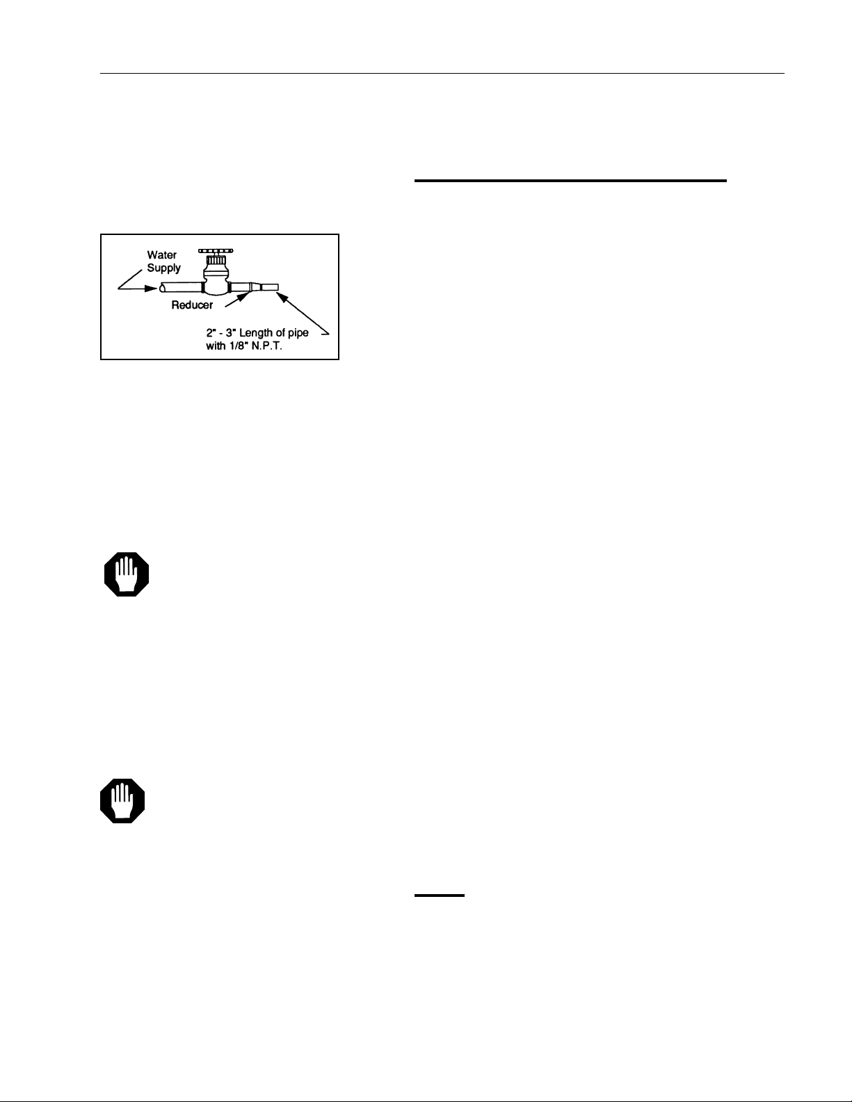
OPTION #1
A single, untreated cold water supply. The supply
must be capable of providing a minimum of 16
gallons per hour at a pressure of 20-100 psi and
be located within 4 feet of the water still. You must
provide a shut-off valve and reducer as shown in
Figure 3. With Option #1, approximately 16
gallons of untreated water will be used per hour in
the cooling section of the still, 2 gallons of this
water will be used as boiler feed. Water
connections are discussed on pages 12-14.
OPTION #2
An untreated cold water supply plus a source of
RO, demineralized or previously distilled water.
The untreated supply must be capable of
providing a minimum of 16 gallons per hour at a
pressure of 20-100 psi and be located within 4
feet of the water still. The treated supply must be
capable of providing 2 gallons per hour and be
located within 4 feet of the water still. You must
provide a shut-off valve and reducer at each water
supply (see Figure 3). In addition you will require
the optional double solenoid valve kit (Catalog No.
440236). With Option #2, approximately 16
gallons of untreated water will be used each hour
for cooling. The second (treated) water supply of
2 gallons per hour will be used as boiler feed.
Water connections are discussed on pages 12-14.
Drain
An open or atmospherically vented drain located
lower than the still is necessary to allow for gravity
flow. Barnstead supplies a 5 foot length of 1/2"
I.D. vinyl tubing for the drain. Additional tubing
may be purchased from your laboratory dealer.
Caution
Never use 208V heaters on
voltage higher than 208 volts as
premature heater failure will
occur.
Caution
Do not use NaCI regenerated
water softeners to supply boiler
feed as alkali attack will shorten
heater life.
Shut-off Valve
GENERAL INFORMATION

8
Unpacking
1. Remove the parts box and the still from
the shipping carton and place on a work-
bench.
2. Remove the two (2) shipping screws
located on the upper back of the unit and
discard. Turn the two (2) cover fasteners
located on the lower front of the unit 1/4
turn counterclockwise, and lift the cover
out and up to remove. Set the cover aside.
3. Check the glassware inside the main
cabinet for damage. Check the parts in the
accessory box for damage. Identify any
broken or damaged parts and report them
to your dealer immediately.
Refer to Figure 4 for the following steps:
4. Using diagonal cutting pliers, cut and
remove the five (5) plastic shipping ties.
The shipping tie locations are: Two (2) on
the condenser (B), two (2) on the boiler (P)
and one (1) on the trap (U) .
5. Using a 7/16" wrench, loosen the nut (all
the way) on coupling (C) While holding
onto the condenser, remove springs (Y).
Carefully remove the condenser from the
coupling and the cabinet.
6. Remove the tape from the condenser
outlets. Allow the salt used as packing to
flow into the plastic bag around the con-
denser. Discard the bag and the salt.
Rinse the remaining salt residue from the
condenser.
Unpacking

9
Assembly
Tools required for assembly: 7/16"
open end
wrench, diagonal cutting pliers, common
screwdriver.
1. Reinstall the condenser (B) into the
coupling (C) and clamp the condenser
in place with springs (Y).
2. Tighten coupling (C) using a 7/16"
wrench. The coupling should be just tight
enough to prevent rotation with moder-
ate hand pressure.
3. Check the orientation of trap (U). If it is
not level or tilted back toward the boiler
as shown in Figure 4, move the con-
denser (B) up in its bracket. This will tilt
the trap as shown in Figure 4.
4. In the following steps, use warm water
on the connections for ease of assembly.
A. Connect tube (V) to upper the right
condenser tubulation using Teflon®
connector (W).
B. Connect the vinyl tubing from the flow-
meter to the lower right tubulation of the
condenser.
5. Remove the packing material and rotate
tube (Q) into the constant level chamber
of boiler (P) as shown in Figure 4.
6. Unpack the Vycor®immersion heaters
(R) and check the voltage rating on the
top cap. It should agree with the voltage
of your power supply. If it does not,
contact your dealer and order the correct
heater.
Caution
Do not remove the Teflon®
sleeve covering the molded
rubber sleeve on the heater
element.
Assembly

10
7. Insert the immersion heaters into the top
openings of boiler (P) as shown in Figure
4.
8. Thread the heater plugs and cords through
the large hole above the boiler (P), then
back through the hole below the control
box (O). Plug the heater plugs into the
receptacles on the bottom of the control
box. The plug is a twist-lock type and
requires a 1/4 clockwise turn to lock in
place.
9. Route the water supply and the drain
tubing through the side of the cabinet.
Pretreated Boiler Feed
When a supply of distilled, deionized or reverse
osmosis water is to be used as boiler feed, revise
the still connections as follows:
1. Remove boiler fill tubes (V) and (Q) and
set aside.
2. Locate the 3/8" I.D. x 44" long vinyl tubing
and one barbed tee (1/2 x 1/2 x 3/8) in the
parts box.
3. Install one end of the vinyl tubing to the top
right tubulation on the condenser (B) and
route the other end through the cabinet
and down the back as shown in Figure 5.
4. Cut the 1/2" I.D. vinyl drain tubing and
install the barbed tee fitting. Connect 3/8"
I.D. vinyl tubing from the condenser to the
barbed tee . Push the vinyl tubing all the
way onto the tee to assure a leak free seal.
Figure 4
Note
Refer to the Pretreated Boiler
Feed section if you will be
using a source of pretreated
water as boiler feed or to the
3 1/2 Gallon Storage Bottle
section if the optional 3 1/2
gallon storage bottle is being
installed. If neither applies,
move assembled still to its final
location. See pg. 14 for layout
recommendations, and pgs. 12-
14 for plumbing details.
ASSEMBLY

11
5. If the 3 1/2 gal. storage bottle is not
being installed, move the still to its final
location. See page 12 for layout recom-
mendations and pages 10-12 for final
plumbing details.
3 1/2 Gallon Storage Bottle
To install the optional 3 1/2 gallon storage bottle
inside the MEGA-PURE®6A Water Still cabinet,
first locate the following parts:
• Bottle dust cover (F)
• Product delivery tube (E)
• Thomas clamp (D)
• 20" length of 1/2" vinyl tubing
• Plastic tee (1/2 X 1/2 X 1/2)
1. Place the bottle dust cover on the 3 1/2
gallon bottle and route the product
delivery tube through the hole in the
cover. Place this assembly inside the still
cabinet below the condenser (B) and
connect the product delivery tube to the
condenser with clamp (D).
2. Locate the plastic tee (1/2 x 1/2 X 1/2)
and the 20" length of 1/2" vinyl tubing in
the parts box. Connect to the bottle
overflow tubulation and drain as shown
in Figure 6.
3. Move the still to its final location. See
page 14 for layout recommendations
and pages 12-14 for final plumbing
details.
Figure 5
Figure 6
ASSEMBLY

12
Automatic Collection System
Before connecting your MEGA-PURE®6A Water
Still to the Barnstead Automatic Collection System
move the still to its final location.
Locate ACS tube (Z) and Thomas clamp (D) in the
parts box. Assemble to the tubing from the
collection system as shown in Figure 10.
Plug the input jack from the ACS into the ACS
receptacle on the bottom of the still control box (O).
See pages 12-14 for final plumbing details.
Plumbing Details
Tap water feed only - Figure 7
1. Thread the solenoid valve onto the cus-
tomer supplied shut-off, “in’ side towards
shut-off.
2. Install 1/4" O.D. tubing and supplied fitting
to “out” side of solenoid valve.
3. Route 1/2" I.D. vinyl tubing to an atmo-
spherically vented drain.
4. Plug the solenoid valve power cord (not
shown) into the receptacle in the control
box (O).
Figure 7
Tap Water Feed
Plumbing Details

13
Tap water/Demineralizer - Figure 8
(Must have the optional still adapter kit: catalog
no. 440376).
1. Thread the solenoid valve (“in” side
towards shut-off) onto the customer
supplied shut-off.
2. Install 1/4" O.D. tubing and the sup-
plied fitting to the “out” side of the
solenoid valve.
3. Cut the 1/4" O.D. tubing from the last
step at a convenient point and install
the tee from the still adapter kit.
4. Connect the 1/4" O.D. tubing from the
demineralizer to the tee.
5. Locate the boiler fill tube (Q). Connect
3/8" I.D. vinyl tubing from the deminer-
alizer output to the end of the boiler fill
tube. Route as shown and install clip
(T) to support.
6. Route the 1/2" I.D. vinyl tubing to an
atmospherically vented drain.
7. Plug the solenoid valve power cord
(not shown) into the receptacle in the
control box (O).
8. Plug the still adapter kit cable into the
receptacle located on the right side of
the demineralizer and the receptacle
in the control box (O).
Figure 8
Tap Water Demineralizer
PLUMBING DETAILS

14
Tap water/In-House Treated Water - Fig. 9
(Must have the optional double solenoid valves:
Catalog No. 440236)
1. Thread the solenoid valves (“in” side towards
shut-off) onto the customer supplied shut-
offs.
2. Install 1/4" O.D. tubing and the supplied
fitting to the “out” side of the solenoid on the
tap water.
3. Connect the fitting and 3/8" I.D. vinyl tubing
from the double solenoid valve kit to the “out”
side of the treated water supply.
4. Locate boiler fill tube (Q). Connect 3/8" I.D.
tubing from the treated water supply solenoid
to the end of the boiler fill tube. Route as
shown and install clip (T) to support.
5. Route 1/2" I.D. vinyl tubing to an
atmospherically vented drain.
6. Plug the solenoid valve power cord (not
shown) into the receptacle in the control
box (O).
Installation
Location of Unit
Space allotment for a still should include a 6"
clearance at the sides and top to allow for cover
removal and air circulation.
Do not mount your MEGA-
PURE®6A Water Still directly
over equipment that requires
electrical service. Routine
maintenance of this unit may
involve water spillage and
subsequent electrical shock
hazard if improperly located.
Warning
Figure 9
Tap Water/In-House Treated Water
Installation

15
Wall mounting
The MEGA-PURE®6A Water Still has slotted
holes for wall mounting. To support the weight of
this unit, use 1/4" x 1 1/4" lag bolts for mounting.
An optional wall mounting bracket is available for
the Automatic Collection System. Barnstead
demineralizers have slotted holes for wall
mounting. Demineralizer location is not critical,
though it should be close enough to the still to
make all necessary connections and should not
be mounted over electrical equipment to avoid
shock hazard (see warning above).
Bench mounting
No special consideration for a “still only” setup.
When used with the ACS, the MEGA-PURE®6A
Water Still must be placed on a 12" platform to
allow for gravity feed of distilled water to the ACS.
Caution
Replace front protective cover
before proceeding.
Wall composition and
construction, as well as fastener
type, must be considered when
mounting this unit. The mounting
surface and fasteners selected
must be capable of supporting a
minimum of 110 lbs.; inadequate
support and/or fasteners may
result in damage to mounting
surface and/or equipment. If you
are unsure of mounting surface
composition, condition and
construction, or correct fasteners,
consult your building
maintenance group or contractor.
Warning
Figure 10
INSTALLATION

16
Operation
Refer to Figure 11:
1. Close the drain stopcock (K) on the bottom
of the boiler (P).
2. Open the valve at the tap water source and
the treated water source if so installed.
3. Switch on the main power breaker on the
control at the customer power source.
4. Push “Water” switch on control box (O)
and allow boiler to fill. Set Flowmeter (L) to
approximately 15 Gal/Hr.
5. Push “OPERATE” switch. Light will light
and heaters will come on.
6. Allow the still to operate for 15-20 minutes.
For distillate at maximum purity, set the
flowmeter (L) at 11-12 GPH. For maximum
volume of distillate, increase flow at flow-
meter (L) to the point where only a slight
wisp of steam is visible at the condenser
vent (A).
7. Your MEGA-PURE®6A Water Still should
now be operational. Run the still for 4-5
hours to allow it to cleanse itself before
collecting water for use. (Dispose of the
water produced during the 4-5 hour cleans-
ing period.)
8. To shut your water still off, push the OFF
switch. This will shut the water supply and
the heaters off.
Pretreated feedwater-flow rate
to be adjusted so as to “just
maintain a full boiler”. Too fast
a flowwater will exhaust
pretreatment cartridges
prematurely.
Note
Operation
Warning
Do not use in the presence of
flammable or combustible
materials; fire or explosion may
result. This device contains
components which may ignite
such materials. Use this device
with water feed only. Failure to
comply with the above could
result in explosion and personal
injury. To avoid electrical shock,
always use a properly grounded
electrical outlet of correct voltage
and current handling capacity.
Ensure that the equipment is
connected to electrical service
according to local and national
standards. Failure to properly
connect may create a fire or
shock hazard.
Avoid Contact. Hot water and
steam heat the glass portions of
the still to dangerous
temperatures during operation.
Hot Surface

17
If any difficulties are encountered in operating this
water still, check all operating and assembly
steps to be sure the still was assembled and is
being operated correctly. If the difficulty still
exists, consult the Troubleshooting section of
this manual.
High Temperature Cut-off Switch
Your MEGA-PURE®6A Water Still is protected
against overheating by dual thermal switches
located in the brackets at the sides of the boiler.
Should the boiler overheat, a switch will open
causing the heaters and water supply to shut-off.
When the boiler cools (5-15 minutes), the switch
will reset automatically, but the still will have to be
restarted by the operator. When unit has cooled,
press the “WATER” and “OPERATE” switches to
restore normal operation. Check the boiler
occasionally for proper water level.
OPERATION
Caution
Do not use the flowmeter to turn
the water off.
Caution
Always allow the unit to cool
completely before resuming op-
eration. Cool water on hot glass
could cause boiler damage.
Note
Under most feedwater
conditions, the 11-12 GPH
flow rate will provide
greater than 60°C at the
condenser vent. Very cold
feedwater may require
slightly less than 11-12
GPH to maintain vent
temperature above 60°C.
To optimize product water
purity, use thermometer to
verify vent temperature to
> 60°C.
18
Maintenance and Servicing
Cleaning
For top performance and efficiency, the
MEGA-PURE® 6A Water Still should be kept
clean and free of scale. It is recommended that
the boiler be drained and refilled with fresh water
daily to flush the boiler of the concentration of
contaminants from the previous day’s run.
When using untreated boiler feed, cleaning is
recommended after every 15-20 hours of
operation. The unit should be cleaned with a
hydrochloric acid solution. This is done as follows:
1. Push the unit’s “OFF” switch.
2. Disconnect the output tubing at the
condenser (B) from the collection vessel
and temporarily place a beaker under
the condenser outlet.
3. Drain the boiler 2/3 by opening the
stopcock (K). Close the stopcock (K)
after the boiler has drained.
4. Use the spare pinch clamp from the
parts box to shut-off the overflow tube
from the constant level chamber (N) as
close as possible to the overflow stem.
5. Carefully pour approximately 400 ml. of
10% hydrochloric acid solution into the
top of the constant level chamber (N).
May need to add water to boiler to bring
solution level up to scale level.
6. Wait approximately 10 minutes or until
the residue disappears. If additional
cleaning is required, drain the boiler
Warning
Ensure adequate ventilation
when using chemicals for clean-
ing. Wear eye and hand protec-
tion when using acid for clean-
ing, as acid spattering may
occur.
Warning
To avoid electrical shock, al-
ways disconnect from power
supply before maintenance and
servicing. Refer servicing to
qualified personnel. For contin-
ued protection against possible
fire hazard, replace fuses only
with the same type and rating of
fuse.
Maintenance and Servicing

19
down 1 inch and turn the unit on for a
few minutes until the residue disappears.
Do not boil. Turn still off. If scale re-
mains that the 10% hydrochloric solution
will not remove, rinse boiler three times
with feedwater (fill and drain). Add 400
ml of 6% NaOH to boiler and let stand
for 30 minutes. Flush boiler several
times after draining.
7. Carefully drain the unit, remove the
clamp from the overflow tube and refill
with fresh water. Drain the boiler, refill
with fresh water and operate for 30
minutes. Reconnect the tubing from the
collection vessel to the condenser (B).
MAINTENANCE AND SERVICING

20
Troubleshooting
General
melborPsesuaCnoituloS
skaeL
enosikaelnommoctsomehT
niardlynivehtnignirrucco
sesuacretawtoH.gnibut
taesoolgnillupdnagninetfos
.srotcennocdebrabcitsalpeht
gnibutlynivfosnuR
otdetroppusebdluohs
ehtnollupehtecuder
.srotcennoccitsalp
ebyamspmalcllamS
ehtdlohylmrifotdesu
ehtotgnibutlyniv
.srotcennoccitsalp
gnilioBhguoR
fotluserehtsigniliobhguoR
hsinifettamehtotkcattailakla
tsomehT.sretaehehtno
retawgnisusiesuacnommoc
ICaNhtiwdetaerterp
.srenetfosretawdetareneger
dnaretaehevomeR
ecafrusnehguorylthgil
tirg051htiw
.repapdnas
pu-dliuBelacS
ehtnielacsetihw-hsinworbA
reliobehttahtsetacidnireliob
.gninaelcseriuqer
repreliobnaelC
.snoitcurtsnigninaelc
ebtondluohselacS
etalumuccaotdewolla
ebyamsretaehsa
.degamad
eruliaFretaeH
®rocyVnoefiltrohS
yllausunacsretaehnoisremmi
retawfoesuotdetubirttaeb
ICaNhtiwdetaerterp
rosrenetfosretawdetareneger
.pu-dliubelacsevissecxe
asadesuretawdenetfoS
asesuacdeefreliob
snoimuidosfonoitartnecnoc
ehtfokcattaenilakladna
gniliobhguoR.ssalg®rocyV
fonoitacidnitsrifehteblliw
eht,eruliaftA.kcattaenilakla
dnaelohnipyllausulliwsretaeh
ehttuotrohslliwgniretneretaw
.tnemele
nehwruccolliwpu-dliubelacS
gniebtonsideefreliob
.dezinoied
tsumretawdenetfosfI
efilretaeh,desueb
degnolorpebnac
gniniardybtahwemos
.yadyrevereliob
llitsehtgnisunehW
,rezinoiedehttuohtiw
ebtsumpu-dliubelacs
yreveretfadevomer
fosruoh02-51
eeS(.noitarepo
.)snoitcurtsnIgninaelC
lliwosodoteruliaF
dliubotsretaehesuac
dnayllanretnitaehpu
ssalgesuacroliaf
.eruliafepolevne
tamaetS
tneVresnednoC
tagnitixemaetsfopsiwthgilsA
.lamronsitnevresnednoceht
oslaeramaetsehtnisesaG
.devomergnieb
evissecxenasierehtfI
maetsfotnuoma
resnednocehtgnivael
ehtesaercni,tnev
etarwolfretawgnilooc
.)L(retemwolfta
This manual suits for next models
1
Table of contents


