Woson DRINK10 User manual

WOSON Medical System
Technical
Publications
ASS0010
REV-A
DRINK10 Water Distiller
Operation Manual
Operation Documentation
Copyright © 2011 By Ningbo Woson Medical Instrument Co., Ltd..
Ningbo Woson Medical Instrument Co., Ltd
Address: No.19, Lane 346, Changxing Road, Jiangbei
District, Ningbo 315032, China
Tel: 86-574-83022668
Fax:86-574-87639376
Website:http://www.woson.com.cn

DRINK10 Distiller Operation Manual
REV-A Page 1 of 26
Regulatory Requirement
This product complies with regulatory requirements of the following European
Directive 93/42/EEC concerning medical devices.
Revision History
Rev
Issue Date
Reason For Change
Rev-A
2011.01.28
First Issue
Please verify that you are using the latest revision of this document. Information pertaining to
this document is maintained on manufactory. If you need to know the latest revision, please
contact your distributor, sales representative, or our service dept.
Regulatory Requirements
Conformance Standards
The content of this instruction is fit for water distiller.
Above water distiller in accordance with the requirements of 93/42/EEC
EN 61010-1:2001
Certifications
Manufacturer is ISO 9001 and ISO 13485 certified.

DRINK10 Distiller Operation Manual
REV-A Page 2 of 26
Content
Regulatory Requirement ...........................................................................................................................1
Revision History.......................................................................................................................................1
Regulatory Requirements .........................................................................................................................1
Content .....................................................................................................................................................2
Chapter 1 Introduction .............................................................................................................................3
1.1 Attention..............................................................................................................................3
1.2 Application Range...............................................................................................................3
1.3 Method ................................................................................................................................3
1.4 Contradictions .....................................................................................................................3
Chapter 2 Safety ....................................................................................................................................... 4
2.1 Symbol Explanation............................................................................................................4
2.2 General Safety Recommendations ......................................................................................4
2.3 Safety Parts .........................................................................................................................5
2.4 Operating Risk ....................................................................................................................5
Chapter 3 Receiving and Installation .......................................................................................................6
3.1 Checking the Package .........................................................................................................6
3.2 Open the Accessories List ...................................................................................................6
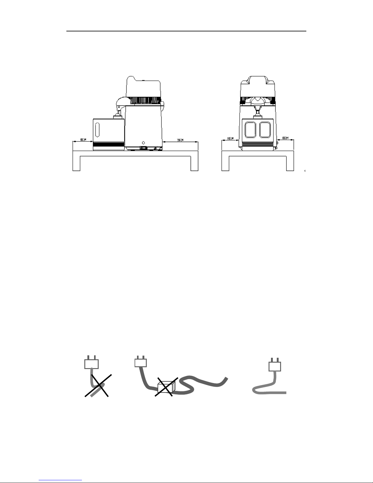
3.3 Working Environment .........................................................................................................7
3.4 Installation...........................................................................................................................7
3.5 Power Connector.................................................................................................................7
Chapter 4 Product Description and Specification....................................................................................8
4.1 Front View...........................................................................................................................8
4.2 Lateral View ........................................................................................................................8
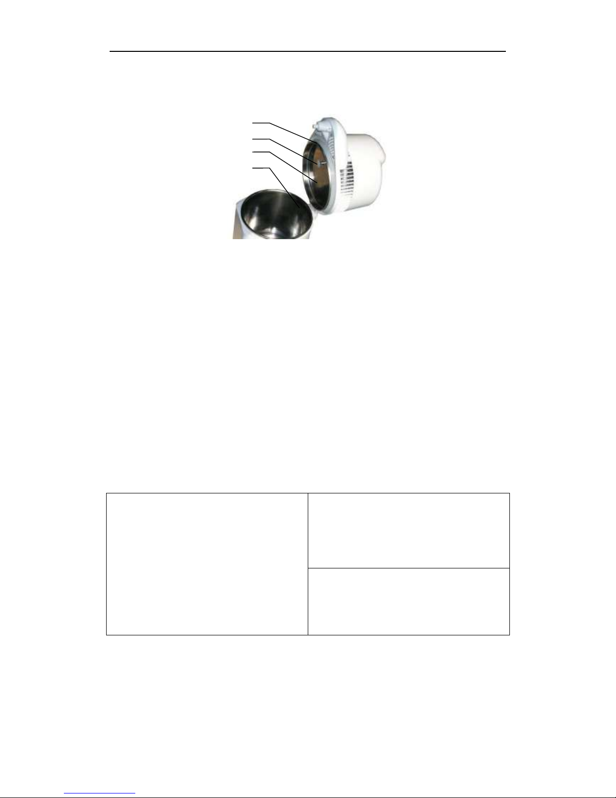
4.3 Open View...........................................................................................................................9
4.3 Size and Capacity................................................................................................................9
4.5 Specification........................................................................................................................9
Chapter 5 Operation Process .................................................................................................................10
5.1 Setting ...............................................................................................................................10
5.2 Water-adding .....................................................................................................................10
5.3 Power Connector...............................................................................................................10
5.4 Starting ..............................................................................................................................10
5.5 Ending ...............................................................................................................................10
5.6 Power Off.......................................................................................................................... 11
Chapter 6 Maintenance .......................................................................................................................... 11
6.1 Maintenance Schedule Chart............................................................................................. 11
6.2 Daily Maintenance ............................................................................................................11
6.3 Monthly Maintenance .......................................................................................................12
6.4 Quarter Maintenance.........................................................................................................12
Chapter 7 Troubleshooting ..................................................................................................................... 13
Chapter 8 Transport and Storage ........................................................................................................... 14
8.1 Preparing for Transport and Storage .................................................................................14
8.2 Transport and Storage Conditions .....................................................................................14
8.3 Package .............................................................................................................................14
Appendix 1 Electrical Connection Diagram........................................................................................15

DRINK10 Distiller Operation Manual
REV-A Page 3 of 26
Chapter 1 Introduction
1.1 Attention
This manual contains necessary and sufficient information to operate the system safely,
like optimal use, a safe and reliable operation, regular and correct servicing
requirements.
Read and understand all instructions in this manual before attempting to use the product.
Keep this manual with the equipment at all times. Periodically review the procedures for
operation and safety precautions.
1.2 Application Range
The medical distiller is designed by our company, which is for the places that needs
High-purity water, such as clinic, Beauty Studio, hospital, laboratory.
Operated by adult. Considering Ergonomic, it outstands on convenient using and safety,
and continually, it can produce pure water 1L per hour in average.
1.3 Method
The pure water producing method is to transform liquid water into gaseous water by heating,
then to achieve pure water(distilled water) through cooling.
1.4 Contradictions
No Contradictions

DRINK10 Distiller Operation Manual
REV-A Page 4 of 26
Chapter 2 Safety
2.1 Symbol Explanation
Device Icon Description
“ATTENTION” – Refer to this Operation Manual” is intended to alert the
user to refer to the operation manual or other instructions when
complete information cannot be provided on the label.
“Protective Earth” - Indicates the protective earth (grounding) terminal.
Operating Tips
Note
Indicates that concerning information which easier or helpful in operation
CAUTION
Indicates that a potential hazard may exist which through inappropriate
conditions or actions will or can cause:
• Minor injury
• Property damage.
• Damage to machine
WARNING
Indicates that a specific hazard is known to exist which through inappropriate
conditions or actions may cause:
• Severe personal injury
• Substantial property damage
• Substantial damage to machine
NOTE: Indicates precautions or recommendations that should be used in the operation.
2.2 General Safety Recommendations
The user is responsible for operation and servicing the machine in accordance with the
instructions listed in this manual.
Uncover the top air outlet while using.
Keep body shell dry(especially Outlet section for avoiding short current or electric shock).
As the cover connects tightly with the body, please press the body with one hand, and pull
the cover upward with another.
For safety, please protect the cover after open it, for it can close automatically under
external pressure.

DRINK10 Distiller Operation Manual
REV-A Page 5 of 26
For avoiding leaking, please press the cover, and make sure the cover connects with
the body completely.
Do not drink pure water in the first bucket. Perhaps, it has the impurity of producing
process or packaging process.
Do not open the cover while working, because you may hurt by water vapor.
Minors are forbidden using!
2.3 Safety Parts
Heating Protect
Part Name
Function
KSD301
Temperature Controller
170 degree C automatic reset. Protecting Electric heating rings
from damage of high temperature.
KSD301
Temperature Controller
115 Degree C manual reset. Avoiding auto-heating after water
boiled while power on.
KSD301
Temperature Controller
80 degree C automatic reset. For energy-saving and safety,
the cooling fan's running is controlled by chamber temperature.
Electric Protection
Part Name
Function
Fuse
Clear the circuit when short circuit or over current.
Rocker Switch
(Power Switch)
Convenient to start or end the distiller at any time
CAUTION
MANUFACTURER IS NOT HELD RESPONSIBLE FOR ANY ARBITRARY
DISASSEMBLY, AMENDMENT WITH THE UNIT, BY UNAUTHORIZED
PERSON OR UNPROFESSIONAL TECHNICIAN
2.4 Operating Risk
For avoiding risk, please be cautious at operation.
Operating Risk
For safety, please protect the cover after open it, for it can close automatically under external
pressure.
Burn hazard
Do not open the cover while working, because you may burned by water vapour.
The risk of contamination
For avoiding leaving contamination in chamber, please clean chamber as soon as possible.

DRINK10 Distiller Operation Manual
REV-A Page 6 of 26
Chapter 3 Receiving and Installation
3.1 Checking the Package
Please check the package carefully when you receive the production, for the production can
be damaged by package disrepair anywhere.
Front View
Lateral View
Model
DRINK10
Packing Size
mm
26 X 26 X 42 CM
Packing Weight
Kg
4.4 KG
3.2 Open the Accessories List
open the package, and count the accessories according to the list:
NO
Part Name
Quantity
1
Faucet
1
2
Two Sizes of Filter
2 of Each
3
Active Carbon
1
4
Abluent
1
5
Rubber Plug in Vent Port
1
6
10A Fuse
1
7
Distilled Water Bottle
1
8
Bottle Cover
1
9
Diversion port
1
10
Operation Manual
1
11
Power Cable
1
N.W.: KGS
G.W.: KGS
SIZE: 26×26 ×42
CM
WAGER DISTILLER

DRINK10 Distiller Operation Manual
REV-A Page 7 of 26
3.3 Working Environment
Distiller installation should be left at least 10cm all around, and 20cm to the top.
Advise installing in an environment with good condition of ventilation.
Ambient temperature:0-30℃.
Relative humidity: ≤80%
Air-pressure: 860Hpa~1060Hpa
Earthing
3.4 Installation
Set the distiller on a stable surface, and keep at least 10cm from graphic edge.
For safety, please remove all stuff from distiller.
For convenient operation, please remove all stuff in front of distiller.
Do not set bottle with rusty liquid around distiller, for eliminating potential hazard while
Thermal distillation.
3.5 Power Connector
Check the nameplate under distiller bottom whether it corresponds relevant supply
voltage or not.
The provided cable location is in the bottom side.
Caution
Do not split or fold power cord for avoiding power cord damage!
Do not put any heavy stuff on the power cord for avoiding power cord
damage!
Do not use other power cord for avoiding Electrical components damage!
Do not use lengthened power cord for avoiding current leakage!
Wrong
Wrong
Right

DRINK10 Distiller Operation Manual
REV-A Page 8 of 26
Chapter 4 Product Description and
Specification
4.1 Front View
4.2 Lateral View
Name
Description
7
Power Outlet
Connect the power
8
Fuse Holder
The place of installing fuse
9
Connecting Joint
Connection with the lower body upper body joint
Name
Description
1
Filter Tip
Collecting and filtering distilled water
2
Cover
The upper part of distiller, including Condensation cooling
system
3
Body
The main part of distiller, including chamber and heating
system
4
Temperature Protection
Switch
Temperature protection of the reset switch
5
Power Switch
In charge of power,indicator light in power switch on
means the distiller is working。
6
Collecting Bucket
The vessel of collecting distilled water
2
5
4
6
1
3
7
8
9

DRINK10 Distiller Operation Manual
REV-A Page 9 of 26
4.3 Open View
Name
Description
10
Obturating Ring
To airproof the cover and the body
11
Rubber Plug in Vent
Port
To prevent water into vent port which may influence the purity
of distilled water
12
Cover
The sainless steel cover of chamber to keep heat and
13
Chamber
The stainless steel chamber to heat water
4.3 Size and Capacity
Size
DRINK10
External Size
225×270×370mm
Packing Size
260×260×420mm
Full Level Capacity
Φ180×142
4.5 Specification
Essential Parameter
Rated Volyage: a.c.220V-240V,50/60Hz
Rated Power: 750VA
Fuse: 250v T10A
Operating Temperature: 5~40℃
Noise:< 50db
Speed:1.2L/H
Water Rate:≥96%
Chamber
Material: Stainless Steel304
Maxium Capacity:4L
The Highest Temperature: 120 ℃
Volume Cavity Size:φ180*185
Temperature Safety Protection:
Cavity temperature protection:115 ℃
Temperature of the heating element
protection:170 ℃
10
11
12
13

DRINK10 Distiller Operation Manual
REV-A Page 10 of 26
Chapter 5 Operation Process
5.1 Setting
Open the packing chest. Take the distiller out of the chest. Then take the storage bucket
out of the distiller. Set the distiller on a stable surface in terms of picture 1.
5.2 Water-adding
Open the cover (As picture 2). Pour proper volume of water into the chamber within the
highest waterline. (Remark:As the cover connects tightly with the body, please press the
body with one hand, and pull the cover upward with another.)
5.3 Power Connector
Set the storage bucket stably according to picture 1, insert the one end of power cord into
the body, and another into correct electric outlet.
5.4 Starting
Open the power switch (If the power switch off, press the heating button), If the indicator
light in power switch on, it means start to heating. After a period of time, the cooling fan will
run automatically for distilling.
It takes about 3.5 hours to distill 4L water, and the first pure drop will appear after half an
hour, according to local temperature.
5.5 Ending
When distilling finished, the heating system will stop automatically, and indicator light will
be off. However, the cooling fan will keep running until the chamber temperature drops
below 70 degree C.
CAUTION
Heating button is in charge of heating process start. The heating process will
stop automatically when there is no water or no water for distilling. (When
heating, indicator light in power switch on; stopping, off). Power switch
controls both of heating and cooling fan’s running.
CAUTION
For filtering, the distiller is furnished with active carbon. In accordance with
demand, you can put the active carbon into the faucet, and cover with filter
cap. Remark: replace the active carbon regularly.
ATTENTION
As the cover connects tightly with the body, please hold the body with one
hand, and pull the cover upward with another.
WARNING
FOR AVOIDING BEING SCALDED, DO NOT OPEN THE COVER WHILE
WORKING.

DRINK10 Distiller Operation Manual
REV-A Page 11 of 26
CAUTION
As upper cover is heavy, do not open and erect it while using.
5.6 Power Off
Please Close the power switch when no longer in use.
Please pull the end of power cord out of electric outlet when no longer in use of distiller.
Chapter 6 Maintenance
6.1 Maintenance Schedule Chart
Maintenance Required
Person Responsible
Daily
Clean Body
User
Clean Chamber
User
Clean Storage Bucket
User
One Month
Clean Chamber with Abluent
User
One Quarter
Filter Tip Replacement
User
6.2 Daily Maintenance
Clean Body and Chamber
Please clean and drain the chamber and body with soft towel after using.
WARNING
DO NOT CLEAN DOOR OR ASSEMBLE CHAMBER WITH METALLIC
BRUSH, STEEL WOOL OR PRODUCTS CONTAINING CHLORIDE. TO
AVOID SCALD, PLEASE MAKE SURE DISTILLER IS COOLED DOWN
BEFORE CLEANING.
Cleaning Storage Bucket
Storage Bucket can be disinfected and cleaned with warm (hot) water, and it will not be
out of shape by hot water.

DRINK10 Distiller Operation Manual
REV-A Page 12 of 26
6.3 Monthly Maintenance
Cleaning Chamber with Abluent
The internal of stainless steel tank need to be washed with clean water in order to remove the
distillation residual precipitation and impurities. And please clean the stainless steel tank per
month (or depend on the quantity of dirt within the slot), with the detergent which we
recommend to you ,the procedure as follow:
A. Add enough (hot) water into tank till cover dirt.
B. Put one or four (depends on quantity of dirt) spoon of detergent into tank.
C. Heat water with lid opened
D. Pour out water after 30 minutes, and then wash the tank with clean water.
E. If cannot remove all dirt, please repeat process.
F. Residual dirt will not affect health, please feel free to use the machine.
6.4 Quarter Maintenance
For guarantee the purity and quality of distilled water, you need to replace the faucet regularly.
The step as follows:
A. Push the left or right side of faucet, and then pull it, you can take it off.
B. According to the way of taking, you can put it on in an opposite way.
C. Repeat those steps when it needs to replace.
ATTENTION
PLEASE INSERT THE ACTIVE CARBON INTO FILTER BEFORE INSTALL
FAUCET WHEN YOU NEED ACTIVE CARBON FOR FILTERING.

DRINK10 Distiller Operation Manual
REV-A Page 13 of 26
Chapter 7 Troubleshooting
No.
Fault
Description
Solutions
1
No distilled water
out
Not heated (indicator dawn), heating
switch is not open
Press heating switches (this switch
design is tight, please skill protect
living organism, another hand
pressure heating switches)
Not heated (indicator dawn), fuse
disconnect
Replace the fuse (10A)
Not heated (indicator dawn), socket
not connected
Check socket and connect it
Tank without water injection
Add water into tank
Master switch is not opened
Open master switch
2
Water production
can not reach the
standard.
(Standard is more
than 96%)
Rubber seal ring between lid and
tank is not tight.
Replace the rubber seal ring.
Lid is not closed tightly, air leaks.
Close tightly
Dirt cover on condense pipe wall
thickly, affects the condensing effect
(water temperature higher than 50
degree)
Maintenance by professionals
3
Water leakage
Cover checkpoint. missing tight,
steam leakage, condensing into
water, and outflow.
Please check the lid and tight it.
Distilled water outflow form nozzle is
over-heat, steam around nozzle
condensing into water.
Environmental temperature higher
than 40 degrees, there will be few
outflows. The proper temperature is
lower than 30 degrees.
Dirt on condense pipe wall is thick,
affects the condensing effect, need
to be maintained by professional
Fan does not work. maintained by
professional
Rubber seal ring between lid and
tank is not tight. Air leakage and
condensing into water, and outflow.
Replace the rubber seal ring
Note: in case the related issues not mentioned above, please contact with us or outlets to solve.

DRINK10 Distiller Operation Manual
REV-A Page 14 of 26
Chapter 8 Transport and Storage
8.1 Preparing for Transport and Storage
Power off, pull the plug out. Make sure the machine has been cool. Then drain the body,
chamber with towel.
8.2 Transport and Storage Conditions
Temperature: -5 ℃~ +55℃
Humidity Level: ≤85%
Air-pressure : 500HPa~1060HPa
8.3 Package
For protecting, transporting and marketing in transportation, the package should be packed
firmly and prevents production from pressing.

DRINK10 Distiller Operation Manual
REV-A Page 15 of 26
Appendix 1 Electrical Connection Diagram
Fan Motor
Heating
Ring
Switch
Fuse
~230
115°Temperature
Protector
170°Temperature
Protector
M
Lamp
80°Temperature
Protector
Table of contents