Barreto 712MT User manual

712MT OWNER’S MANUAL REVISED 3/4/22 Page 1 of 15
THE
MODEL 712MT
HYDRAULIC MICRO TRENCHER
OWNER’S MANUAL
CONGRATULATIONS!
You are now the proud owner of a BARRETO trencher. The OPERATOR’S MANUAL is attached
to the machine. Please study both this manual and the operator’s manual to become familiar with the
trencher, its characteristics and its method of operation. Pay particular attention to the safety and
operating instructions to prevent personal injury or equipment damage.
If you have any questions or need any replacement parts in the future, please contact us at your
convenience. Our toll-free phone number, fax and email are listed below.
Thank you for your patronage and confidence in BARRETO equipment.
Barreto Manufacturing, Inc.
Innovative Equipment Engineered to Last
66498 Highway 203
La Grande, OR 97850
1-800-525-7348
1-541-963-6755 Fax
E-Mail: [email protected]
Web Site: http://www.barretomfg.com
Machine Identification Record
Machine model number ________________________
Machine serial number ________________________
Engine manufacturer ________________________
Engine model number ________________________
Engine serial number ________________________

712MT OWNER’S MANUAL REVISED 3/4/22 Page 2 of 15
TABLE OF CONTENTS
Assembly Instructions..................................................................................................................3
Service Information......................................................................................................................3
Hour Meter ...................................................................................................................................4
Intended Use.................................................................................................................................5
Lubrication Requirements............................................................................................................5
Chain Installation..........................................................................................................................6
Operator Training.........................................................................................................................6
Warranty of Barreto Equipment...................................................................................................7
Maintenance Preparation..............................................................................................................7
Routine Maintenance....................................................................................................................8
Electrical Schematic - Honda GX200 ........................................................................................99
Hydraulic Schematic ................................................................................................................100
Wheel Drive Unloader Valve...................................................................................................111
Troubleshooting Guide.............................................................................................................122
Specifications ...........................................................................................................................144
Index.........................................................................................................................................155

712MT OWNER’S MANUAL REVISED 3/4/22 Page 3 of 15
TRENCHER ASSEMBLY INSTRUCTIONS
Upon delivery, check for freight damage and/or missing items. Report any damage immediately to the
carrier and Barreto Manufacturing. Remove trencher from shipping crate.
When documentation refers to “right side” or “left side”, it is relative to the operator’s position with
both hands on the handlebars.
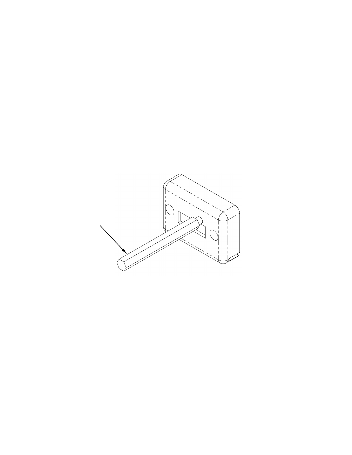
Install cushion pad, boom cushion and boom.
CAUTION!! The boom is heavy. You may want help to lift it into place (see exploded view
drawing 00476). Push boom onto the boom mount as far as it can go (part of the chain motor housing
weldment). Be sure the adjuster screw is backed out.
SERVICE INFORMATION
HYDRAULIC SYSTEM:
•Your trencher should arrive with approximately 1.5 U.S. gallons (5.68 liters) of tractor
transmission/hydraulic fluid in the tank. Shipping regulations may prohibit shipping with the
hydraulic fluid. Check the reservoir level using the sight gauge on the side of the tank. If
required, add tractor transmission/hydraulic fluid to the reservoir. For machine use in ambient
temperatures between +32°F (0°C) and +90°F (32°C), hydraulic fluid ISO 68 is
recommended. If the machine is operated at temperatures below +32°F (0°C), hydraulic fluid
ISO 46 is recommended.
•Recheck oil level after trencher has been running and oil has circulated through the
components. Routinely check hydraulic fluid level.
•Change hydraulic fluid filter after the first 50 hours of use. Change it every 200 hours
thereafter.
•Add approximately one quart (1 liter) of hydraulic fluid to reservoir with each filter change.
•Discard the old filter according to environmental standards in your geographic area.
•To drain hydraulic fluid, remove fitting on the underside of the trencher body.
•Check all hydraulic fittings for leaks and tighten if necessary.
WARNING - Running the trencher without hydraulic fluid will cause serious damage to the
hydraulic pump. ENSURE THAT THE RESERVOIR FLUID LEVEL IS VISIBLE IN THE SIGHT
GAUGE BEFORE STARTING THE MACHINE.
IMPORTANT: If the couplers between the engine and the pump are moved or
removed for any reason, it is CRITICAL that they have a 1/16” gap between them
when reinstalled. Failure to have this gap will result in rapid wear and failure of
your pump!
NOTE: It is very important to move the fuel shutoff lever to the closed position after stopping
the engine. Failure to do so could cause fuel to leak down into the cylinder and crankcase.
Damage resulting from this will void your engine warranty and not be covered.
IMPORTANT –Shipping regulations may prohibit shipping with fuel or oil in the engine. Check
levels and add oil and fuel as required before starting engine. Service the engine according to the
engine owner’s manual before starting.

712MT OWNER’S MANUAL REVISED 3/4/22 Page 4 of 15
HOUR METER
The DGI® TACH/HOUR hour meter tracks the hours of machine operation in order for routine
maintenance to be performed on a timely basis. It can also show your engine RPM’s by using the
wand magnet to toggle the display. If the wand gets lost, a small mechanic’s pick-up magnet will
work.
Refer to this manual for equipment service requirements and to the Engine Manual for engine
service requirements.
RESET TOOL

712MT OWNER’S MANUAL REVISED 3/4/22 Page 5 of 15
TRENCHER INTENDED USE
This machine is designed for digging trenches in “normal” ground of reasonably soft dirt and stones
up to 3” (15cm) in diameter. Ground that is extremely hard packed, contains larger stones, high clay
content or is in a very dry or frozen condition may be unsuitable for normal trenching. Consider using
a larger trencher, backhoe or other heavy equipment for such conditions.
LUBRICATION REQUIREMENTS
Grease at the intervals indicated per the illustration of grease lubrication points. There is also a grease
diagram decal on the machine.

712MT OWNER’S MANUAL REVISED 3/4/22 Page 6 of 15
CHAIN INSTALLATION
CAUTION!! The chain is quite heavy. You may want help to lift it.
1. Slide chain under sprocket, with teeth in the correct cutting direction. Properly installed, the
cutting edges of the chain will face forward on the top of the boom and rearward on the
bottom of the boom (see diagram below).
2. Push digging boom lever forward to lower boom onto the chain.
3. Wrap chain around boom and sprocket. Install chain master link or link pin and cotter.
4. Use boom adjuster screw to tighten chain. Chain should have enough slack to allow
approximately 1" (3.81cm) of space between middle of boom and chain when boom and chain
are straight out in a horizontal position. Tighten adjuster screw locknut.
Forward Cutting edge
Cutting edge Rearward
OPERATOR TRAINING
Rental companies should demonstrate all of the machine operations to each rental customer
including:
•Starting the engine.
•Shutting off gas while transporting.
•Loading the trencher onto the trailer and securing it for road transport.
•Unloading the trencher from the trailer.
•Trenching procedure - Operation of the trencher.

712MT OWNER’S MANUAL REVISED 3/4/22 Page 7 of 15
WARRANTY OF BARRETO MANUFACTURING EQUIPMENT
Barreto Manufacturing, Inc. warrants all BARRETOequipment to be free of defects in material and
workmanship for a period of one (1) year. All BARRETO fuel components, fuel tank, cap, lines &
fittings are warranted for two (2) years. Warranty period begins on date of delivery to the original
user. This warranty is in lieu of all other warranties, whether written or implied, and is limited to:
1. Replacement of parts returned to the dealer and/or factory and determined defective upon
inspection. (Replacement for parts to dealers shall be at dealer cost plus shipping
charges.)
2. Time for pick-up and/or delivery, transportation of service calls by dealers is
excluded. Manufacturer reserves the right to determine reasonable time required
for repair.
Warranty does not apply to damage caused by abuse or neglect. Time and materials required
for normal maintenance and service are also excluded from warranty coverage.
Engines, engine attached fuel tanks, engine accessories, batteries and tires are warranted by the
original manufacturer and are not covered by the Barreto Equipment Warranty.
Wear parts such as dig chains, dig teeth, sprockets, chain rollers, bearings, bushings etc. are
excluded unless it can be determined that a defect has contributed to premature wear.
MAINTENANCE PREPARATION
Only trained and qualified personnel should perform maintenance or repairs of the trencher. Before
performing any service, maintenance, adjustments, repairs or off-season long-term storage, follow the
SHUT DOWN PROCEDURE in the OPERATOR’S MANUAL.
Do not touch the engine, muffler or any hydraulic components until cool.
WARNING: Muffler and engine may be hot enough to cause serious
burns. For the safety of yourself and others, allow enough time for the
engine, muffler and hydraulic fluid to cool completely before performing any
cleaning or maintenance.
Avoid contact with hydraulic fluid.
WARNING: When machine is operating, hydraulic fluid is under extreme pressure and can get
under skin and burn or poison.

712MT OWNER’S MANUAL REVISED 3/4/22 Page 8 of 15
ROUTINE MAINTENANCE
Routinely check the condition of the trencher. Clean, tighten, repair and replace the following as
needed:
•Dig chain boom guard
•Muffler guard
•Hydraulic hoses and fittings
•Fuel lines
•Fasteners
•Safety decals
Clean safety decals often using soap and water. DO NOT use abrasive cleaners or solvents such as
mineral spirits as they may damage the decals. Replace any damaged (unreadable) or missing decals.
If you replace a machine part with one or more decals affixed to it, replace the decals as well.
Replacement parts and decals can be purchased from Barreto Manufacturing, Inc. When attaching
decals, the temperature of the mounting surface must be at least 40°F (5°C) and must be clean and
dry.
Service the engine according to the engine owner’s manual. Follow the directions for all aspects of
service including air filter change, oil level checking, filling, draining, disposal of engine oil, disposal
of petrol/gasoline and off-season long-term storage.
Off-season long-term storage of the trencher can be at any ambient temperature.

712MT OWNER’S MANUAL REVISED 3/4/22 Page 9 of 15
ELECTRICAL SCHEMATIC - HONDA GX200

712MT OWNER’S MANUAL REVISED 3/4/22 Page 10 of 15
HYDRAULIC SCHEMATIC

712MT OWNER’S MANUAL REVISED 3/4/22 Page 11 of 15
WHEEL DRIVE UNLOADER VALVE
Wheel Drive Unloader Adjustment
The 712MT is equipped with an unloader valve designed to control the wheel speed while the
machine is trenching. This valve is located on the right hand side of the machine behind the
engine.
The valve is preset from the manufacturer. It will most likely need to be fine-tuned in the field
according to the trenching conditions. If the wheels spin excessively, the unloader valve is set
too high. Loosen the lock nut and turn the adjuster screw counter clockwise in small
increments of ¼ to ½ turns. Tighten the lock nut and test trench. Repeat the adjustment if
wheel spin continues to occur.
If the machine progresses too slowly when trenching and the wheels do not spin, the unloader
valve is set too low. Loosen the lock nut and turn the adjuster screw clockwise in small
increments of ¼ to ½ turns. Tighten lock nut and test trench. Repeat adjustment if necessary.
The unloader valve should be adjusted to have minimal wheel spin and the engine is worked,
but not overloaded. Light pressure down on the handlebar will give the wheels more traction.
LOCK NUT
ADJUSTER SCREW

712MT OWNER’S MANUAL REVISED 3/4/22 Page 12 of 15
MICRO TRENCHER TROUBLESHOOTING GUIDE
CAUTION!! Always use extreme care when troubleshooting or making adjustments on trencher.
Stay clear of chain and auger when engine is running. Stop engine before disassembling any
component.
A. Entire hydraulic system does not operate and the engine is not under load.
1. Low hydraulic fluid in tank.
2. Hydraulic pump-to-engine coupler has
slipped.
3. Main pump suction is leaking air into
pump intake.
Add hydraulic fluid until it is visible in the
sight gauge.
Check for wear and replace both coupler
halves and rubber spider as needed.
Check main suction hoses and fittings for
leaks and tighten fitting nuts.
B. Engine lugs down or dies, but tires and chain are not turning.
1. Rocks or other obstructions are stopping
the chain.
2. Trenching depth or speed too great for soil
conditions.
3. Engine improperly tuned or maintained.
4. Low oil alert causes engine to shut down.
5. Engine losing power due to wear.
Reverse chain momentarily to free it from the
obstruction. Raise boom and stop chain. See if
obstruction can be removed from trench.
Adjust unloader valve setting. See illustration
on page 12
See engine manual and correct as needed.
This may occur when trenching on hills.
Level the trencher, check the oil and allow oil
alert to reset.
See engine manual.
C. Chain fails to rotate, but wheel drive works.
1. Relief valve is stuck or broken.
2. Chain motor is worn.
3. Chain drive pump is worn.
Check relief valve. It may need to be serviced
or replaced.
Rebuild or replace motor. New motors are
available from Barreto Manufacturing.
Replace pump. New pumps are available from
Barreto Manufacturing.

712MT OWNER’S MANUAL REVISED 3/4/22 Page 13 of 15
MICRO TRENCHER TROUBLESHOOTING GUIDE (continued)
D. Wheels fail to turn, but chain is rotating.
1. Hubs are unlocked (most common).
2. Sprocket key is sheared
3. Wheel Drive Unloader Valve not properly
adjusted
4. Wheel Control Valve not completely
activated
Lock the hubs
Replace key and other parts as needed.
See illustration on page 12.
Wheel Control Valve must be in
REVERSE position. Adjust wheel
drive on/off lever so valve spool is at
full stroke when lever is pulled.
E. Hydraulic fluid leaks in hydraulic system.
1. Fittings are loose
2. Worn or broken hoses
3. Hydraulic fluid around chain motor or shaft.
Tighten fittings on hoses and adapters
Replace damaged hoses
Inspect motor for leaking shaft seal.
Rebuild or replace motor.
F. Foaming hydraulic fluid coming from breather hose.
1. Air leaking into fluid (most common).
2. Improper fluid used for climate.
Inspect and tighten fittings and clamps
on the pump intake hoses.
Verify that hydraulic fluid used had
antifoaming additives. Tractor
transmission/hydraulic fluid ISO 68 is
recommended for use in temperatures
above +32°F.
G. Boom does not lift, or does not lower into ground.
1. Rock or debris is jammed in lift
mechanism.
2. Boom pivot bushing seized.
Remove obstruction and inspect
machine for damage.
Disassemble, inspect, clean and replace
parts as required.

712MT OWNER’S MANUAL REVISED 3/4/22 Page 14 of 15
SPECIFICATIONS
MODEL NUMBER 712MT
DIMENSIONS
Weight 400 lb. (181.44 kg)
Height 43” (1.09 m)
Length 71.25” (1.81 m)
Width 30.5” (774.7 mm)
Wheel Base 25.25” (641.25 mm)
ENGINE
Engine Option: Honda GX200
Fuel: Gasoline
Power: 5.5 hp (4.8kW) at 3600 RPM
Fuel Capacity: 0.95 U.S. gallons (3.6 liters)
Engine Oil Capacity: 0.63 quart (.60 liters)
Hour Meter: Standard
ENGINE
Engine Option: Briggs Vanguard 200
Fuel: Gasoline
Power: 6.5 hp (4.1kW) at 3600 RPM
Fuel Capacity: 0.95 U.S. gallons (3.6 liters)
Engine Oil Capacity: 0.59 quart (.60 liters)
Hour Meter: Standard
HYDRAULIC SYSTEM
Reservoir Capacity 1.5 U.S. gallons (5.68 liters)
Oil Cooler Standard
OPERATIONS
Ground Drive, Forward 148 feet per minute (45.11 m/min)
Digging Chain Speed 200 feet per minute (60.96 m/min)
Ground Drive, Reverse 23 feet per minute (7.01 m/min)
BOOM / CHAIN OPTIONS
Depths 12” and 18” (30.48 cm and 45.72 cm)
Widths Standard 3.5” (88.9 mm) Max. 4.5” (114.3 mm)
Chain Types Skip Cup, Double Cup
Bolted Shark, Welded Shark
Combo Shark

712MT OWNER’S MANUAL REVISED 3/4/22 Page 15 of 15
INDEX
Assembly Instructions, 3
Boom, 3, 6
Chain Installation, 6
Decals, 8
Electrical Schematic - Honda GX200, 10
Engine, 3
Filter, 3
Grease, 5
Hour Meter, 4
Hydraulic Fluid, 3, 7
Hydraulic Schematic, 11
Lubrication, 5
Maintenance, 7, 8
Oil Filter. See Filter
Operator Training, 6
Service, 3
Specifications, 15
Starting, 3, 11
Trailer, 6
Transport, 6
Trencher Intended Use, 5
Trouble Shooting, 13
Unloader Valve Adjustment, 12
Warranty, 7
Other manuals for 712MT
1
Table of contents
Other Barreto Farm Equipment manuals
Popular Farm Equipment manuals by other brands

REIST INDUSTRIES
REIST INDUSTRIES RR48 Operator and parts manual

VAN WAMEL
VAN WAMEL Perfect ZF2 owner's manual

CAMPAGNOLA
CAMPAGNOLA SPEEDY Use and maintenance manual

Krone
Krone BiG X 600-3 Original operating instructions

Howard
Howard HK 25 Operating instructions & parts list

Raven
Raven SmarTrax MD Series installation manual